Battery packs, energy storage cabinets, charging systems, power conversion units, and high-density electrical cabinets all have one engineering problem in common: they must move large amounts of current through limited space without creating unsafe heat, unstable voltage drop, assembly stress, or long-term contact problems. This is why battery bus bar copper is no longer treated as a simple metal strip. In modern EV and energy storage projects, the copper bus bar is a designed power path, a thermal management component, a mechanical tolerance absorber, an insulation carrier, and often a custom manufacturing challenge.
For purchasing teams, this shift matters because a bus bar that looks inexpensive on a drawing can become expensive during assembly, testing, certification, or field service. A battery bus bar copper part may fail because the cross-section is too small, because the bend radius is unrealistic, because the bolted contact is not flat, because the tin plating window is too small, because a rigid conductor transfers stress into the cell terminal, or because insulation was added after the copper geometry had already been frozen. In other words, the cost of a bus bar is not only the cost of copper. It is the cost of electrical performance, repeatability, installation speed, test confidence, and failure avoidance.
The market context makes this even more important. The International Energy Agency reported in its Global EV Outlook 2025 that global electric car sales topped 17 million in 2024, rising by more than 25%, with more than 20% of new cars sold worldwide being electric. At the same time, battery energy storage is growing rapidly. In a 2026 analysis, the IEA reported that global battery storage capacity additions reached 108 GW in 2025, around 40% higher than in 2024, with utility-scale storage accounting for around 87 GW of additions. These numbers show why OEMs, integrators, and electrical equipment manufacturers are under pressure to move from general-purpose conductors to purpose-designed copper bus bars.
JUMAI focuses on this practical manufacturing gap. Through its Custom Copper Busbars service, JUMAI manufactures high-conductivity copper busbars in rigid, braided, and laminated flexible forms, with custom punching, CNC bending, terminal forming, plating, insulation, and related precision metal processing. For buyers working on EV battery packs, BESS racks, high-voltage distribution units, UPS systems, charging modules, data center power hardware, and renewable energy equipment, the key question is not simply “Can you make this copper part?” The better question is: “Can this battery bus bar copper solution carry the required current, fit the real assembly, survive vibration and thermal cycling, pass insulation requirements, and remain manufacturable at the required volume?”
This article explains how to answer that question in business-friendly engineering language. It is written for design engineers, sourcing managers, project leaders, electrical cabinet builders, battery pack developers, and OEM teams that need a reliable copper bus bar supplier for high-current battery and energy storage projects.
- Market data that explains why copper bus bar quality matters
- What a battery bus bar actually does inside an EV or BESS system
- Why copper is still preferred for high-current battery bus bars
- Choosing between rigid, laminated flexible, braided, and hybrid copper bus bars
- Ampacity, temperature rise, and voltage drop in simple language
- Contact resistance: the small interface that can create big heat
- Insulation, clearance, creepage, and safety requirements
- Manufacturing process: from drawing to stable production
- Practical specification checklist for RFQ and design review
- Design mistakes that increase cost or risk
- How JUMAI supports custom battery bus bar copper projects
- Buyer-focused example: from concept to production-ready bus bar
- Quality control and documentation expectations
- Cost factors: what really drives the price of a copper bus bar
- Sustainability and efficiency considerations
- When to involve JUMAI in your project
- Design the copper bus bar as part of the system
- Frequently asked questions about battery bus bar copper
Market data that explains why copper bus bar quality matters
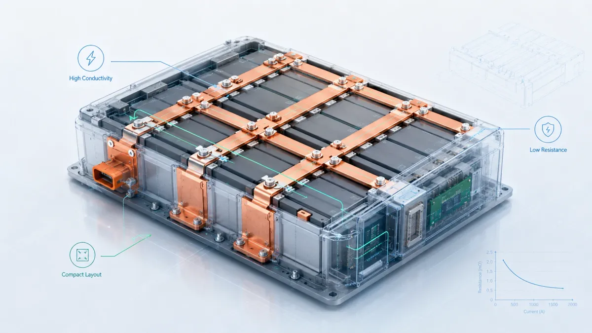
A copper bus bar is a small part compared with a complete vehicle battery pack or a multi-MWh storage container, but it sits directly in the high-current path. When market volumes rise, small engineering weaknesses become large operational problems. A few prototypes can tolerate manual adjustment. Thousands or millions of assemblies cannot. The larger the EV and BESS markets become, the more important it is to standardize the electrical, mechanical, and manufacturing rules for each battery bus bar copper component.
The following table summarizes several industry data points that are useful when discussing copper bus bar requirements with management, customers, and suppliers.
| Industry signal | Data point | Why it matters for battery bus bar copper design | Source |
|---|---|---|---|
| Global EV demand | Electric car sales topped 17 million in 2024 and rose by more than 25% | Higher vehicle volumes require stable bus bar quality, repeatable tolerances, and supplier scalability | IEA Global EV Outlook 2025 |
| EV market share | More than 20% of new cars sold worldwide in 2024 were electric | Battery interconnects are moving from niche components to mainstream automotive supply-chain items | IEA Global EV Outlook 2025 |
| Global battery storage additions | Battery storage additions reached 108 GW in 2025, up around 40% from 2024 | BESS rack, cabinet, PCS, and DC link conductors need scalable high-current copper solutions | IEA battery storage analysis |
| Utility-scale storage | Utility-scale battery storage accounted for around 87 GW of 2025 additions | Large systems increase demand for insulated copper bus bars, plated joints, and standardized cabinet power paths | IEA battery storage analysis |
| 2030 storage requirement | Global energy storage capacity must increase sixfold to 1,500 GW by 2030 in the IEA NZE Scenario; batteries account for 90% of the increase | Energy storage growth requires manufacturable conductors that balance cost, safety, and reliability | IEA Batteries and Secure Energy Transitions |
| Copper conductivity basis | Commercially pure copper products can exceed 100% IACS; temperature and alloying affect conductivity | Material choice, temper, plating, heat rise, and contact design all affect real current performance | Copper Development Association |
These numbers are not included to make the article look technical. They explain a real sourcing problem. Battery manufacturers, storage integrators, and power equipment builders are scaling quickly, but high-current copper components still require careful customization. A drawing may show only length, width, thickness, holes, and bends. Real performance depends on current rating, ambient temperature, allowed temperature rise, surface treatment, insulation, torque, vibration, duty cycle, and how the bus bar is installed.
This is why JUMAI’s engineering conversation usually starts before mass production. A buyer may send a 2D drawing, 3D CAD file, sample, or concept sketch. The best manufacturing review checks more than dimensions. It checks whether a rigid bus bar should actually include a flexible section, whether a laminated conductor needs a larger welded terminal area, whether a braided copper link needs a pressed terminal, whether tin plating should be selective or full-surface, whether insulation windows are large enough for safe bolting, and whether burr direction may damage the coating during assembly. JUMAI’s Battery Busbar Design Guide discusses these issues from the perspective of EV packs and energy storage systems, including rigid, laminated flexible, braided, and hybrid assemblies.
What a battery bus bar actually does inside an EV or BESS system
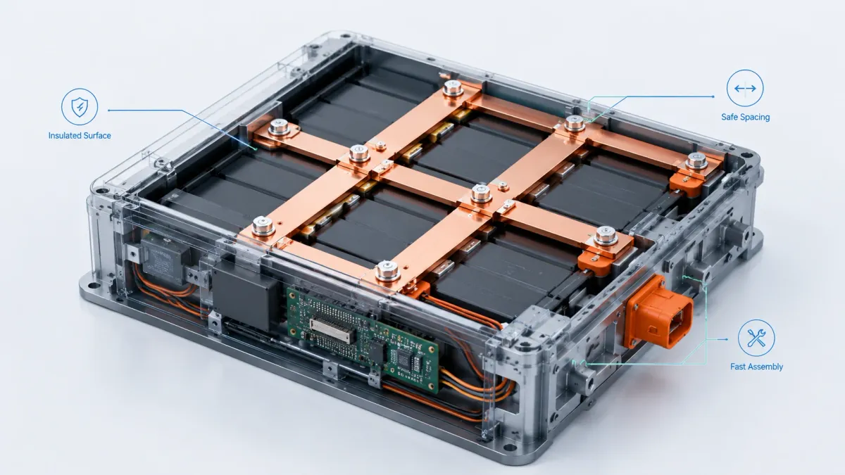
A battery bus bar is a conductor used to connect battery cells, modules, contactors, fuses, relays, shunts, power conversion modules, inverters, chargers, DC link capacitors, or cabinet terminals. In simple language, it carries current from one point to another. In real engineering, it also controls geometry, heat, contact quality, safety spacing, and assembly process.
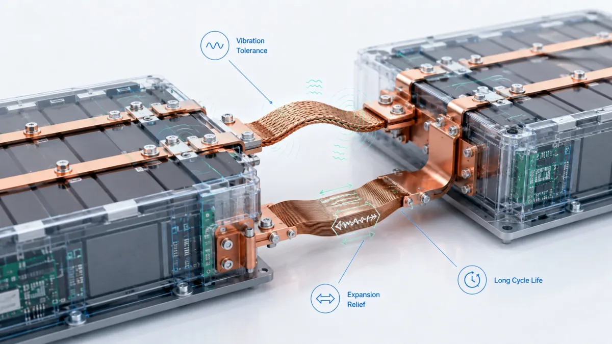
In an EV battery pack, the conductor may connect cell terminals inside a module, connect modules in series or parallel, link a module to a high-voltage junction box, connect the pack output to contactors and fuses, or support sensing and balancing hardware. These parts may operate in a high-vibration environment where the battery case, cooling plate, cell stack, and terminal hardware all move slightly under road shock and thermal expansion. A rigid copper strip can carry current, but it may also transfer mechanical stress into a terminal if the real assembly does not perfectly match the drawing. For this reason, laminated flexible copper busbars and braided copper busbars are widely used where controlled movement is needed.
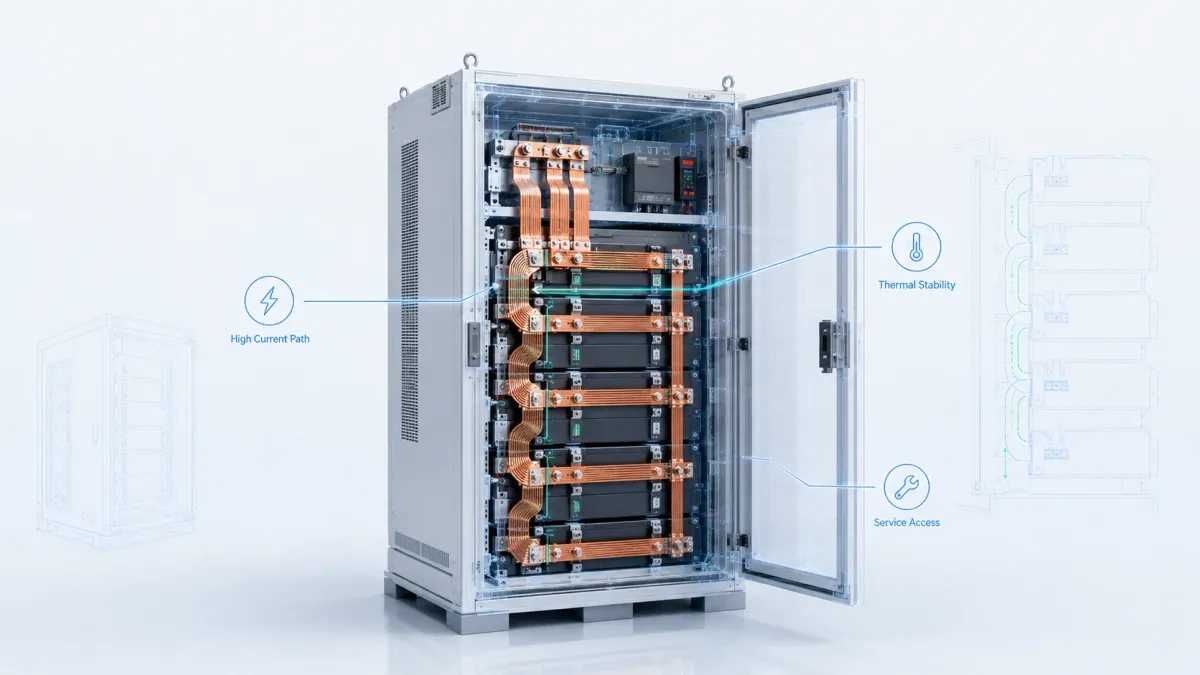
In a BESS cabinet or container, the environment is different but still demanding. The system may include many battery racks, DC bus paths, protection devices, power conversion units, HVAC equipment, and monitoring systems. Here the bus bar may be longer, more exposed to cabinet routing constraints, and more influenced by installation labor. Technicians may need to install the same part many times, sometimes in tight spaces. A well-designed copper bus bar can reduce cable clutter, improve repeatability, shorten assembly time, simplify inspection, and help maintain consistent clearance and creepage distances.
In both EV and BESS applications, battery bus bar copper provides several advantages over large cables. Flat copper has a predictable cross-section and can be punched, bent, plated, and insulated to a controlled shape. It can support compact packaging because it does not require the same bending volume as a large cable. It can reduce voltage drop when sized correctly. It can also provide a clean interface for bolted joints, welded joints, or custom terminals. However, copper bus bars are not automatically better in every location. If a connection must move in multiple directions, a braided copper link may be better. If a conductor must bend inside a compact module while keeping a flat profile, a laminated flexible busbar may be better. If a cabinet has stable fixed terminals, a rigid copper busbar may be the best cost-performance choice.
The correct design begins with application conditions, not with a catalog size. The current may be continuous, peak, pulse, charge-only, discharge-only, or bidirectional. The allowed temperature rise may be conservative for efficiency or higher for compactness. The voltage may require insulation coordination and dielectric testing. The mechanical environment may include vibration, shock, thermal cycling, and installation misalignment. The production volume may favor CNC bending at prototype stage and stamping or custom tooling at volume. The surface may require tin, nickel, silver, bare copper, or selective plating. These are not cosmetic choices. They determine whether a battery bus bar copper solution performs safely for years.
Why copper is still preferred for high-current battery bus bars
Copper remains widely used in high-current battery conductors because it combines high electrical conductivity, high thermal conductivity, good formability, good availability, and mature manufacturing knowledge. The Copper Development Association explains that IACS is a relative measure of conductivity and that commercially pure copper products can have conductivity values greater than 100% IACS because of improved processing. The Copper Development Association also notes in its busbar guidance that, for energy efficiency, busbar systems should generally be designed around a 30°C temperature rise above ambient or less, and that temperature rises above 65°C are not recommended for efficient design.
For battery projects, this matters because heat is not only a safety issue. Heat is also wasted energy. Every milliohm of unnecessary resistance creates I²R loss, and loss increases with the square of current. A conductor that looks acceptable at 100 A may become a major heat source at 500 A or 1,000 A. A contact surface that is slightly oxidized, uneven, contaminated, undertorqued, or poorly plated can become the hottest point in the circuit even when the copper cross-section is large.
C11000 electrolytic tough pitch copper and T2 copper are common choices for bus bar production because they offer high conductivity and broad manufacturability. The Copper Development Association’s alloy data for C11000 copper describes it as high-conductivity copper with a minimum conductivity of 100% IACS in the annealed condition and a copper content minimum of 99.90%. JUMAI’s Custom Copper Busbars page also identifies high-purity T2/C11000 copper as a key material basis for its copper busbar manufacturing.
Copper is not selected only because it conducts electricity well. It also conducts heat well, which helps spread localized heat away from contact zones and high-current paths. It can be punched, bent, stamped, pressed, welded, diffusion bonded, plated, and insulated. It can be made into rigid bars, laminated flexible stacks, braided straps, hybrid conductors, and custom terminals. It can also be combined with deep-drawn or stamped metal components when the assembly requires a special housing, bracket, shield, sensor part, or contact geometry.
Aluminum is sometimes considered for weight or cost reasons, especially in large vehicles or certain cabinet structures. However, aluminum has lower conductivity than copper, requires larger cross-section for the same resistance target, and creates different jointing and surface-treatment challenges. For compact high-current battery paths, copper often remains the practical choice because it allows a smaller conductor for a given resistance target. This is especially valuable in EV modules, high-voltage junction boxes, compact BESS racks, data center power shelves, and converter cabinets.
The final choice should still be engineering-driven. Copper grade, thickness, width, temper, forming method, plating, insulation, and joint design should be selected together. A high-conductivity copper material cannot compensate for a poorly designed contact. A thick copper bar cannot compensate for a bend radius that causes cracking. A good insulation material cannot compensate for a design that lacks adequate creepage and clearance. A battery bus bar copper part should be reviewed as a small electrical subsystem, not as a commodity metal blank.
Choosing between rigid, laminated flexible, braided, and hybrid copper bus bars
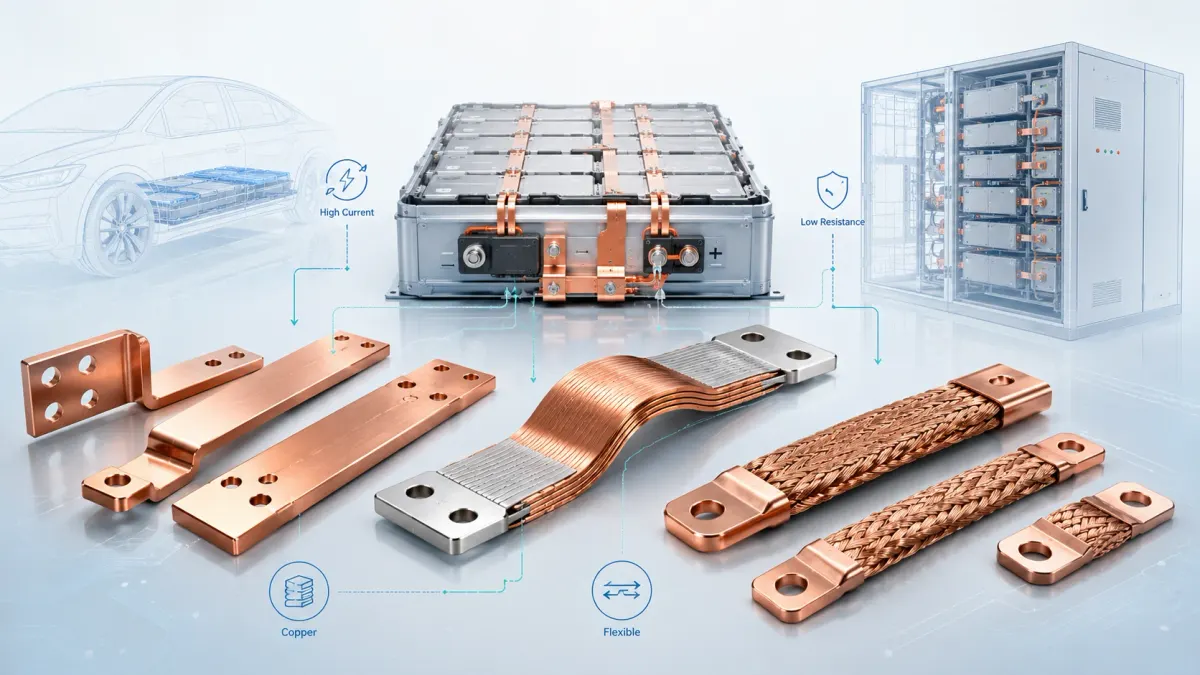
Battery and energy storage systems rarely use only one conductor type. A fixed DC link inside a cabinet may use a rigid copper bar. A module bridge in a pack may use a laminated flexible busbar. A grounding or vibration-sensitive connection may use a braided copper link. A custom high-voltage junction assembly may use a rigid terminal plate connected to a flexible section with selective insulation and plated contact windows.
JUMAI manufactures all three main busbar categories: hard or rigid busbars, soft or braided busbars, and laminated flexible busbars. The company’s Rigid Busbars vs Flexible Busbars and Flexible Copper Busbar articles provide additional background for buyers comparing these structures. The table below gives a practical selection overview.
| Bus bar type | Basic construction | Best fit in battery and storage projects | Main advantages | Key design questions |
|---|---|---|---|---|
| Rigid copper busbar | Solid copper strip or plate, cut, punched, bent, plated, and insulated if needed | Fixed terminals, stable cabinet layouts, switchgear, PCS cabinets, DC distribution, battery rack links | Strong mechanical positioning, predictable geometry, efficient current path, cost-effective at scale | What current, allowed temperature rise, bend radius, hole tolerance, plating, insulation, and short-circuit condition are required? |
| Laminated flexible copper busbar | Multiple thin copper foils or laminations joined at terminal zones while the center span remains flexible | EV module links, compact battery packs, inverter links, BESS modules with thermal expansion or assembly tolerance | Low resistance with controlled flexibility, compact flat routing, reduced terminal stress, good heat spreading | What foil thickness, layer count, welded length, bend radius, insulation material, fatigue requirement, and contact window are needed? |
| Braided copper busbar | Fine copper wires woven into flat or round braid with pressed, welded, soldered, or crimped terminals | Vibration, grounding, thermal expansion, transformer links, pack-to-cabinet movement, misalignment compensation | Excellent multi-axis flexibility, vibration absorption, fatigue tolerance, easy movement compensation | What braid density, wire diameter, terminal type, plating, movement range, current rating, and insulation sleeve are needed? |
| Hybrid copper assembly | Combination of rigid section, flexible section, braid, stamped accessory, insulation, and plated contact areas | Custom EV/BESS assemblies where one conductor must solve several electrical and mechanical problems | Optimized balance between rigidity, flexibility, manufacturability, and assembly speed | Which areas must remain rigid, which must move, how will the part be installed, and how should the interface be tested? |
A common mistake is choosing a rigid conductor only because it is easy to draw. If the battery modules move slightly during thermal cycling, or if the assembly tolerance is not controlled tightly enough, that rigid part may push or pull on terminals. The conductor may pass an initial electrical test but fail later through fatigue, terminal damage, loosening, or increased contact resistance. A laminated flexible copper busbar can absorb small movement while maintaining a compact flat shape. A braided copper busbar can absorb larger or multi-axis movement where a laminated structure may not be ideal.
Another common mistake is choosing a flexible part when a rigid part would be better. Flexibility is valuable only where movement, vibration, misalignment, or installation tolerance must be managed. A rigid busbar may be cheaper, easier to inspect, easier to fixture, and more stable in a fixed cabinet. It may also allow cleaner insulation masking and more repeatable terminal geometry. The best solution is not “flexible everywhere” or “rigid everywhere.” It is a conductor architecture matched to each current path.
JUMAI’s manufacturing role is useful here because it can review the copper conductor from both electrical and production perspectives. For example, a customer may request a laminated flexible busbar with a very short flexible section. From an electrical standpoint, the conductor might carry the current. From a mechanical standpoint, the flexible section may be too short to reduce strain. From a manufacturing standpoint, the weld area may be too close to the bend zone. Early DFM review can prevent this kind of problem before tooling or sample production.
Ampacity, temperature rise, and voltage drop in simple language
Ampacity means the amount of current a conductor can carry continuously without exceeding its temperature limit under specified conditions. For battery bus bar copper parts, ampacity is not a fixed property of the metal alone. It depends on cross-sectional area, surface area, ambient temperature, enclosure ventilation, conductor orientation, surface emissivity, insulation, plating, nearby conductors, duty cycle, joint quality, and acceptable temperature rise.
This is why a simple statement such as “a 30 mm × 3 mm copper bar can carry X amps” is incomplete. The same copper bar behaves differently in open air, inside a sealed battery pack, inside a cabinet with forced air, under heat shrink insulation, under epoxy coating, or next to another hot conductor. It also behaves differently if the current is continuous, intermittent, pulsed, or peak for only a few seconds.
The basic physics is easy to understand. Copper has resistance. Current flowing through resistance creates heat. The heat must leave the conductor through conduction, convection, and radiation. If heat generation is greater than heat dissipation, the bus bar temperature rises. A larger cross-section lowers resistance, but a larger surface area also improves heat dissipation. A flat bar shape is useful because it can provide a large surface area relative to cross-section. However, insulation may reduce direct heat transfer to air, and compact battery packs may have limited airflow.
Voltage drop is another practical issue. In low-voltage, high-current systems, even a small resistance can create meaningful voltage loss and heat. In high-voltage battery systems, current may be lower for the same power level compared with low-voltage systems, but insulation, creepage, clearance, and arc risk become more important. For EV architectures moving toward higher voltage platforms and BESS systems using high DC voltage strings, conductor design must consider both thermal performance and insulation coordination.
JUMAI’s Copper Busbar Ampacity: A Calculation Guide provides a more detailed explanation of how ampacity depends on heat generation and heat dissipation. In an RFQ conversation, the buyer should not ask only for “a copper bar of this size.” A better request provides current rating, peak current, duration, ambient temperature, allowed temperature rise, cooling condition, insulation requirement, conductor orientation, duty cycle, and test expectations. This allows the manufacturer to identify obvious risks and suggest design improvements.
For business decisions, it is useful to remember that higher copper weight is not always wasteful and lower copper weight is not always economical. If a slightly larger cross-section reduces heat, improves efficiency, stabilizes contact temperature, and reduces failure risk, it may reduce total system cost. On the other hand, oversizing every conductor can increase material cost, weight, packaging difficulty, and installation burden. The right design target is optimized performance, not maximum copper and not minimum copper.
Contact resistance: the small interface that can create big heat
Many bus bar problems do not occur in the middle of the copper conductor. They occur at the joint. A bolted connection, welded terminal, pressed braided terminal, or plated contact window can become the weakest point in the current path. A low-resistance conductor can still overheat if contact resistance is high.
Contact resistance is influenced by surface flatness, surface finish, plating, oxidation, contamination, bolt torque, washer selection, contact pressure, hole alignment, thermal cycling, vibration, and relaxation over time. Copper oxide on a contact area can increase resistance. Burrs around holes can prevent full contact or damage insulation. Insulation that creeps into a contact window can reduce effective contact area. A hole pattern that forces the installer to bend the bus bar during assembly can create uneven pressure. A terminal that is too thin may deform under torque. A terminal that is too hard or warped may not seat evenly.
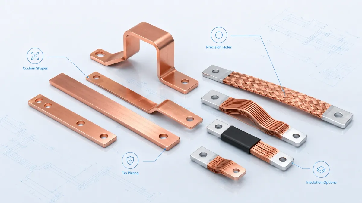
This is where plating becomes important. Tin plating is commonly used to reduce oxidation and support stable contact performance in many electrical environments. Nickel plating may be considered for higher-temperature or harsher environments. Silver plating may be used where very low contact resistance or special high-performance contact behavior is required, although cost is higher. Bare copper may be acceptable in some applications, but the contact environment and maintenance expectations must be considered.
Selective plating is often a good solution for battery bus bar copper parts. The whole conductor may not need plating if only the terminal pads are used for electrical contact. Selective tin, nickel, or silver plating can protect the important interface while controlling cost. However, plating masks must be designed clearly. The drawing should define which areas are plated, which areas are insulated, which areas remain bare, and which dimensions are critical after plating and coating.
For laminated flexible busbars, the welded or bonded terminal area is especially important. The copper foils must act like a solid conductor at the terminal while the middle span remains flexible. If the welded area is too small, current sharing may be uneven. If welding heat is not controlled, flatness and material condition may be affected. If the weld is too close to the bend zone, fatigue risk may increase. For braided copper busbars, terminal compression or welding must create a stable low-resistance connection between many fine wires and the terminal pad.
A good supplier should therefore review contact design as carefully as conductor size. JUMAI’s Battery Busbar Design Guide emphasizes that the joint is often the weakest point and that contact resistance depends on surface material, flatness, pressure, contamination, plating, oxide layer, torque, washer choice, and long-term relaxation. For buyers, this means the RFQ should include contact method, mating material, bolt size, torque target, plating preference, washer style if known, and inspection requirement.
Insulation, clearance, creepage, and safety requirements
Battery bus bars often operate near other conductors, grounded metal, cell cans, cooling plates, brackets, sensors, covers, or service tools. Insulation is therefore not simply a colored protective layer. It is part of the electrical safety design.
The key concepts are straightforward. Clearance is the shortest distance through air between conductive parts. Creepage is the shortest distance along an insulating surface between conductive parts. Solid insulation is the insulating material between conductive parts. These distances and materials depend on voltage, pollution degree, overvoltage category, material group, altitude, environment, and product standard. For electric road vehicles, ISO 6469-3:2021 specifies electrical safety requirements for voltage class B electric circuits of electric propulsion systems and connected auxiliary systems, including protection against electric shock and thermal incidents. For insulation coordination in low-voltage equipment, IEC 60664-1:2020+A1:2025 provides requirements for clearances, creepage distances, and solid insulation for equipment up to AC 1,000 V or DC 1,500 V connected to low-voltage supply systems.
For stationary energy storage, UL 1973 is a relevant safety standard for batteries used in stationary applications such as PV, wind turbine storage, UPS, rail, and vehicle auxiliary power applications. A copper bus bar supplier normally does not certify the complete battery system, but the bus bar design must support the customer’s system-level safety strategy. This means the copper part should be designed with the correct insulation material, coating thickness, exposed terminal window, dielectric test requirement, traceability, and documentation.
Common insulation options include heat shrink tubing, PVC dipping, epoxy powder coating, PA or PET film, sleeves, custom molded covers, and selective insulation masks. Each has advantages and limitations. Heat shrink is flexible and useful for many simple shapes, but it may not cover complex geometry as evenly as coating. Epoxy powder coating can provide a durable controlled surface on rigid bars, but masking and edge coverage must be managed carefully. Film insulation can be useful for laminated flexible busbars, especially when a thin, controlled, flexible insulation system is needed. Sleeves may be used on braided conductors where movement must remain possible.
JUMAI’s Insulated Bus Bars for Battery Packs, Switchgear and Power Cabinets article explains that insulation selection should consider project condition, movement, voltage, abrasion, contact windows, and production method. For example, a fixed low-vibration cabinet may use a rigid insulated copper busbar. A battery module with thermal expansion may need a laminated flexible insulated busbar. A grounding or transformer link with multi-axis movement may need a braided insulated copper busbar.
One practical rule is to design insulation early. If insulation is added after copper geometry is finalized, many problems can appear: holes become too small, contact windows are misaligned, coating is damaged during installation, bends are too tight for the material, creepage paths are not sufficient, or the part no longer fits into the available space. The drawing should show insulation boundaries, bare copper windows, plating areas, coating thickness, color if needed, dielectric test requirement, and acceptable cosmetic standards.
Manufacturing process: from drawing to stable production
A battery bus bar copper project often moves through several stages: concept, prototype, validation, pilot production, and mass production. The best manufacturing approach may change at each stage. Early samples may be produced by laser cutting, punching, CNC bending, manual fitting, or simple insulation. Once the design is validated, high-volume production may require custom fixtures, stamping tools, progressive dies, automated inspection, selective plating masks, controlled coating processes, and standardized packaging.
The core manufacturing steps for rigid copper busbars include material selection, cutting, punching, deburring, bending, surface preparation, plating, insulation, inspection, and packaging. For laminated flexible busbars, the process may include copper foil preparation, stacking, terminal area welding or diffusion bonding, shaping, insulation, terminal finishing, and testing. For braided copper busbars, the process may include wire selection, braiding, cutting, terminal forming, pressing or welding, plating, insulation, and inspection.
Deburring deserves special attention. Burrs can damage insulation, prevent proper contact, create assembly scratches, or become contamination inside a battery pack. Hole quality is equally important because bus bars are often bolted to sensitive terminals. Hole diameter, slot design, countersink requirements, edge distance, burr direction, and flatness around the contact area should be controlled. Bend quality matters because copper work-hardens and can crack if bend radius, temper, and thickness are not matched correctly.
For flexible busbars, terminal quality is critical. In a laminated flexible copper busbar, the terminal area must be sufficiently bonded so current flows evenly across layers. The flexible span should not be accidentally stiffened by too much welding or coating. In a braided copper busbar, the terminal must capture many fine wires without creating loose strands, high resistance, or fatigue points. For high-current battery systems, these details can determine whether the part remains stable under vibration and thermal cycling.
JUMAI’s advantage is that it is not limited to one simple copper shape. Its service range includes soft copper busbars, rigid copper busbars, braided copper busbars, laminated flexible busbars, plating, insulation, and related precision processing. The company also provides deep-drawn components, stamping die customization, and tooling or mold components. This matters when a battery project needs more than a single flat conductor. A complete assembly may need a copper busbar, stamped sensor tabs, deep-drawn copper or aluminum parts, brackets, covers, positioning features, and custom tooling. Reviewing these parts together can reduce assembly conflicts.
For buyers, the practical recommendation is to involve the manufacturer before the design is frozen. It is much cheaper to adjust a bend radius, hole slot, contact window, or insulation mask during design review than after validation. It is also useful to share the system context. A supplier does not need confidential pack architecture to provide useful feedback, but it does need enough information about current, voltage, movement, temperature, installation method, and testing requirement to identify risks.
Practical specification checklist for RFQ and design review
A clear RFQ reduces quoting errors, avoids assumptions, and helps the supplier return useful engineering feedback. Many purchasing delays happen because the drawing defines shape but not performance. For a battery bus bar copper solution, performance details are just as important as dimensions.
The table below can be used as a practical checklist before sending drawings to JUMAI or another custom bus bar manufacturer.
| Specification field | Example information to provide | Why it matters |
|---|---|---|
| Application | EV module interconnect, BESS rack busbar, HV junction box, DC link, UPS cabinet, charging system | Helps supplier understand vibration, safety, and production context |
| Current rating | 300 A continuous, 600 A peak for 10 seconds, pulse profile if available | Determines conductor cross-section, heat rise, terminal design, and test needs |
| Voltage level | 400 V DC, 800 V DC, 1,000 V DC, 1,500 V DC maximum | Affects insulation, clearance, creepage, dielectric test, and exposed copper design |
| Bus bar type | Rigid, laminated flexible, braided, or hybrid | Defines process route, tooling, flexibility, and cost structure |
| Copper material | C11000, T2 copper, C10200, customer-specified grade | Affects conductivity, forming, welding, sourcing, and cost |
| Dimensions and tolerances | Thickness, width, length, hole diameter, slot geometry, bend angles, flatness | Controls fit, assembly speed, and contact pressure |
| Surface finish | Bare copper, tin plating, nickel plating, silver plating, selective plating | Affects oxidation resistance, contact stability, temperature capability, and cost |
| Insulation | Heat shrink, epoxy powder, PVC dipping, PA/PET film, sleeve, custom cover | Affects voltage safety, abrasion, bend behavior, inspection, and assembly |
| Contact method | Bolted, welded, pressed, riveted, terminal block, mating material, torque if known | Contact design often controls heat and long-term reliability |
| Mechanical environment | Vibration, shock, thermal cycling, movement range, installation misalignment | Helps choose rigid, flexible, braided, or hybrid construction |
| Thermal environment | Ambient temperature, enclosure type, airflow, nearby heat sources, cooling plate contact | Ampacity depends strongly on heat dissipation conditions |
| Testing requirement | Dimensional inspection, conductivity, resistance, dielectric withstand, pull test, plating thickness | Ensures quotation includes correct QC scope |
| Production volume | Prototype, pilot batch, annual quantity, target ramp-up | Determines whether CNC, stamping, custom tooling, or process automation is most economical |
| Documentation | Material certificate, plating report, inspection report, PPAP-style documents if required | Supports OEM approval, traceability, and quality management |
This checklist is intentionally practical. It helps both sides avoid vague terms such as “high current,” “good insulation,” or “standard copper.” For example, “high current” may mean 150 A in a small module, 800 A in a cabinet, or several thousand amps in a power distribution unit. “Good insulation” may mean simple touch protection in one project and a defined dielectric withstand test in another. “Standard copper” may mean C11000 in one supply chain and T2 copper in another.
A clear RFQ also helps identify value engineering opportunities. If a prototype uses a very thick rigid copper bar only because the engineer wanted safety margin, JUMAI may suggest a wider but thinner geometry, a laminated structure, selective plating, or a different bend design. If the drawing shows a braided copper link but the installation requires a controlled flat package, a laminated flexible busbar may be more suitable. If the insulation is expensive because the whole part is coated, selective insulation or a custom cover may be considered.
Design mistakes that increase cost or risk
The first mistake is sizing the bus bar only by cross-sectional area. Cross-section is important, but ampacity also depends on heat dissipation, enclosure conditions, insulation, surface area, conductor orientation, and contact resistance. A narrow thick bar and a wide thin bar with the same area may not behave the same thermally. A coated bar and a bare bar may not behave the same. A bus bar inside a sealed pack and one in open air are not equivalent.
The second mistake is ignoring the joint. If a bolted contact has poor flatness, insufficient pressure, oxidation, contamination, or a small contact area, heat can concentrate at the joint. This is especially dangerous because the conductor body may look normal while the contact point becomes hot. The drawing should define contact windows, plating, flatness, hole quality, and installation requirements.
The third mistake is choosing rigid copper where movement exists. EV packs experience vibration, shock, and thermal cycling. BESS racks also experience temperature variation and installation tolerance. A rigid conductor can transfer stress to terminals if it cannot absorb movement. Laminated flexible copper busbars and braided copper links can reduce this risk when used correctly.
The fourth mistake is choosing a flexible busbar without defining fatigue and movement. Flexibility must be engineered. A flexible section that is too short may not reduce stress. A bend radius that is too tight may damage foils or insulation. A braid terminal that is poorly pressed may loosen or heat. The supplier needs movement range, installation direction, expected vibration, and service life expectations.
The fifth mistake is adding insulation late. Insulation affects part size, bend behavior, creepage, clearance, contact windows, coating thickness, and inspection. Late insulation changes often create conflicts with holes, terminals, covers, and assembly tools. The correct approach is to design copper geometry and insulation together.
The sixth mistake is treating plating as cosmetic. Plating is often a functional contact decision. Tin, nickel, and silver have different cost, contact, temperature, and corrosion implications. Selective plating can reduce cost, but the plated areas must align with real contact surfaces. Poor plating definition can lead to quotation confusion and quality disputes.
The seventh mistake is overcomplicating the prototype in a way that cannot scale. A handmade prototype may pass a lab test, but mass production needs repeatable tooling, fixtures, inspection, and process control. If annual volume is high, the design should be reviewed for stamping feasibility, bending repeatability, deburring, coating masks, and packaging.
The eighth mistake is not sharing enough information with the supplier. Some buyers send only a PDF drawing and ask for the lowest price. This may be enough for a simple copper strip, but not for a high-current battery bus bar copper assembly. A better supplier conversation includes current, voltage, temperature, movement, insulation, plating, quantity, testing, and assembly context.
How JUMAI supports custom battery bus bar copper projects
JUMAI supports customers who need custom copper busbars for EV battery systems, renewable energy equipment, BESS cabinets, power distribution hardware, data centers, industrial power systems, and related high-current assemblies. The company’s Custom Copper Busbars service page describes rigid busbars, soft or braided busbars, and laminated flexible busbars, along with plating, insulation, CNC bending, punching, cold pressing, and diffusion welding capabilities.
For rigid copper busbars, JUMAI can manufacture solid copper conductors with custom cutting, punching, slotting, bending, plating, and insulation. These are suitable for fixed current paths in cabinets, high-voltage distribution boxes, switchgear, power conversion units, charging hardware, and battery racks where geometry is stable.
For laminated flexible busbars, JUMAI can produce multi-layer copper foil conductors designed to bend, absorb thermal expansion, and route current in tight spaces. These are useful in EV battery modules, BESS modules, inverters, compact power electronics, and any location where a flat conductor must combine high current capacity with controlled flexibility.
For braided copper busbars, JUMAI can provide woven copper conductors with custom pressed terminals, plating, and insulation. These are useful when vibration, misalignment, repeated movement, or grounding flexibility is more important than a fixed flat profile.
For hybrid assemblies, JUMAI can help combine rigid and flexible features. A part may use a rigid contact area, a flexible middle section, selective tin plating, an insulation sleeve, and stamped positioning features. This is often the most practical solution when the conductor must fit a complex battery or cabinet layout.
JUMAI also provides deep drawing, stamping die customization, and tooling or mold components. Although copper busbars are the main focus for many electrical customers, these additional capabilities can be valuable when the power path is part of a larger mechanical assembly. For example, a battery system may require a copper conductor plus a stamped bracket, deep-drawn protective cover, custom terminal shield, or sensor mounting feature. Coordinating these components with one manufacturing partner can reduce fit problems and shorten development cycles.
Buyer-focused example: from concept to production-ready bus bar
Consider a BESS cabinet manufacturer designing a 1,500 V DC energy storage rack. The cabinet needs to connect several battery modules to a fuse, contactor, shunt, and DC output terminal. The original concept uses several large cables because cables are familiar and flexible. However, the cabinet is crowded, cable routing is inconsistent, and assembly workers need extra time to bend and secure each cable.
A custom copper bus bar solution may improve the design. Fixed cabinet paths can be replaced with rigid insulated copper busbars. Areas with small installation tolerance can use slotted holes or a short laminated flexible section. Contact areas can use selective tin plating. Insulation can be designed with exposed terminal windows so the technician does not need to trim material during assembly. The final busbar can be inspected before installation, reducing variation on the assembly line.
Now consider an EV battery module. The module terminals experience small movement because cells expand and contract during charge and discharge, and the vehicle experiences road vibration. A thick rigid copper strip could carry the current, but it may stress the terminals. A laminated flexible copper busbar may be better because the terminal zones can be welded into stable contact pads while the center span remains flexible. The insulation can be designed to cover the flexible span while leaving clean plated terminal windows. The result is a compact battery bus bar copper part that supports current flow, movement absorption, and assembly consistency.
In both examples, the best result comes from early design review. The buyer provides current rating, voltage, maximum temperature, installation space, movement condition, preferred plating, insulation requirement, annual quantity, and drawings. JUMAI reviews manufacturability, identifies risk points, suggests adjustments, and produces prototypes for fit and function testing. After validation, the process can move toward production tooling, inspection planning, and packaging.
Quality control and documentation expectations
Quality control for battery bus bars should match the risk level of the application. A simple low-current grounding strap does not require the same inspection scope as a high-voltage battery module interconnect. However, high-current EV and BESS projects usually need more than basic visual inspection.
Dimensional inspection is the starting point. Hole location, hole diameter, slot size, bend angle, flatness, thickness, width, terminal geometry, and overall profile should be checked according to the drawing. For assembled or flexible busbars, terminal zone dimensions and flexible section length should be controlled. For insulated parts, coating thickness, insulation boundaries, exposed copper windows, and surface defects should be checked.
Electrical inspection may include resistance measurement, conductivity verification, or continuity checks depending on the product. For high-current parts, the measurement method must be suitable because small resistance values can be difficult to measure accurately. Contact resistance testing may be needed for critical assemblies.
Surface inspection may include plating thickness, adhesion, discoloration, oxidation, scratches, and mask quality. Tin plating, nickel plating, and silver plating should be inspected according to the agreed requirement. If selective plating is used, the boundary between plated and unplated areas should be controlled.
Insulation testing may include visual inspection, coating thickness measurement, adhesion checks, dielectric withstand testing, or flame-retardant material confirmation depending on the application. JUMAI’s copper busbar service page notes insulation options such as heat shrink tubing, PVC dipping, and epoxy powder coating, and mentions UL94 V-0 flame-retardant formulation capability. The buyer should define whether a material certificate, dielectric test report, or special inspection record is required.
Traceability may be important for OEM, automotive, energy storage, and industrial customers. Material certificates, plating reports, inspection records, batch numbers, and packaging labels can help support quality management. If the project requires PPAP-style documentation or customer-specific approval documents, this should be discussed early because it affects cost and lead time.
Cost factors: what really drives the price of a copper bus bar
The price of a battery bus bar copper component is influenced by copper weight, material grade, process complexity, tolerance, plating, insulation, inspection, tooling, packaging, and volume. Copper weight is important, but it is not the only cost driver.
A simple flat copper bar with two holes may be inexpensive. A three-dimensional rigid busbar with tight tolerances, multiple bends, tin-plated terminal pads, epoxy coating, masked contact windows, laser marking, and dielectric testing will cost more. A laminated flexible copper busbar may require multiple copper foils, stacking, welding or bonding, forming, insulation, and special terminal inspection. A braided busbar may require wire braiding, terminal pressing, plating, and movement-friendly insulation.
Tolerance can significantly affect cost. Very tight hole-position tolerances may require better fixtures, additional inspection, or process changes. Tight flatness requirements may require stress control or secondary operations. Complex bend geometry may require custom tooling. Coating and plating masks may require additional labor or fixtures. If the drawing uses unnecessary precision, the buyer may pay for accuracy that does not improve performance.
Volume also changes the cost structure. For prototypes, CNC cutting and manual processes may be economical because they avoid tooling cost and allow quick changes. For mass production, stamping tools, bending fixtures, plating racks, automated inspection, and custom packaging may reduce unit cost and improve consistency. A good supplier can explain when tooling makes sense.
Design-for-manufacturing review can reduce cost without reducing performance. A slot may solve tolerance stack-up better than forcing a busbar into position. A selective plated pad may reduce cost compared with full plating. A slightly larger bend radius may reduce cracking risk. A standard copper thickness may reduce material lead time. A simplified insulation boundary may reduce masking labor. A modular busbar design may reduce tooling complexity.
For sourcing teams, the practical approach is to compare total value, not only piece price. The lowest quoted copper part may become expensive if it requires rework, causes assembly delays, fails insulation testing, has unstable contact resistance, or cannot scale. A well-designed battery bus bar copper solution should reduce risk across the full project lifecycle.
Sustainability and efficiency considerations
Copper busbars contribute to sustainability in two main ways: electrical efficiency and service life. Lower resistance reduces energy loss during operation. Stable contact design reduces heat, maintenance, and replacement. A busbar that lasts through the intended service life of a battery pack or storage cabinet avoids material waste and downtime.
The efficiency benefit is especially important in high-current systems. Because resistive loss increases with the square of current, small resistance improvements can matter when current is high. Good conductor sizing, proper contact design, suitable plating, and stable insulation all support lower heat and more reliable operation. The Copper Development Association’s busbar guidance emphasizes temperature rise as an energy-efficiency consideration, which aligns with the practical goal of designing busbar systems around reasonable heat rise rather than simply accepting high temperatures.
Sustainability also includes manufacturability. A design that is easy to produce consistently creates less scrap. A busbar that fits correctly without manual force reduces rework. A clear insulation mask reduces rejected parts. A stable plating process reduces quality variation. Good packaging prevents shipping damage. These details may not appear in a high-level environmental statement, but they matter in real production.
Finally, copper is recyclable, and copper recycling is an established industrial practice. However, recyclability does not replace good design. The best sustainability outcome is a copper busbar that uses appropriate material, operates efficiently, avoids premature failure, and can be responsibly handled at end of life.
When to involve JUMAI in your project
The best time to involve a copper busbar manufacturer is before the design is locked. Early review is especially valuable if the project has high current, high voltage, tight space, complex bends, vibration, thermal cycling, selective plating, insulation, or high-volume production requirements.
You should involve JUMAI early if your team is asking any of the following questions:
- Should this battery conductor be rigid, laminated flexible, braided, or hybrid?
- Is the copper cross-section enough for the continuous and peak current?
- Will the allowed temperature rise be realistic inside the actual enclosure?
- Should the contact pads be tin plated, nickel plated, silver plated, or bare copper?
- How large should the bare terminal window be after insulation?
- Can the bend radius be manufactured without cracking or distortion?
- Will the flexible section actually absorb movement?
- Can the same design be produced economically at volume?
- What inspection and documentation should be specified?
For a quotation, send 2D drawings, 3D CAD files, samples if available, current and voltage requirements, insulation and plating preferences, application details, annual quantity, and testing expectations. If some information is unknown, JUMAI can still review the design and identify missing details. This is often better than waiting until every requirement is frozen, because early feedback may prevent expensive redesign.
Design the copper bus bar as part of the system
Battery bus bar copper solutions are becoming more important because EVs, BESS projects, renewable energy systems, charging equipment, data centers, and high-current cabinets are growing in volume and power density. A copper bus bar is not just a conductive strip. It is a current path, a thermal component, a mechanical interface, an insulation carrier, and a production-quality item.
The best busbar design balances electrical performance, thermal behavior, contact reliability, mechanical movement, insulation safety, surface finish, manufacturability, inspection, and cost. Rigid copper busbars are excellent for stable fixed paths. Laminated flexible copper busbars are valuable where compact routing and movement absorption are needed. Braided copper busbars are useful for vibration, grounding, and multi-axis movement. Hybrid assemblies can combine these features when the application requires more than one behavior.
JUMAI supports custom battery bus bar copper projects with rigid, flexible, braided, plated, insulated, and precision-processed copper solutions. For customers designing EV battery packs, BESS racks, high-voltage cabinets, inverters, UPS systems, chargers, and industrial power assemblies, early engineering communication can reduce risk and improve total project value.
If your project requires a custom copper bus bar, prepare your drawings, current and voltage data, insulation needs, plating requirements, movement conditions, and production volume. JUMAI can review the design, suggest manufacturable improvements, and help turn a high-current concept into a reliable production component.
Frequently asked questions about battery bus bar copper
What is the difference between a battery bus bar and a normal copper bar?
A normal copper bar is only a material form. A battery bus bar is an engineered conductor designed for a specific electrical, mechanical, thermal, and assembly environment. It may require controlled current capacity, plating, insulation, hole tolerances, bend geometry, contact windows, dielectric testing, and traceability.
Is copper always better than aluminum for battery bus bars?
Not always, but copper is often preferred in compact high-current applications because it has higher electrical conductivity than aluminum and can provide a lower-resistance path in a smaller cross-section. Aluminum may be considered for weight or cost reasons, but it requires different sizing, jointing, and surface-treatment review.
How do I choose the right copper bus bar thickness?
Thickness depends on continuous current, peak current, allowed temperature rise, ambient temperature, ventilation, insulation, width, conductor orientation, duty cycle, and contact design. There is no universal thickness. Provide current and thermal conditions so the design can be reviewed correctly.
Should a battery bus bar be tin plated?
Tin plating is commonly used to reduce oxidation and improve contact stability, especially at bolted terminal areas. However, nickel, silver, bare copper, or selective plating may be better depending on temperature, corrosion exposure, contact method, cost, and customer standards.
When should I use a laminated flexible copper busbar?
Use a laminated flexible copper busbar when the conductor must carry high current while absorbing small movement, thermal expansion, installation tolerance, or vibration. It is common in EV modules, compact battery packs, BESS modules, and power electronics where a flat flexible current path is useful.
When should I use a braided copper busbar?
Use a braided copper busbar when the connection must handle multi-axis movement, vibration, grounding flexibility, thermal expansion, or misalignment. Braided conductors are made from many fine copper wires and can provide excellent flexibility and fatigue tolerance when properly terminated.
What should I send to JUMAI for a quote?
Send 2D drawings, 3D CAD files, copper grade, current rating, voltage level, surface finish, insulation requirement, contact method, application industry, quantity, and testing requirements. If your design is still early, send the concept and expected conditions so JUMAI can review manufacturability and identify missing specifications.