A flexible busbar is no longer a special component used only when a rigid copper bar cannot fit. In modern battery packs, battery energy storage systems, data center power cabinets, renewable energy converters, EV chargers and industrial drives, it has become a practical way to carry high current while giving the mechanical design room to move. The reason is simple: high-current equipment is becoming smaller, hotter, more modular and more vibration-sensitive. A conductor that only looks good on a drawing may fail in production if it cannot absorb tolerance stack-up, thermal expansion, maintenance movement or road vibration.
For buyers, engineers and sourcing teams, this creates a new challenge. The question is not simply, “How many amps can this copper part carry?” The better question is, “Can this conductor carry the required current, remain cool enough, maintain insulation distance, survive vibration, simplify assembly and remain repeatable in mass production?” That is exactly where a custom flexible busbar can create value.
JUMAI manufactures custom copper busbars for global customers, including hard/rigid copper busbars, soft/braided copper busbars and laminated flexible copper busbars. The company’s Custom Copper Busbars service describes high-purity T2/C11000 copper, custom punching, bending, plating, insulation and engineering review support. Related JUMAI articles such as Flexible Copper Busbar: A Practical Guide for EV Batteries, BESS and Power Distribution, Flexible Busbar vs. Cable: A Comparison and Flexible Copper Busbar Basics for Vibration-Prone Systems provide useful background. This article goes deeper into design logic for battery packs, BESS and high-vibration power systems, with a focus on specifications that help a project move from concept to manufacturable copper parts.
- Why flexible busbar design matters now
- What a flexible busbar really is
- Flexible busbar vs rigid busbar vs cable
- Start with the electrical load, but do not stop there
- Thermal design for battery packs and BESS
- Voltage, insulation, creepage and clearance
- Vibration and movement are design loads
- Battery pack design: from cell module to high-voltage junction box
- BESS design: rack repeatability, safety documentation and field service
- High-vibration power systems beyond EVs
- Selecting the right flexible busbar construction
- Material grade, copper temper and layer design
- Plating and surface finish
- Insulation choices for flexible busbars
- Design for manufacturability: the difference between CAD and production
- Quality control and validation plan
- RFQ checklist for a custom flexible busbar
- Cost drivers and how to control them
- Common design mistakes
- How JUMAI supports flexible busbar projects
- Practical specification example
- Frequently asked questions
- Make the conductor part of the system design
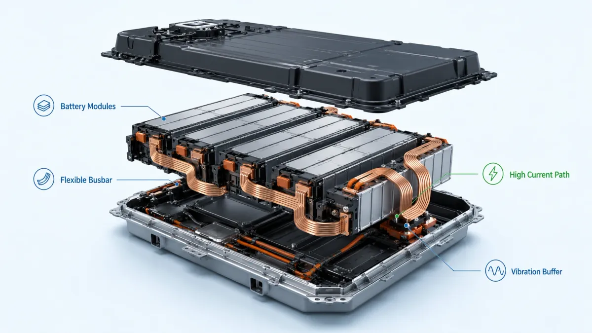
Why flexible busbar design matters now
The demand side is changing quickly. The International Energy Agency reported that global electric car sales grew by 20% in 2025 and exceeded 20 million units, equal to about 25% of new car sales worldwide in that year (IEA Global EV Outlook 2026). Battery storage is also scaling fast: according to the IEA, 108 GW of new battery storage capacity was deployed worldwide in 2025, 40% more than in 2024, and installed capacity was eleven times higher than in 2021 (IEA Global Energy Review 2026). Data centers are another important driver. IEA analysis estimates that data center electricity consumption reached about 415 TWh in 2024, or around 1.5% of global electricity consumption, and could double to about 945 TWh by 2030 in its base case (IEA Energy and AI).
These numbers are not included only as market background. They explain why busbar design is becoming a purchasing and reliability issue. More EVs mean more battery packs, more pack-level service connections, more high-voltage junction boxes and more power electronics. More BESS deployment means more rack interconnects, DC collection paths, power conversion system interfaces and field-serviceable cabinets. More data center load means more high-current power distribution inside switchgear, UPS systems, rack-level power shelves and energy storage backup systems.
When production volume rises, small assembly issues become expensive. A cable that takes two minutes too long to route becomes a labor cost. A lug that can be rotated by the operator becomes a quality variable. A rigid bar that forces a terminal into position may create hidden mechanical stress. A flexible busbar helps by combining a defined copper current path with controlled compliance. It is not a loose cable and it is not a completely rigid beam. It is a conductor designed to carry current and absorb movement at the same time.
| Market or system trend | Practical impact on copper interconnects | Why a flexible busbar becomes attractive |
|---|---|---|
| EV battery pack growth | High current, limited package space, pack vibration, repeated thermal cycling | Flat laminated or braided conductors reduce routing volume and protect terminals from stress |
| BESS deployment growth | Modular racks, DC combiner cabinets, field maintenance, UL/IEC safety requirements | Pre-formed busbars make assembly repeatable and help organize high-current DC paths |
| Higher data center power density | More current inside UPS, switchgear, rack power and backup energy systems | Low-profile copper paths reduce clutter and support predictable thermal behavior |
| Renewable energy and EV charging | High DC current, frequent thermal cycles, outdoor or semi-outdoor cabinets | Plated and insulated flexible busbars improve corrosion resistance and installation repeatability |
| Global sourcing pressure | OEMs need drawings, prototypes, PPAP-like quality evidence and stable lead time | Custom busbar manufacturing reduces redesign risk when electrical, mechanical and process teams work together |
What a flexible busbar really is
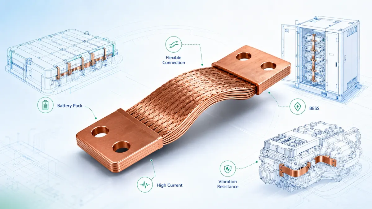
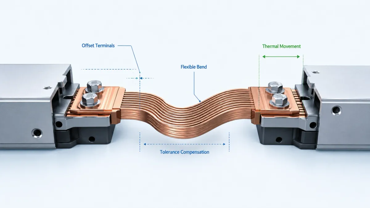
A flexible busbar is an electrical conductor made to carry significant current while allowing controlled bending, twisting or movement. The word “flexible” does not mean weak. It means that the conductor has a designed flexible region and a defined terminal region. The terminal region must be stable enough to bolt, weld, rivet or clamp. The flexible region must be compliant enough to absorb movement without concentrating stress at the electrical joint.
The most common constructions are laminated copper foil busbars, braided copper busbars and soft copper links. A laminated flexible busbar is usually made from multiple thin copper layers stacked together. The ends can be diffusion bonded, press welded, resistance welded or otherwise consolidated to create solid terminal pads. The center area remains flexible because the individual copper layers can slide slightly relative to one another as the part bends. JUMAI’s Diffusion Bonded Flexible Busbar Guide explains this construction from a manufacturing perspective.
A braided copper busbar is made from many fine copper wires woven into a flat or tubular braid, usually with solid terminals at the ends. It is highly useful where multi-axis motion, vibration, grounding, cabinet-door movement or alignment compensation are more important than a very flat laminated geometry. JUMAI’s article What Is a Braided Busbar Used For? discusses cabinet, plating-line, grounding and EV-related applications.
A soft copper link may look similar to a short flat strip, but it is made from annealed copper or a geometry that allows easier bending than a rigid busbar. It may be selected for simple offsets, moderate vibration or cost-sensitive designs where a laminated stack is not necessary.
The key idea is that a flexible busbar is an engineered interconnect. Its value depends on geometry, copper grade, number of layers, width, thickness, terminal design, hole pattern, bend allowance, plating, insulation and quality control. A low-cost strip of copper with two holes may carry current, but it may not solve the mechanical, thermal or assembly problem.
Flexible busbar vs rigid busbar vs cable
Rigid busbars are excellent when geometry is stable, current is high and the conductor can also serve as a structural element. They are common in switchgear, power cabinets, transformers and distribution panels. JUMAI produces rigid busbars through precision cutting, punching, CNC bending, plating and insulation for applications where strength and fixed positioning matter.
Cables are excellent when routing must be very free or when a product needs widely available off-the-shelf conductors. However, high-current cables often require large bend radii, lugs, crimping, clamps and strain relief. In a compact battery pack or power conversion cabinet, cable routing can consume more space than expected. It can also introduce process variability: cable length, lug orientation, crimp quality and tie-down position must all be controlled.
A flexible busbar sits between these options. Compared with a cable, it provides a flatter, more predictable current path. Compared with a rigid busbar, it reduces stress transfer between components. Compared with both, it can be customized to the assembly sequence. The conductor can be formed to avoid a fuse, pass over a shunt, connect a contactor to a DC link capacitor, or bridge a battery module interface with controlled movement.
The commercial value is often found in the factory, not only in the electrical calculation. If a flexible busbar removes two cable clamps, one crimping operation, one operator orientation decision and one rework risk, it can reduce total installed cost even if the component price is higher than a simple cable. In battery and BESS projects, a conductor that shortens assembly time and improves repeatability can be worth more than a low piece price.
Start with the electrical load, but do not stop there
The first design input is current. The project team should define continuous current, peak current, pulse duration, duty cycle, fault current exposure and acceptable voltage drop. For DC battery systems, continuous current and transient current may be very different. A BESS rack may operate for long periods at moderate current and occasionally at higher charge or discharge current. An EV pack may experience acceleration peaks, regenerative braking peaks and fast-charging conditions. A UPS or data center backup module may need high short-duration discharge current during transfer events.
The basic copper loss is simple:
Power loss = I²R
This formula is easy to understand but easy to underestimate. If current doubles, heat generation increases by four times at the same resistance. Therefore, small resistance differences in the terminal, plating interface, welded area or bolted joint matter. A flexible busbar should be designed not only for cross-sectional copper area but also for joint quality and heat removal.
Copper is selected because it combines high electrical conductivity and high thermal conductivity. The Copper Development Association lists C11000 as high-conductivity copper with 99.90% minimum copper and a minimum conductivity of 100% IACS in the annealed condition (CDA C11000 Alloy). CDA copper data also gives typical electrical-grade copper values such as 100.0-101.5% IACS conductivity at 20°C, annealed resistivity around 1.7241-1.70 micro-ohm-cm, and thermal conductivity around 397 W/m-K at 20°C (CDA copper fact sheet). These properties explain why T2/C11000 copper is widely used for busbars.
| Design data point | Practical value for flexible busbar design | Design note |
|---|---|---|
| C11000 copper purity | 99.90% minimum copper | Suitable for high-conductivity busbar applications |
| Electrical conductivity | 100% IACS minimum for C11000 in annealed condition; typical electrical-grade copper may reach about 100.0-101.5% IACS | Conductivity affects voltage drop and heat generation |
| Electrical resistivity at 20°C | About 1.7241-1.70 micro-ohm-cm for annealed electrical-grade copper | Use temperature-corrected resistance for hot operation |
| Thermal conductivity at 20°C | About 397 W/m-K for high-conductivity copper | Supports heat spreading from terminals and conductor body |
| Temperature coefficient of resistance | About 0.00393 per °C for 100% IACS annealed copper | Resistance increases as the busbar gets hotter |
| Efficient busbar temperature-rise target | CDA recommends designing busbar systems around 30°C rise above ambient or less; rises above 65°C are not recommended for energy efficiency | Thermal margin is a business and reliability decision, not only a pass/fail number |
Temperature correction is essential. Copper resistance rises as temperature rises. If a busbar is calculated at 20°C but operates at 90°C, the resistance will be higher than the room-temperature value. That means the actual I²R loss will be higher too. A good early calculation should include the expected operating temperature, enclosure temperature, nearby heat sources, airflow, busbar orientation and insulation effect.
The Copper Development Association notes that busbar systems should be designed with temperature rise in mind and states that, for energy efficiency, design should be based on a 30°C rise above ambient or less, while temperature rises above 65°C are not recommended (CDA busbar guidance). In real products, the final allowed temperature depends on insulation rating, connected components, touch safety, enclosure conditions and relevant standards. The takeaway is that ampacity is not a fixed number stamped into copper. It is a system result.
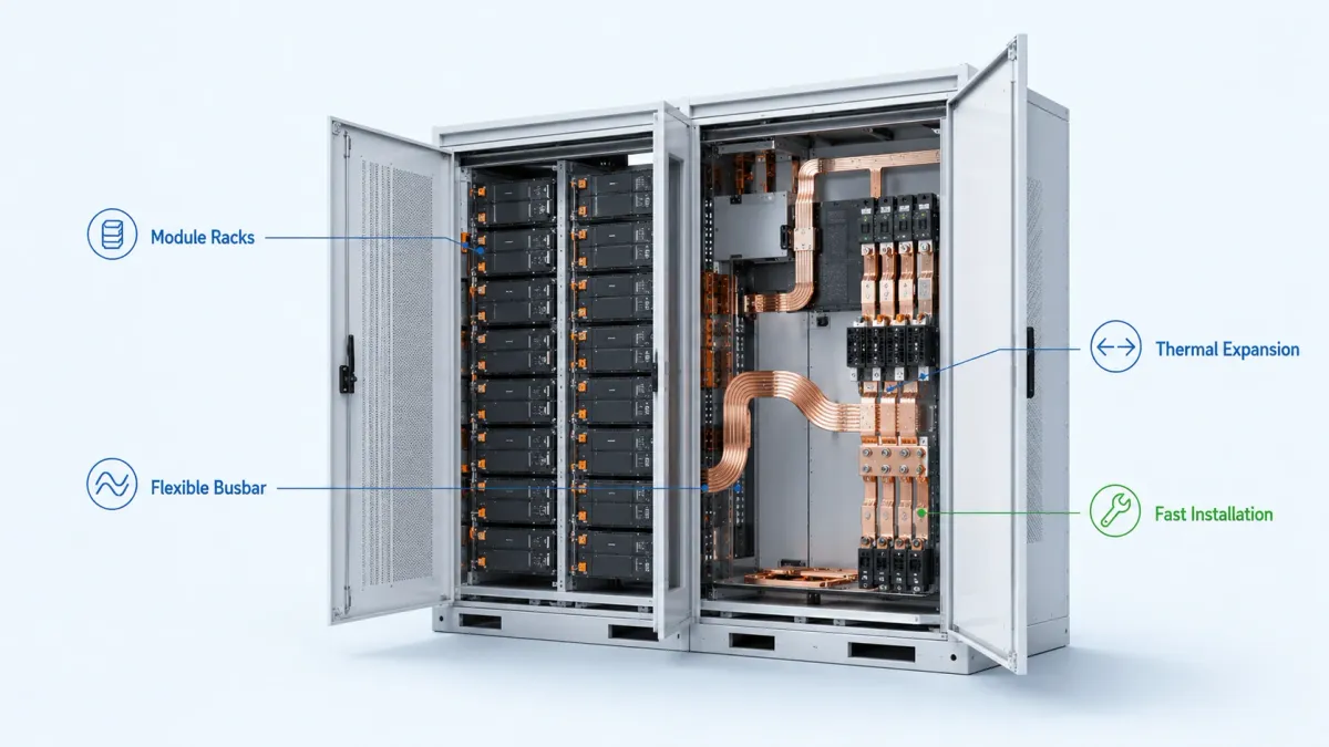
Thermal design for battery packs and BESS
Battery packs and BESS racks introduce thermal problems that are different from traditional switchgear. In a battery pack, current paths may be close to cells, sensors, plastics, adhesives, cooling plates and BMS wiring. In a BESS cabinet, busbars may sit near contactors, fuses, shunts, terminal blocks, PCS interfaces and air channels. In both cases, the conductor may be insulated, which protects against touch and short circuits but reduces direct heat dissipation.
A flexible busbar designer should evaluate three thermal zones. The first is the flexible body. This zone is usually long enough to dissipate heat across its surface. A flat laminated busbar may cool better than a round cable because it has more exposed surface area for the same conductor cross-section. The second zone is the transition from flexible body to terminal. This area can become a stress and heat concentration point if the bend starts too close to the welded pad or if the copper layers are not properly consolidated. The third zone is the contact interface. Many field issues that are described as “busbar overheating” are actually contact-resistance issues caused by poor surface finish, insufficient torque, washer stack problems, oxidation, contamination or inadequate overlap.
For battery packs, the busbar temperature should be considered together with cell temperature limits. A copper conductor may be able to run hotter than the cell or nearby polymer parts. That does not mean the assembly should allow it. A hot busbar can heat adjacent cells, soften insulation, accelerate aging or create misleading BMS temperature readings.
For BESS, service life is a major concern. A utility-scale or commercial storage system may be expected to operate for many years with repeated charge-discharge cycles. A slightly oversized busbar can reduce losses and heat, which may improve long-term reliability and operating efficiency. The best economic design is not always the smallest copper area that passes a short test. In high-utilization systems, lower resistance can reduce lifetime energy loss and thermal stress.
Voltage, insulation, creepage and clearance
Flexible busbar design must treat voltage spacing as seriously as current. EV packs, BESS racks and DC fast chargers often operate at high DC voltages. A higher voltage can reduce current for the same power, but it increases insulation coordination requirements and makes creepage, clearance and surface contamination more important.
Clearance is the shortest distance through air between conductive parts. Creepage is the shortest distance along an insulating surface. Solid insulation is the material barrier between conductors. Standards and product safety teams use these concepts to reduce the risk of arcing, tracking and insulation breakdown. IEC 60664-1 is widely used as a basis for insulation coordination in low-voltage equipment up to AC 1,000 V or DC 1,500 V, including guidance for clearances, creepage distances and solid insulation (IEC 60664-1 overview). UL 840 similarly addresses insulation coordination, including clearances and creepage distances for electrical equipment (UL 840).
In practical flexible busbar design, insulation should not be added only at the end. The part geometry should leave enough space around holes, bends, weld areas and edges for insulation to remain continuous after forming. If heat-shrink tubing is used, designers should confirm how it behaves at bends and whether it creates wrinkles or thin spots. If epoxy powder coating, PVC dipping or PA-style insulation is used, the team should define coating thickness, mask areas, edge coverage and dielectric testing method. JUMAI’s Custom Copper Busbars page lists heat shrink tubing, PVC dipping and epoxy powder coating as available insulation options, and also notes surface finish choices such as tin, nickel and silver plating.
The buyer should provide the voltage class, pollution degree or environment description, altitude, insulation requirement, flame rating requirement and any customer-specific creepage/clearance rules. If the busbar will be installed in a sealed battery pack, the environment is different from an outdoor BESS cabinet exposed to humidity and dust. If the busbar is used near a cooling plate or metal enclosure, mechanical clearance must include assembly tolerance and vibration movement, not just CAD nominal distance.
Vibration and movement are design loads
In high-vibration systems, a flexible busbar should be viewed as a mechanical component as much as an electrical conductor. EV battery packs face road-induced vibration, shock events, chassis movement and thermal cycling. BESS modules may experience transport vibration, installation handling, HVAC fan vibration and seismic requirements in some regions. Industrial drives, generators, rail systems and marine power equipment add their own vibration profiles.
IEC 60068-2-6 describes sinusoidal vibration testing intended to identify mechanical weakness or performance degradation and can be used to demonstrate mechanical robustness or study dynamic behavior (IEC 60068-2-6). SAE J2380 is a recommended practice for vibration durability testing of electric vehicle batteries (SAE J2380). Lithium battery transportation requirements also include vibration as part of UN Manual of Tests and Criteria Section 38.3 (UN 38.3 lithium battery testing).
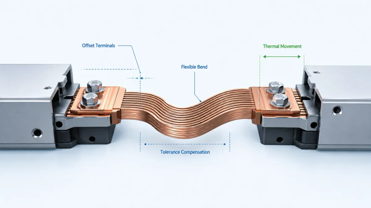
A flexible busbar does not replace system vibration validation, but it can reduce the risk that vibration loads are transferred directly into cell tabs, terminals, contactor studs or PCB-mounted power devices. The flexible region should be placed where movement is expected. The bend radius should be large enough for the copper construction. The terminal should not be asked to flex. Holes should not be too close to bend transitions. Sharp internal corners should be avoided. Copper layer edges should not cut into insulation during vibration.
A common mistake is making the flexible section too short. A very short flexible busbar can be flexible during hand installation but still too stiff under vibration. Another mistake is bending the busbar at the edge of the welded pad. The weld or pressed terminal region is meant to create a stable electrical joint. Repeated flexing at this boundary can create fatigue risk. The design should include a defined transition length between the solid terminal and the active bend zone.
Battery pack design: from cell module to high-voltage junction box
In EV and mobile battery packs, flexible busbars may connect modules, contactors, fuses, pyrofuses, service disconnects, current sensors, shunts, HV connectors and power electronics interfaces. The pack is mechanically complex. Cells can expand slightly during cycling. Modules have tolerances. Cooling plates, end plates and enclosures move at different rates. The vehicle structure adds vibration. A rigid connection can force these movements into terminals.
A laminated flexible busbar is often suitable when the connection must carry high current in a low-profile path. It can be shaped to follow a defined route above or beside modules. It can be insulated except for contact pads. It can include formed bends to clear adjacent components. A braided busbar may be better where multi-directional motion is expected or where a ground/bonding strap must tolerate movement.
For battery pack design, several details matter early:
- Terminal stack-up: Define bolt size, washer type, nut plate, torque, contact area and plating compatibility.
- Insulation windows: Decide which areas must remain bare for electrical contact and which must be coated.
- Bend direction: Confirm whether the busbar will be bent before delivery or during assembly.
- Service movement: Consider whether the part will be removed during maintenance.
- Thermal neighbors: Identify cells, plastics, seals and sensors near the copper path.
- High-voltage safety: Confirm clearance, creepage, dielectric test and color identification requirements.
JUMAI’s article on Key Design Specifications for Flexible Copper Busbars in Electric Vehicles correctly frames the busbar as an engineered subsystem rather than a commodity strip of copper. That is the right mindset for battery packs. The busbar should be reviewed together with the pack CAD, not after all other parts are frozen.
BESS design: rack repeatability, safety documentation and field service
Battery energy storage systems create a different set of priorities. A BESS is often modular: cell, module, rack, cabinet, container, PCS, transformer and grid connection. A flexible busbar may be used between modules, within racks, inside DC combiners, between fuses and contactors, or at the PCS interface. The conductor must support electrical performance, but it must also support installation and maintenance.
UL 9540 covers electrical, electrochemical, mechanical and other energy storage technologies for systems intended to supply electrical energy, including review of charging and discharging, protection, control, communication and other system aspects (UL Energy Storage System Testing and Certification). UL 9540A is a test method for evaluating thermal runaway fire propagation in battery energy storage systems (UL 9540A). IEC 62933-1:2024 defines terminology for electrical energy storage systems, including terms needed for unit parameters, test methods, planning, installation, operation, environmental and safety issues (IEC 62933-1:2024).
These standards do not tell the busbar manufacturer every geometry detail, but they affect the documentation environment around the product. A BESS customer may need material traceability, plating specifications, insulation test records, dimensional inspection reports and sample validation. The busbar should not be treated as an anonymous copper strip. It is part of the safety and reliability file.
For BESS field service, flexible busbars can also reduce human error. If each busbar has a unique shape, hole pattern and insulation window, it can guide correct assembly. A flat pre-formed conductor is easier to inspect than a heavy cable routed behind several components. Color-coded insulation and marked polarity can help technicians avoid mistakes. When a design is repeated across hundreds or thousands of racks, this matters.
High-vibration power systems beyond EVs
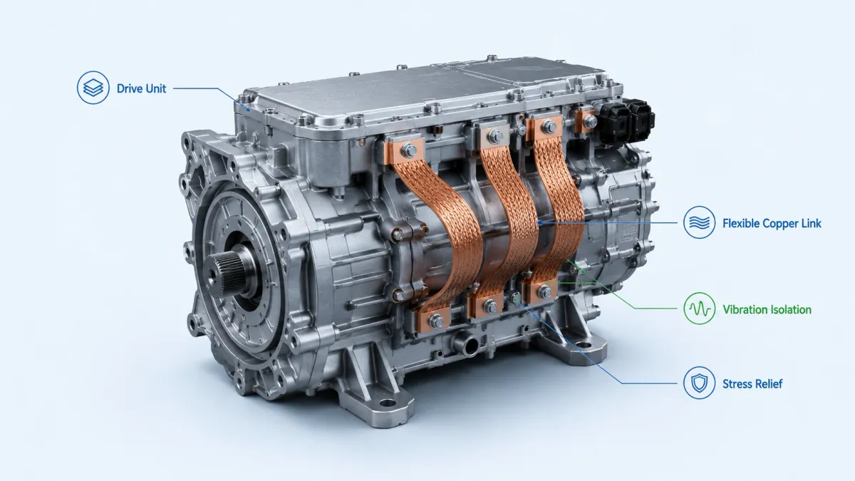
High-vibration power systems are not limited to vehicles. Rail equipment, marine power systems, industrial motors, generators, compressor drives, mining equipment, mobile charging systems and rotating machinery all create conductor stress. In these applications, flexible busbars are often used to bridge between a vibrating component and a fixed structure.
The decision between laminated and braided construction should be based on movement direction. Laminated copper foil busbars are excellent for controlled bends and compact routing. They are often best when the motion is small and predictable. Braided copper busbars are better for multi-axis movement, repeated flexing and bonding connections. A braided strap can tolerate small positional changes without forcing the terminals into alignment.
For harsh environments, plating selection becomes more important. Tin plating is widely used for oxidation resistance and solderability. Nickel plating is useful for higher temperature or harsher environments. Silver plating can reduce contact resistance in demanding contact applications but is more expensive and may require special handling. The plating choice should match the mating surface. Tin-to-tin, nickel-to-nickel and silver-to-silver interfaces behave differently under heat, humidity and bolted pressure. Mixed-metal interfaces should be reviewed for galvanic compatibility and contact stability.
Selecting the right flexible busbar construction
No single flexible busbar construction is best for all applications. The best design depends on current, voltage, space, movement, heat, cost, assembly method and validation requirements.
| Construction type | Best-fit applications | Main advantages | Design cautions |
|---|---|---|---|
| Laminated flexible copper busbar | EV battery packs, BESS racks, power cabinets, compact DC links | Low profile, predictable geometry, high current in flat path, controlled bend zones | Bend radius, layer count, welded terminal quality and insulation edge coverage must be controlled |
| Diffusion-bonded laminated busbar | High-current battery links, high-vibration power modules, premium compact assemblies | Solid terminal pads, low contact resistance potential, clean transition from flexible to solid areas | Requires precise tooling, process control and clear drawings for bonded zones |
| Braided copper busbar | Grounding straps, cabinet doors, rail/marine vibration links, transformer links, plating lines | Excellent multi-axis flexibility, vibration absorption, easy compensation for misalignment | Braid cross-section, terminal compression and strand protection must be specified |
| Soft copper link | Simple offset links, moderate vibration, cost-sensitive custom interconnects | Easy forming, lower complexity, good for short custom links | Not as controlled as laminated foil for tight packaging or repeated flexing |
| Rigid copper busbar with flexible section nearby | Switchgear, power distribution, large cabinets with one movement interface | Combines structural positioning with compliance where needed | Avoid using the rigid section to force alignment; place compliance where movement occurs |
The practical selection process should begin with the problem to be solved. If the issue is only package space, a laminated busbar may be ideal. If the issue is multi-axis vibration, a braid may be safer. If the issue is a fixed high-current path with minor installation tolerance, a rigid bar plus a short flexible link may be the best compromise. JUMAI’s ability to produce rigid, laminated flexible and braided busbars allows the design discussion to focus on the application rather than forcing every project into one product category.
Material grade, copper temper and layer design
Most high-current flexible busbars use high-conductivity copper such as T2/C11000. Copper grade matters, but temper and geometry also matter. Annealed copper is easier to bend and better for flexible sections. Harder copper may be useful for rigid features but can increase bending stress. In a laminated busbar, thinner layers usually improve flexibility, while more total copper area increases ampacity. The designer must balance electrical performance, flexibility and terminal thickness.
Layer count affects both performance and manufacturing. A stack of many thin foils can be more flexible than a few thick strips with the same total cross-section. However, too many layers can increase process complexity, terminal welding requirements and edge management. The end region must be consolidated well enough to behave like a solid pad under bolting. If the terminal is not stable, heat can build at the joint.
The copper edges should be deburred and controlled. Edge burrs can damage insulation, concentrate electric fields and create handling risk. In high-voltage busbars, edge radius and coating coverage deserve attention. A rounded edge is often better than a sharp edge for insulation reliability.
Plating and surface finish
Surface finish affects oxidation resistance, contact resistance and environmental durability. Bare copper has excellent conductivity, but it oxidizes. Copper oxide may not be a major issue in every application, but in bolted joints, humid environments or field-service applications, plating is often preferred.
Tin plating is a common default for many busbar applications because it offers good oxidation resistance and reasonable cost. It is widely used in automotive, industrial and battery systems. Nickel plating is selected when temperature, wear or harsh environments are more demanding. Silver plating is used when contact performance is critical and the project can justify higher cost.
The design team should specify plating thickness, masked areas, adhesion requirements, salt spray or corrosion requirements if applicable, and whether plating occurs before or after forming. If the busbar is insulated, plating may still be needed at exposed terminals. The interface between plating and insulation must be clean and repeatable.
Insulation choices for flexible busbars
Insulation protects against accidental contact, short circuit, tracking and arcing. It can also provide color identification and mechanical protection. Common options include heat-shrink tubing, PVC dipping, epoxy powder coating and engineered polymer coatings. Each has trade-offs.
Heat-shrink tubing is flexible, widely available and easy to apply, but it may not cover complex geometry as cleanly as a coating. PVC dipping can cover complex shapes and edges, but thickness control and masking must be managed. Epoxy powder coating can provide robust coverage and good dielectric properties, but bend areas and edge coverage require process validation. For high-voltage battery systems, insulation design should be reviewed with the full system safety requirement rather than selected only by appearance.
The RFQ should include dielectric test voltage, coating thickness, color, flame rating, adhesion requirement, exposed copper window size and acceptable cosmetic criteria. If the part will be bent after coating, that should be stated. Some coatings tolerate post-forming better than others. If the busbar is formed before coating, the coating process must reach all critical surfaces.
Design for manufacturability: the difference between CAD and production
A flexible busbar drawing should be easy to manufacture, inspect and assemble. CAD can create shapes that are theoretically possible but difficult to produce consistently. Early DFM review reduces risk.
Important DFM items include hole-to-edge distance, bend radius, flatness tolerance at terminals, hole positional tolerance, copper layer alignment, terminal pad thickness, burr direction, plating mask, insulation mask and packaging. For high-current bolted joints, flatness around the hole matters. If the pad is not flat, contact pressure may be uneven. If the hole is too close to a bend, the bolt stack may sit on a distorted surface.
JUMAI’s Custom Copper Busbars page describes a workflow from drawing evaluation to rapid prototyping, mass production and quality control. This is important because flexible busbar projects often need iteration. A prototype may fit electrically but reveal assembly interference. A coating may pass dielectric testing but need a larger mask window. A bend may need a small adjustment to avoid a bracket. The best supplier is one that can support these iterations quickly and document the final revision.
JUMAI also provides Deep Drawn Components and related tooling capabilities. For battery and power-system projects, this can be useful when the busbar is part of a broader assembly that also needs covers, shields, terminal housings, spacers, brackets or custom stamped parts.
Quality control and validation plan
A business-oriented busbar specification should include a clear quality plan. The required depth depends on application risk, but common checks include incoming copper material verification, dimensional inspection, hole position measurement, bend angle inspection, flatness inspection, plating thickness test, coating thickness test, dielectric withstand test, continuity test, contact-area visual inspection and packaging inspection.
For samples, the customer may also perform temperature-rise testing under actual enclosure conditions. This is more useful than relying only on free-air ampacity tables. The test should include the real terminal hardware, torque, washers, surface finish, airflow and nearby heat sources. Thermal imaging can identify hot spots at terminals and transition zones. If the application is vibration-prone, vibration testing should use the actual mounting method and check resistance before and after the test.
For BESS and EV projects, documentation can include material certificate, RoHS/REACH statements if required, plating report, coating report, dimensional report and first article inspection. For recurring production, the drawing should define critical-to-quality dimensions and acceptance criteria.
RFQ checklist for a custom flexible busbar
A good RFQ helps the supplier respond with a manufacturable proposal instead of guessing. The following checklist can be used by engineering, sourcing and project teams.
| RFQ item | What to provide | Why it matters |
|---|---|---|
| Application | EV pack, BESS rack, UPS, charger, data center power shelf, rail, marine or industrial equipment | Allows the supplier to understand vibration, thermal and regulatory expectations |
| Electrical load | Continuous current, peak current, duty cycle, voltage, short-circuit or fault requirement | Defines copper cross-section, terminal design and validation needs |
| Geometry | 2D drawing, 3D STEP file, bend direction, installation envelope, keep-out zones | Prevents fit issues and supports DFM review |
| Copper material | T2/C11000, oxygen-free copper if required, temper requirement | Affects conductivity, bending and cost |
| Construction | Laminated, diffusion-bonded, braided, soft link or open to supplier recommendation | Helps match movement and packaging needs |
| Terminal design | Hole size, slot size, pad thickness, contact area, torque, mating material | Controls contact resistance and mechanical reliability |
| Surface finish | Bare copper, tin, nickel, silver or mixed requirement | Protects against oxidation and supports stable contact behavior |
| Insulation | Heat shrink, PVC, epoxy powder, color, thickness, dielectric test, flame rating | Ensures safety and assembly identification |
| Environment | Ambient temperature, enclosure temperature, humidity, salt spray, vibration, altitude | Drives derating, plating, insulation and validation |
| Compliance documents | UL/IEC project requirements, material reports, RoHS/REACH, PPAP-like documents if needed | Supports customer certification and production approval |
| Quantity and schedule | Prototype quantity, pilot quantity, annual volume, target delivery | Helps select process, tooling and pricing strategy |
Cost drivers and how to control them
Flexible busbar cost is influenced by copper weight, layer count, tooling complexity, terminal process, plating, insulation, tolerance, inspection level and packaging. Buyers sometimes focus only on copper weight, but two busbars with the same copper mass can have very different manufacturing cost.
A highly complex 3D shape may require forming tools and careful inspection. A diffusion-bonded laminated busbar requires controlled bonding at terminal areas. A braided busbar requires terminal compression and strand control. Epoxy coating may require masking and dielectric testing. Silver plating adds material and process cost. Tight flatness and hole-position tolerances increase inspection and process control.
Cost can often be reduced without sacrificing performance by simplifying bend geometry, standardizing hole sizes, avoiding unnecessary cosmetic requirements, grouping similar parts, allowing supplier-recommended bend radii, and defining critical tolerances only where they truly matter. Another powerful cost-control method is early supplier involvement. If the busbar manufacturer reviews the concept before the battery module or cabinet layout is frozen, small changes can reduce tooling and inspection cost.
The cheapest conductor is not always the lowest-cost solution. If a flexible busbar reduces assembly time, eliminates rework, improves service access or lowers thermal loss, the total system cost may be lower even when the purchased component price is higher.
Common design mistakes
One common mistake is selecting copper cross-section by current only. Current matters, but so do enclosure temperature, insulation, airflow, contact resistance and duty cycle. Another mistake is placing bends too close to holes or welded terminals. This creates stress where the design needs stability. A third mistake is ignoring assembly sequence. A busbar that fits in CAD may be impossible to install after the contactor, fuse or enclosure wall is already in place.
Insulation mistakes are also frequent. Designers may leave too little exposed copper around a bolt hole, causing the washer to sit partly on coating. Or they may leave too much exposed copper, reducing creepage distance. Another issue is sharp copper edges under coating. Even if the coating passes an initial dielectric test, a sharp edge can become a long-term weakness under vibration and thermal cycling.
For braided busbars, terminal compression is critical. Loose strands near the terminal can create heat and mechanical weakness. For laminated busbars, the consolidated terminal area must be properly defined and inspected. For soft copper links, the team should confirm that the part will not be repeatedly flexed beyond its intended movement range.
How JUMAI supports flexible busbar projects
JUMAI is positioned for custom busbar projects where the customer needs more than a catalog part. The company manufactures rigid copper busbars, soft/braided copper busbars and laminated flexible copper busbars. Its process capabilities include cutting, punching, CNC bending, cold pressing for braided terminals, diffusion welding for laminates, plating and insulation. The company also supports deep drawing, stamping dies and tooling components, which can be valuable when a power interconnect is part of a larger assembly.
For an OEM, pack integrator, BESS builder, charger manufacturer or power cabinet supplier, the best time to contact JUMAI is before the drawing is fully locked. A busbar drawing can usually be improved through DFM review. For example, a small change to the bend radius may improve forming repeatability. A larger terminal pad may reduce contact temperature. A revised insulation mask may improve creepage. A different plating selection may improve field durability. These changes are easier before tooling and certification samples are finalized.
The practical process is straightforward. Send 2D/3D drawings, current and voltage requirements, installation environment, surface finish needs, insulation requirements and expected volumes. JUMAI can review manufacturability, suggest construction options and support prototype development. For teams comparing cable, rigid busbar and flexible busbar options, JUMAI’s internal articles on flexible busbar vs. cable and rigid vs. flexible precision copper busbars can help align engineering and sourcing discussions.
Practical specification example
A typical BESS rack interconnect might be described like this:
- Application: indoor BESS rack DC interconnect between module output and rack fuse.
- Voltage class: 1,500 V DC system architecture, final creepage and clearance per customer safety design.
- Current: 250 A continuous, 400 A short-duration peak, duty cycle provided by customer.
- Construction: laminated flexible copper busbar, C11000/T2 copper, supplier to recommend layer count.
- Surface finish: tin-plated exposed terminals.
- Insulation: orange epoxy powder coating, exposed terminal windows only, dielectric test required.
- Mechanical: pre-formed bends, no field bending, installation tolerance ± specified value.
- Validation: dimensional report, plating thickness report, coating thickness report, dielectric test report, sample thermal test in customer enclosure.
An EV pack interconnect might be different:
- Application: module-to-HV junction box connection inside traction battery pack.
- Current: high peak current with fast-charge profile; customer provides current-time curve.
- Construction: diffusion-bonded laminated flexible copper busbar, low-profile route.
- Mechanical: vibration and thermal cycling expected; flexible zone must absorb module/enclosure tolerance.
- Insulation: high-voltage orange coating or sleeve, edge coverage controlled, flame rating requirement stated.
- Terminals: defined pad flatness, bolt size, torque, washer stack and mating surface plating.
These examples show why a useful busbar RFQ needs more than length, width and hole size. The supplier cannot optimize the design without understanding the system.
Frequently asked questions
Is a flexible busbar always better than a cable?
No. A cable is still useful for long routes, very free routing or applications where standard cable assemblies are sufficient. A flexible busbar is usually better when the project needs compact packaging, controlled current path, repeatable assembly, lower profile, defined insulation windows or reduced terminal stress.
Is a flexible busbar always better than a rigid busbar?
No. A rigid busbar is often better when the connection is static, well-supported and requires structural stability. A flexible busbar is better when there is vibration, thermal expansion, installation tolerance or movement between connected parts.
How do I estimate flexible busbar ampacity?
Start with current, copper cross-section and resistance, but also include ambient temperature, enclosure temperature, insulation, airflow, duty cycle and contact resistance. Ampacity tables are useful references, but final validation should be done in the real assembly when the application is high current or safety critical.
Which copper grade should I use?
T2/C11000 copper is widely used because it offers high conductivity and good manufacturability. For special applications, oxygen-free copper or other grades may be considered, but the benefit should be justified by the operating environment and process requirements.
What information should I send to JUMAI for quotation?
Send drawings or STEP files, current and voltage requirements, duty cycle, installation environment, movement or vibration conditions, preferred surface finish, insulation requirements, quantity, schedule and any standard or customer-specific validation requirement. If the design is not final, JUMAI can review it and suggest manufacturable options.
Make the conductor part of the system design
A flexible busbar is not just a bent copper part. In battery packs, BESS racks and high-vibration power systems, it is a mechanical, electrical, thermal and manufacturing interface. A good design carries current with low loss, protects terminals from stress, fits into limited space, supports insulation safety, survives vibration and simplifies assembly.
The growth of EVs, BESS and high-density power infrastructure makes this more important every year. As current paths become more compact and power systems become more modular, the conductor must be engineered with the same care as the battery module, contactor, fuse, cooling plate or enclosure.
JUMAI can support projects that require custom flexible busbars, rigid copper busbars, braided copper busbars and related precision metal components. If your team is designing a battery pack, BESS rack, data center power cabinet, EV charger or high-vibration electrical system, send your drawings and operating requirements for a manufacturability review. A well-designed flexible busbar can reduce assembly risk, improve thermal reliability and turn a difficult power connection into a repeatable production part.