Electric vehicle engineers are under constant pressure to do more with less: more current, more safety, more power density, more production consistency, and less space, less weight, less heat, and less risk. In that context, Flexible Copper Busbars have moved from being a helpful component choice to being a strategic design decision. They are no longer selected only because they bend. They are selected because they help battery packs, inverters, DC/DC converters, junction boxes, and charging interfaces survive the real operating conditions of modern EVs.
That shift is happening inside a market that is still expanding rapidly. According to the IEA Global EV Outlook 2025, global electric car sales exceeded 17 million in 2024, more than 20% of new cars sold worldwide were electric, first-quarter 2025 sales exceeded 4 million, and full-year 2025 sales are expected to pass 20 million. Those numbers matter to component designers because higher production volumes force every interconnect supplier to deliver not just conductivity, but repeatability, traceability, manufacturability, and cost control at scale.
For EV OEMs, Tier 1 suppliers, battery pack integrators, and charging-equipment designers, the busbar is a performance-critical part. A poor design can create localized heating, torque loss, contact resistance growth, insulation risk, vibration fatigue, assembly difficulty, and field failures that are expensive to diagnose. A strong design, by contrast, improves packaging freedom, long-term reliability, and throughput on the production line.
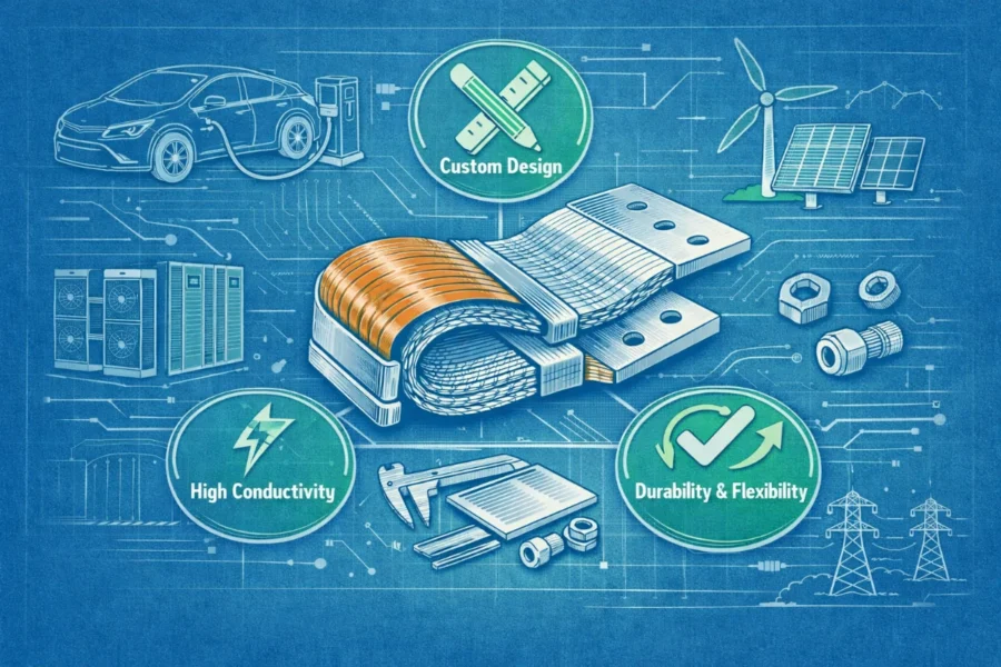
At JUMAI, we approach this topic from both sides of the problem: conductor performance and manufacturability. DeepDrawTech develops and manufactures custom soft, hard, and braided copper busbars together with precision metal forming, deep-drawn accessories, and related custom processing solutions. If you are planning a new EV electrical architecture, the best results usually come from treating the busbar as an engineered subsystem rather than as a commodity strip of copper. For readers who want a quick primer on JUMAI’s product families, the Soft & Rigid Copper Busbar Series is a useful starting point.
This article explains the key design specifications for Flexible Copper Busbars in EV applications in practical language. It is written for sourcing teams, product engineers, battery-pack designers, and technical buyers who need clear decision criteria rather than vague marketing claims. It also includes data tables, design formulas, standards references, and sourcing guidance so the article can support both SEO visibility and real commercial conversion.
Table of Contents
Why flexible busbar design matters more in EV systems than in conventional power equipment
A conventional low-vibration cabinet in a factory and a traction battery in a moving vehicle do not ask the same things from an electrical interconnect. EV applications combine several stresses at once:
- high DC current,
- repeated charge/discharge cycling,
- thermal expansion and contraction,
- road shock and vibration,
- tight packaging envelopes,
- strict insulation coordination,
- weight sensitivity,
- automated assembly requirements, and
- long service-life expectations.
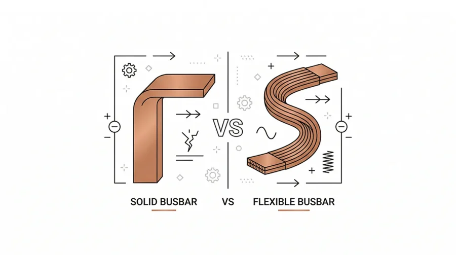
Rigid copper bars still make sense in some static sections of electrical architecture, but they can become liabilities wherever movement, tolerance stack-up, thermal breathing, or multi-axis installation constraints are present. That is one reason flexible constructions are increasingly favored in battery modules, pack-to-pack transitions, inverter connections, and vibration-prone high-current interfaces. JUMAI has also discussed this broader selection logic in its article on Flexible Copper Busbars vs. Solid Busbars: Which is Best for Power Transmission?.
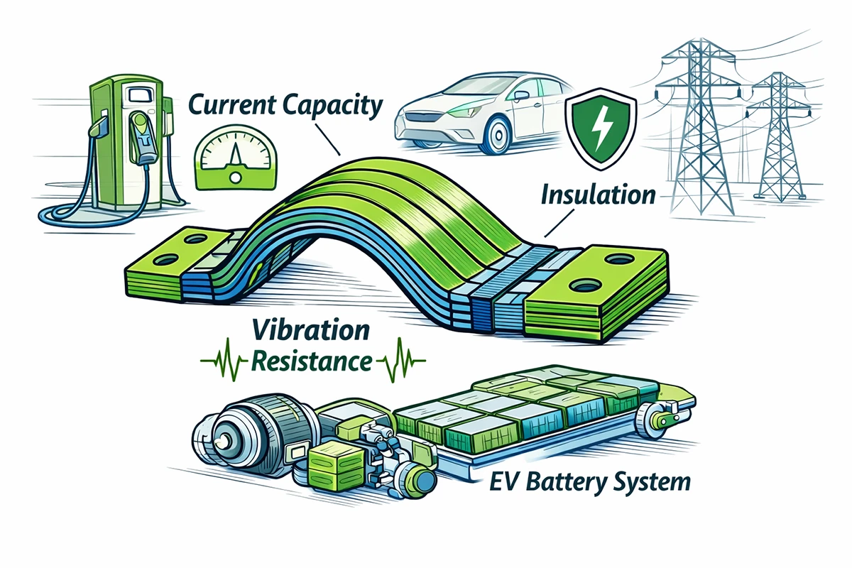
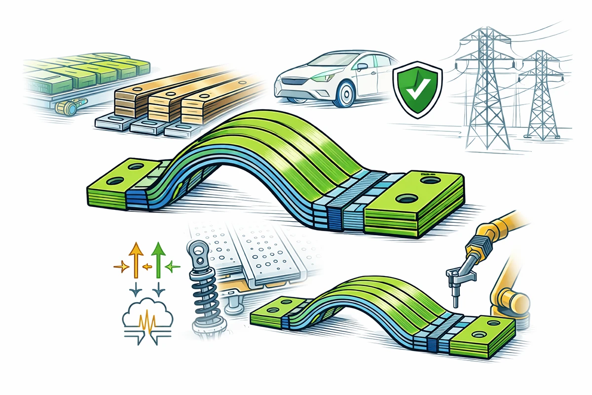
In EVs, the word “flexible” should not be mistaken for “weak.” A properly engineered flexible copper busbar is designed to remain electrically efficient while mechanically compliant. That compliance protects terminals, absorbs assembly mismatch, reduces transmitted stress, and simplifies routing. Depending on the construction, a flexible busbar can also improve thermal dissipation because multiple foils or braided strands expose more effective surface area than a single thick bar.
The commercial implication is straightforward: a slightly higher up-front engineering cost often lowers the total cost of ownership. Fewer joint failures, easier assembly, lower scrap during pack build, and better long-term stability usually save more money than the difference between a generic bar and an engineered flexible part.
What a flexible copper busbar actually is
A flexible copper busbar is a high-current conductor designed to transmit electrical power while allowing controlled movement. In EV systems, the most common flexible structures are:
- Laminated flexible busbars, built from stacked thin copper foils that are welded or press-bonded at the ends while the middle section remains free to flex.
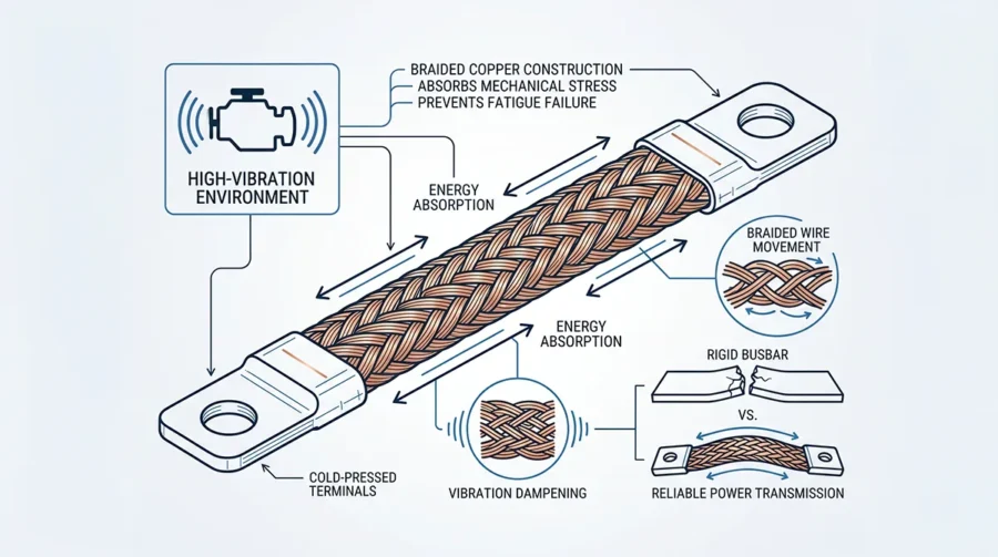
- Braided copper busbars, made from many fine copper wires woven into a braid, then compacted or cold-formed at the terminals.
- Insulated flexible assemblies, which add heat shrink, PVC, silicone, or other dielectric layers for touch safety, routing protection, and compliance support.
Each structure behaves differently. Laminated designs are often preferred when engineers want lower inductance, controlled bending planes, compact thickness, and clean repeatable geometry. Braided designs are often preferred when the application involves stronger vibration, multi-directional movement, or more forgiving installation in irregular spaces. JUMAI’s articles on How Braided Flexible Copper Busbars Improve Reliability in High-Vibration Environments and Advanced Manufacturing: The Production Process of Premium Flexible Copper Busbars explain these structural differences in more detail.
For EV buyers, the real question is not “Which type is better in general?” It is “Which type is better for this exact joint, current profile, vibration profile, packaging envelope, and manufacturing process?” Good suppliers will always push the discussion in that direction.
EV market and charging context: why current levels are pushing busbar design
The push toward higher charging power is reshaping conductor design throughout the EV ecosystem. The National Renewable Energy Laboratory (NREL) classifies direct-current fast chargers for light-duty vehicles in the 150 kW to 350+ kW range. As charging power rises, the relationship between system voltage and current becomes impossible to ignore, because current drives conductor cross-section, heat generation, joint stress, and terminal size.
EV market and charging demand snapshot
| Industry indicator | Data point | Why it matters for busbar design |
|---|---|---|
| Global EV sales in 2024 | >17 million vehicles | Higher EV volume means more standardized, scalable interconnect demand |
| Share of new cars sold in 2024 that were electric | >20% | EV architecture is no longer niche; design for manufacturability matters |
| Global EV sales growth in 2024 | >25% YoY | Rapid growth increases pressure on supplier capacity and quality consistency |
| EV sales in Q1 2025 | >4 million vehicles | Near-term demand remains strong |
| Expected global EV sales in 2025 | >20 million vehicles | Component sourcing must be scalable and globally reliable |
| Typical DC fast charger range for light-duty vehicles | 150 kW to 350+ kW | Higher charging power pushes interconnect current and thermal requirements |
Source basis: IEA Global EV Outlook 2025, NREL charging infrastructure analysis.
Current required at different voltages
Using the basic electrical relationship I = P / V, it becomes clear why EV architecture choices matter so much for busbar sizing:
| Charging power | 400 V system | 800 V system | 1000 V system |
|---|---|---|---|
| 150 kW | 375 A | 187.5 A | 150 A |
| 250 kW | 625 A | 312.5 A | 250 A |
| 350 kW | 875 A | 437.5 A | 350 A |
This table is simple, but it tells an important engineering story. At the same power level, doubling voltage approximately halves current. Lower current can reduce conductor size, simplify thermal management, and lower resistive losses. But it also tightens demands on insulation coordination, creepage, clearance, and dielectric integrity. That is why a good EV busbar design process must balance both electrical efficiency and high-voltage safety rather than optimizing only one.
Core material specification: start with the right copper grade
If the application is a high-current EV interconnect, the copper grade is not a trivial purchasing detail. It is the foundation of conductivity, heat generation, formability, weldability, and long-term performance.
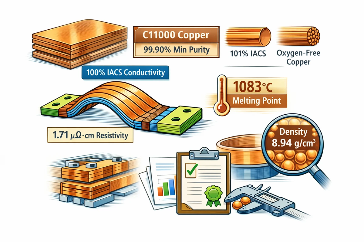
The Copper Development Association alloy database lists C11000 electrolytic tough pitch (ETP) copper at a minimum of 99.90% copper and a minimum conductivity of 100% IACS in the annealed condition. For many busbar applications, C11000 or equivalent high-conductivity copper is the practical industry baseline. In some specialized environments, oxygen-free grades may also be selected, but for mainstream EV busbar sourcing, the first commercial question is usually whether the supplier can consistently procure, certify, and process high-conductivity copper with the right temper and lot traceability.
Reference physical properties of high-conductivity copper
| Property | Reference value | Design significance |
|---|---|---|
| Copper purity for C11000 | 99.90% minimum | Supports high conductivity and predictable forming behavior |
| Electrical conductivity | 100% IACS minimum (C11000 annealed) | Reduces resistive loss and voltage drop |
| Electrical conductivity of massive copper | 101% IACS at 20 C reference conditions | Shows why pure copper remains the preferred commercial conductor |
| Electrical resistivity | 1.71 microhm-cm at 20 C | Critical for resistance and heating calculations |
| Thermal expansion coefficient | 17.0 x 10^-6 /C | Important for thermal cycling and stress analysis |
| Density | 8.94 g/cm3 | Matters when balancing weight and package size |
| Melting point | 1083 C | Useful as a materials reference, though far above operating range |
Source basis: C11000 data, Copper physical properties.
For procurement teams, one of the most important habits is to ask for material certification, not just verbal claims. A supplier should be able to support the copper grade, plating chemistry, foil thickness, braid specification, and terminal-processing route with inspection records and traceable production documentation.
Electrical design specifications that should be defined before requesting quotation
A large share of busbar problems start before the first sample is ever made. They start when the RFQ is too vague. If your drawing says only “flexible copper busbar” and basic dimensions, you are forcing the supplier to guess at the operating conditions. That usually leads to overdesign, underdesign, or repeated redesign.
At minimum, an EV busbar RFQ should define the following electrical parameters.
1. System voltage
The supplier needs the nominal DC voltage and the maximum operating voltage. This affects insulation selection, creepage and clearance review, surface finish selection, and terminal geometry. It also helps determine whether the busbar is being used inside a low-voltage control area, a traction battery subsystem, or a high-energy DC link.
2. Continuous current
Continuous current is the current the busbar must carry over sustained operation without exceeding the allowable temperature rise. This is the most important sizing parameter. It directly drives conductor cross-sectional area, foil stack count, braid density, palm size, and thermal management strategy.
3. Peak current and duration
An EV interconnect is rarely exposed only to steady-state current. Acceleration bursts, regenerative braking, pre-charge sequences, inverter transients, and charging pulses can all create short-duration current peaks. Those peaks do not always determine cross-section, but they must be defined because they influence joint design, fatigue, and localized heating.
4. Allowable temperature rise
Busbar sizing should never be discussed in current alone. It should be discussed as current under a specific thermal assumption. Many practical designs are evaluated around a defined ambient condition plus an allowable temperature rise. If one engineer assumes 30 C rise and another assumes 60 C rise, they may propose very different busbars for the same current.
5. Voltage drop target
When the application is high current, even a very small resistance increase can produce undesirable voltage drop and power loss. Define the acceptable voltage drop across the busbar or across the complete joint path. This is especially valuable when comparing bare, tinned, silver-plated, or different terminal-contact designs.
6. Short-circuit or fault withstand requirement
The busbar must survive not only normal operation, but also abnormal conditions. Short-circuit events create high electromagnetic force and thermal shock. If the design brief ignores fault current or protective-device coordination, the part may pass normal testing but still be too weak for actual system risk.
7. Frequency and switching environment
Most EV traction battery busbars carry DC, but that does not mean electromagnetic behavior can be ignored. In inverter-adjacent or high-speed switching environments, parasitic inductance, loop area, and EMI performance become more important. Laminated busbar structures are often chosen in these cases because their geometry can help reduce inductance.
Mechanical design specifications: where flexibility becomes real engineering value
Engineers often first notice flexible busbars because they solve routing problems. That is true, but only partially. The deeper value is that flexibility changes how mechanical stress flows through the system.
1. Required movement and axis of movement
Is the busbar meant to absorb assembly tolerance only once, or repeated movement over the vehicle’s life? Is the movement mainly in one plane, in torsion, or in several directions? Laminated foils behave differently from braids, so the supplier must know the real motion profile.
2. Minimum bend radius
A flexible busbar is not infinitely bendable. Foil thickness, number of layers, insulation, plating, and terminal compaction all affect the safe bend radius. Tight bends can create internal stress, insulation cracking, edge lifting, or uneven current distribution. If the package is compact, the supplier should be asked to recommend the practical bend radius before the tooling and validation plan are frozen.
3. Terminal alignment and hole position tolerance
Many field failures start at the terminal, not in the flexible middle section. Hole spacing, palm flatness, terminal thickness, and mating-surface finish all affect contact resistance and assembly quality. If a battery module design allows only small positional tolerance, the busbar must be designed to absorb mismatch without introducing installation stress.
4. Vibration and shock profile
Road vehicles impose real mechanical loads on electrical components. ISO 16750-3 addresses mechanical loads for electrical and electronic systems in road vehicles, while SAE J2380 is widely referenced for EV battery vibration durability. Even when a buyer does not require full automotive PPAP-style validation, vibration requirements should be stated early. That lets the supplier decide whether a laminated or braided design is the safer choice and whether terminal reinforcement or special strain relief is needed.
5. Assembly method
Will the part be hand-installed, robot-installed, or fixture-assisted? Is the torque sequence controlled? Is there risk of overtwist during installation? Can the operator see the terminal face clearly? Manufacturing questions like these matter because the best lab design is still a poor commercial design if it is easy to install incorrectly.
Thermal design specifications: electrical performance is never independent from heat
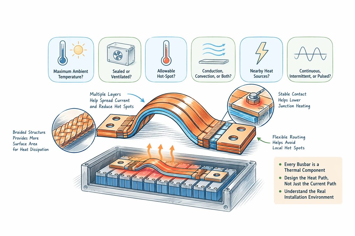
Every busbar is a thermal component. Current creates resistive heating, joints create localized heating, and enclosure conditions determine whether that heat leaves the system efficiently or remains trapped. For EV applications, thermal behavior should be reviewed at three levels:
- the conductor body,
- the terminal/joint interface,
- the surrounding enclosure environment.
Practical thermal questions to define
- What is the maximum ambient temperature near the busbar?
- Is the busbar inside a sealed battery pack, ventilated electronics box, or semi-exposed compartment?
- What is the allowable hot-spot temperature?
- Is heat mainly removed by conduction, convection, or a combination?
- Are there nearby heat sources such as power electronics, cells, contactors, or charging hardware?
- Is the duty cycle continuous, intermittent, or highly pulsed?
A busbar that performs well on an open bench may behave very differently in a sealed EV battery enclosure. That is why the best suppliers ask for the installation context rather than only the drawing.
Why flexible structures can help thermal behavior
In many cases, flexible structures improve heat handling in practice:
- laminated designs can spread current through multiple thin layers,
- braid structures provide more exposed surface area,
- flexible routing may keep the conductor away from hot spots,
- stress relief at the terminals can help maintain lower contact resistance over time.
None of that eliminates the need for proper thermal calculation, but it explains why flexible busbars are often preferred in compact high-current EV designs.
For engineers working on battery and energy-storage architecture more broadly, JUMAI’s article on The Role of Flexible Copper Busbars in Optimizing Battery Energy Storage Systems (BESS) gives a helpful cross-industry perspective. The thermal lessons from BESS, especially around sustained current and enclosure behavior, are often relevant to EV pack design as well.
Insulation coordination: one of the most overlooked design specifications
A surprising number of sourcing discussions spend too much time on copper thickness and not enough time on insulation coordination. In an EV, that is a mistake.
IEC 60664-1:2020 covers insulation coordination for equipment within low-voltage supply systems up to AC 1000 V or DC 1500 V and provides guidance on clearances, creepage distances, and solid insulation. Texas Instruments’ application guide on clearance and creepage for high-voltage equipment also provides a very clear practical explanation of the difference between the two:
- Clearance is the shortest distance in air between two conductive parts.
- Creepage distance is the shortest distance along the surface of a solid insulating material between two conductive parts.
In EV busbar design, both matter. Clearance matters because arcing risk is influenced by air distance, transient voltage, pollution, and altitude. Creepage matters because contamination, moisture, condensation, and material tracking resistance can turn a seemingly safe layout into a long-term reliability problem.
Material group and pollution degree are not paperwork details
The TI guide summarizes material groups by comparative tracking index (CTI), and it shows that pollution degree and material group materially influence creepage design. In practical terms, that means you cannot choose insulation purely by color, thickness, or price. You need to know whether the material is appropriate for the expected electrical stress and environmental exposure.
Altitude changes the design requirement
Altitude is another factor that many RFQs omit. IEC-based guidance assumes use up to 2000 m and provides correction guidance above that. An ABB application note referencing IEC 60664-1 shows altitude correction factors for clearance of 1.14 at 3000 m, 1.29 at 4000 m, 1.48 at 5000 m, and 1.70 at 6000 m. If the EV platform, off-highway vehicle, or charging equipment is expected to operate in high-altitude markets, the busbar insulation and spacing review should account for that at the design stage rather than after validation failure.
Reference altitude correction factors for clearance
| Altitude | Clearance correction factor (kd) |
|---|---|
| 2000 m | 1.00 |
| 3000 m | 1.14 |
| 4000 m | 1.29 |
| 5000 m | 1.48 |
| 6000 m | 1.70 |
Source basis: ABB application note summarizing IEC 60664-1 altitude correction factors.
For commercial buyers, the message is simple: if your vehicle or equipment has global deployment ambitions, ask the supplier whether the proposed busbar and insulation system has been reviewed for high-altitude operation.
Surface finish specification: bare copper, tin, nickel, or silver?
Surface finish is one of the most commercially misunderstood busbar specifications. Some buyers see plating as an optional cosmetic upgrade. It is not. It is a functional design choice that affects corrosion resistance, contact stability, mating behavior, and in some cases thermal and wear performance.
Bare copper
Bare copper gives very high conductivity and low initial material cost. It can be appropriate in protected environments with controlled interfaces, but it oxidizes over time. That oxidation can complicate storage, handling, and long-term joint stability if the mating process is not tightly controlled.
Tin plating
Tin plating is often the most balanced choice for EV and energy applications. It improves corrosion resistance, supports stable contact surfaces, and is commercially attractive. For many production EV programs, tin-plated terminals or fully tinned flexible assemblies offer the best combination of cost and field reliability.
Nickel plating
Nickel is harder and more wear-resistant than tin. It is often selected when temperature, abrasion, or harsher corrosion environments justify a more robust finish. The trade-off is that design and mating conditions must be reviewed carefully, because the plating choice changes contact behavior.
Silver plating
Silver provides excellent contact performance and is attractive for very demanding low-resistance interfaces, but it is usually reserved for higher-end or especially sensitive applications where the cost can be justified.
Finish selection guide
| Finish | Main advantage | Main trade-off | Typical fit |
|---|---|---|---|
| Bare copper | Lowest processing cost, very high base conductivity | Oxidation risk, storage and handling sensitivity | Protected internal systems with controlled assembly |
| Tin plated | Strong cost/performance balance, corrosion resistance | Slight added process cost | Mainstream EV, BESS, charger, inverter applications |
| Nickel plated | Hardness, wear resistance, higher-temperature robustness | More specialized selection and process control | Harsh or mechanically demanding environments |
| Silver plated | Very strong contact performance | Higher cost | Premium low-resistance or special-purpose interfaces |
Good suppliers should recommend finish based on environment, mating hardware, current level, storage conditions, and validation target – not simply on what they have in stock.
Terminal and joint design: where many busbar failures really begin

The flexible center of a busbar often receives the attention, but the terminals are where many failures are born. A busbar with excellent copper and poor joint design is still a poor busbar.
Key terminal specifications to define
- Palm dimensions and thickness The terminal must provide enough real contact area for current transfer and mechanical stability.
- Hole diameter and hole spacing These must match the mating hardware and torque strategy exactly.
- Flatness requirement Uneven palms increase micro-gaps, reduce real contact area, and raise contact resistance.
- Compaction or welding process For laminated or braided constructions, the transition from flexible body to solid terminal is critical. Poor compaction can trap voids, create nonuniform current flow, or weaken fatigue life.
- Edge condition and burr control Burrs are not just cosmetic defects. They affect assembly safety, insulation integrity, and joint quality.
- Contact resistance target If the application is high current, micro-ohm-level consistency matters. Ask how the supplier validates it.
- Mating interface material Copper-to-copper, copper-to-aluminum, and plated combinations behave differently. Galvanic and contact-performance considerations must be reviewed.
This is an area where integrated manufacturing capability becomes valuable. JUMAI’s page on Integrating Flexible Copper Busbars with Deep Drawn Stamping Accessories is relevant because many OEMs do not want only a conductor. They want a matched solution that includes formed terminals, brackets, protective hardware, and precision accessories that reduce assembly complexity.
Laminated vs braided flexible copper busbars in EV applications
There is no universal winner. The correct choice depends on the subsystem and the design priorities.
Laminated flexible busbars are often stronger when you need:
- controlled thickness and width,
- predictable bending behavior,
- compact low-profile package,
- lower inductance in power-electronics connections,
- clean repeatable geometry for mass production,
- easy insulation wrapping or lamination.
Braided flexible busbars are often stronger when you need:
- multi-directional flexibility,
- superior vibration absorption,
- easier installation in irregular spaces,
- tolerance for misalignment during assembly,
- softer mechanical coupling between components.
Subsystem-oriented selection guide
| EV subsystem | Common design priority | Usually favored flexible structure |
|---|---|---|
| Battery module interconnect | Thermal movement, packaging density, repeatable assembly | Laminated |
| Pack-to-pack or pack-to-junction transition | Mixed movement and current density | Laminated or braided, depending on space |
| Inverter or converter connection | Current, inductance control, compact routing | Laminated |
| Vibration-prone auxiliary high-current section | Mechanical isolation and multi-axis movement | Braided |
| Charger and service interface transition | Installation tolerance and serviceability | Braided or laminated, case dependent |
The right supplier should not force all applications into one product family. Instead, they should map the subsystem demands first.
Dimensions, tolerances, and stack-up: the specifications that affect manufacturability
One reason flexible busbar procurement turns into long back-and-forth email chains is that the first drawing often lacks the tolerance logic the supplier actually needs.
Dimensions that should be explicit
- overall length,
- terminal length at each end,
- active flexible section length,
- total width,
- copper thickness or foil stack definition,
- terminal thickness after compaction,
- hole quantity, size, and pitch,
- allowable twist or bend direction,
- insulation coverage area,
- exposed copper area,
- edge radius or chamfer needs.
Tolerance questions that should be discussed, not assumed
- How much length variation can the assembly accept?
- Is the hole position tolerance tighter than the body-width tolerance?
- Is terminal flatness more important than body thickness?
- Does the part need left/right handed orientation control?
- Will robotic assembly require camera-readable geometry or fixture datum features?
A supplier with real EV program experience will usually ask these questions early. That is a good sign. It means they are thinking about serial production, not just sample delivery.
Validation and quality-control specifications
A technically attractive quotation means little if the supplier cannot support repeatable quality. In EV applications, good busbar suppliers should be prepared to discuss both process control and validation evidence.
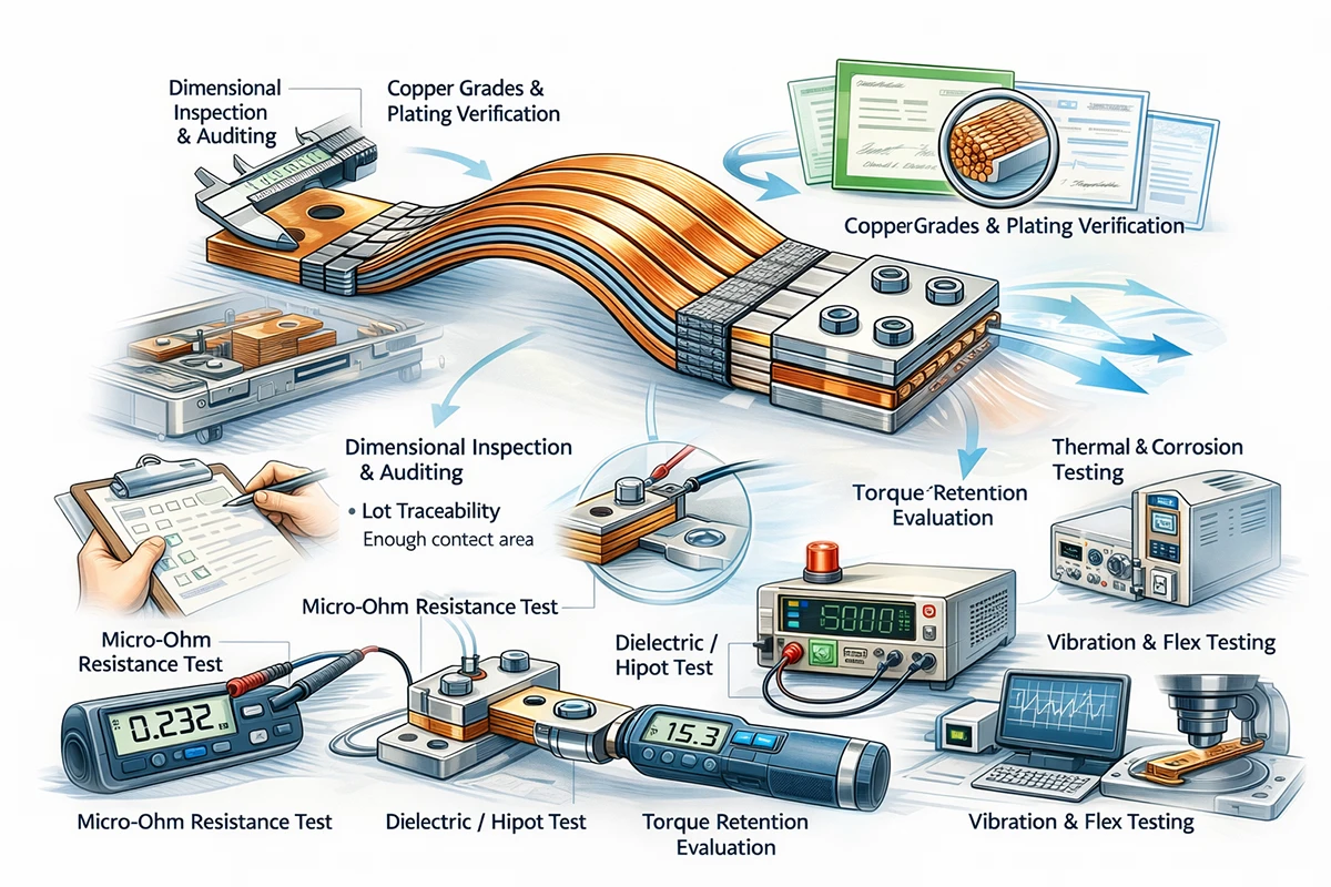
Typical validation items to review
- dimensional inspection,
- copper grade certification,
- plating thickness verification,
- micro-ohm resistance testing,
- dielectric or hipot testing for insulated versions,
- torque retention and joint evaluation,
- thermal rise testing,
- vibration testing aligned to program needs,
- bend-life or flex-cycle testing where relevant,
- salt spray or corrosion testing where relevant,
- cross-section checks at welded or compacted terminals,
- insulation adhesion and cut-through resistance.
Practical supplier questions
- Can you provide lot traceability for the copper and plating?
- What process is used to form the terminal ends?
- How is contact resistance measured and recorded?
- Do you validate samples only, or do you monitor production consistency as well?
- Can you support PPAP, APQP, or customized automotive documentation if required?
- How do you control burrs, cracks, delamination, or strand pullout?
- What is your corrective-action response process if a dimensional or electrical outlier is found?
This is also where process know-how matters. Buyers who want to understand how manufacturing quality is created, not just claimed, may find JUMAI’s article on the production process of premium flexible copper busbars useful.
Common design mistakes that create cost, delay, and reliability risk
In real projects, the biggest problems are rarely caused by a lack of copper. They are usually caused by incomplete design assumptions. Below are some of the most common mistakes.
Mistake 1: specifying only current and dimensions
Without voltage, ambient condition, duty cycle, insulation requirement, and vibration profile, the design is incomplete.
Mistake 2: ignoring the joint
A busbar body may be oversized while the terminals remain underspecified. That moves the risk to the interface.
Mistake 3: overfocusing on lowest piece price
A cheaper busbar that is harder to install, more prone to oxidation, or more likely to fail under vibration can easily become the more expensive option in full program cost.
Mistake 4: assuming a lab sample proves production readiness
A hand-finished sample and a mass-produced EV part are not the same thing. Ask about tooling route, process capability, inspection method, and scalability.
Mistake 5: forgetting service environment
High humidity, road salts, condensation, dust, altitude, and temperature cycling all influence finish and insulation choice.
Mistake 6: choosing flexibility without controlling movement
A flexible busbar should absorb intended movement, not flap freely. Uncontrolled motion can still damage adjacent components or insulation.
A practical RFQ checklist for EV flexible copper busbars
The table below can help engineering and procurement teams prepare a cleaner RFQ.
| RFQ item | Why it matters | Example of what to define |
|---|---|---|
| Application location | Determines risk profile and validation route | Battery module, inverter DC link, charger, junction box |
| System voltage | Drives insulation review | Nominal and maximum DC voltage |
| Continuous current | Primary sizing parameter | 350 A continuous |
| Peak current and duration | Impacts transient heating and joint design | 600 A for 10 s |
| Ambient and allowable temperature rise | Needed for thermal sizing | 85 C ambient, 35 C rise max |
| Vibration or shock requirement | Guides structure choice and validation | Vehicle-road profile or program standard |
| Busbar type preference | Helps supplier propose correctly | Laminated / braided / open for recommendation |
| Copper grade | Supports conductivity and traceability | C11000 or equivalent |
| Surface finish | Affects corrosion and contact behavior | Tin-plated terminals |
| Insulation type and coverage | Supports safety and packaging | Heat shrink over flex zone, exposed palms |
| Terminal geometry | Critical to fit and resistance | Hole diameter, pitch, palm width, thickness |
| Packaging constraints | Prevents redesign later | Bend envelope, max height, min radius |
| Validation requirements | Aligns supplier capability | Resistance, hipot, vibration, thermal rise |
| Documentation level | Important for automotive sourcing | Material certs, inspection reports, PPAP if needed |
A supplier can still help refine the details, but a structured RFQ saves time and reduces design risk dramatically.
Commercial considerations: what B2B buyers should really compare between suppliers
Many busbar quotations look similar on the surface. They list copper, size, plating, and price. That is not enough for a good supplier comparison.
Compare these five things instead
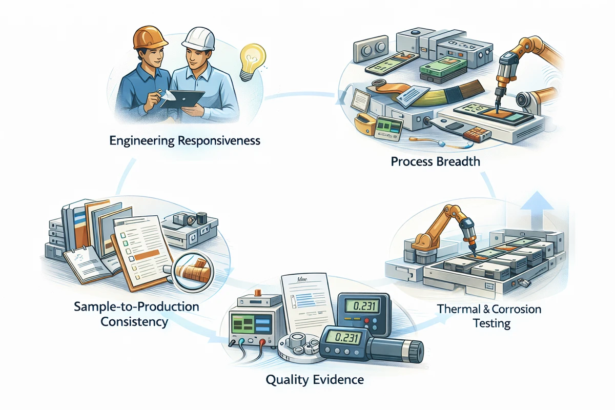
1. Engineering responsiveness
Did the supplier ask intelligent questions about current, vibration, insulation, and mounting? Or did they quote immediately with no technical challenge? In most cases, a technically curious supplier is the safer choice.
2. Process breadth
Can the supplier support only the conductor, or can they also support formed terminals, insulated versions, custom brackets, deep-drawn accessories, and related assembly parts? The broader the capability, the easier it is to reduce vendor complexity.
3. Sample-to-production consistency
Can the supplier explain how the sample route transitions into repeatable mass production? Tooling, inspection, and process control matter here.
4. Quality evidence
Look for real test data, process records, and dimensional discipline. Do not rely on generic statements like “high quality” or “strict QC.”
5. Program scalability
Can the supplier support pilot builds, design iterations, and later volume ramp-up without changing process stability?
This is exactly why many buyers prefer to work with manufacturers rather than simple traders. If the supplier understands both copper conduction and the forming/processing side of the hardware, the solution is usually stronger and the communication is much faster.
Why JUMAI is a practical partner for custom EV busbar projects
For business buyers, the ideal supplier is not the one with the longest catalog. It is the one that reduces uncertainty. JUMAI’s value is not limited to supplying a copper strip cut to size. The company’s broader manufacturing foundation – custom soft, rigid, and braided copper busbars together with precision deep-drawn parts, dies, and related accessories – allows project teams to solve interconnect problems as part of a wider assembly strategy.
That integrated capability matters in EV projects because the busbar often interfaces with more than one manufacturing discipline. The same program may require:
- high-conductivity copper processing,
- precision terminal forming,
- protective metal hardware,
- insulation treatment,
- assembly-friendly geometry,
- custom tolerances for compact systems,
- repeatable sourcing for global production.
For that reason, many OEM and Tier 1 buyers prefer suppliers who can support both electrical and structural integration. Readers interested in the sourcing and systems-level value of custom solutions can also review JUMAI’s article on the Top 5 Benefits of OEM Custom Flexible Copper Busbars for Global Projects.
Flexible copper busbars are not only an EV component – but EVs are one of the most demanding proving grounds
One useful way to assess a busbar supplier is to ask whether the same engineering logic works in other demanding sectors. EVs, battery energy storage, data centers, industrial converters, and renewable-energy equipment all value high current, tight space, thermal control, and reliability. If a supplier already serves adjacent high-performance industries, that usually strengthens their ability to support EV programs well.
DeepDrawTech’s homepage positions JUMAI around exactly that kind of cross-industry competence, including power connectivity for AI servers, EV systems, and energy equipment. That cross-application experience matters because it tends to create better judgment about heat, vibration, current density, insulation, and manufacturability.
Frequently asked questions about flexible copper busbar design in EVs
Are flexible copper busbars always better than rigid busbars in EVs?
No. They are better when the design includes movement, vibration, packaging difficulty, tolerance absorption, or high-current routing constraints that benefit from compliance. In static zones with simple geometry, rigid bars may still be the best choice.
Is laminated or braided construction better for battery packs?
Neither is universally better. Laminated designs are often preferred for compact, repeatable, controlled routing. Braided designs are often preferred where stronger vibration isolation or multi-axis flexibility is needed.
Is tin plating enough for EV applications?
In many cases, yes. Tin plating offers a strong practical balance of corrosion resistance, contact stability, and cost. But the right answer depends on environment, mating surface, current, storage conditions, and validation target.
Can a busbar be designed only from current rating?
No. Current rating without voltage, ambient temperature, duty cycle, movement profile, insulation requirement, and terminal geometry is not enough for a reliable design.
What causes busbar overheating most often?
Not just insufficient copper. Poor joint design, torque loss, oxidation, trapped heat, and unexpected duty cycle are all common causes of overheating.
What should buyers send to a supplier for a serious quotation?
At minimum: drawings or 3D data, voltage, continuous and peak current, ambient conditions, insulation needs, terminal requirements, validation expectations, and annual volume forecast.
Final takeaway
The best Flexible Copper Busbars for EVs are not selected by appearance or by copper thickness alone. They are selected by how well they satisfy a complete design brief that includes voltage, current, heat, movement, vibration, insulation, terminal behavior, manufacturability, and sourcing strategy.
If you are designing a battery module, traction pack, high-current charger interface, or compact EV power-distribution assembly, the most commercially effective approach is to define the busbar as a performance-critical custom part. That means choosing the right copper grade, the right flexible structure, the right plating, the right insulation system, the right terminal geometry, and the right supplier validation path.
As EV systems continue to move toward higher power, higher packaging density, and faster production cycles, busbar design will only become more important. The companies that treat interconnect design seriously will usually gain three advantages at once: stronger reliability, easier assembly, and lower lifecycle cost.
If your team is evaluating custom interconnect options now, JUMAI is well positioned to help with technical review, custom fabrication, and integrated hardware support. You can begin with the Soft & Rigid Copper Busbar Series, study the company’s engineering resources such as the Copper Busbar Ampacity Calculation Guide, and move into a project-specific discussion based on your real EV operating conditions.
In EV power architecture, the busbar should never be an afterthought. It is one of the places where electrical theory, mechanical reality, production practicality, and long-term commercial performance meet. When that component is engineered correctly, the entire system benefits.