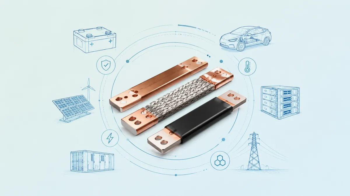
Battery bus bars are no longer simple pieces of metal hidden inside a battery pack. In electric vehicles, battery energy storage systems, charging equipment, industrial electrification, renewable power conversion and high-density backup power, the busbar is part conductor, part mechanical structure, part thermal path and part safety barrier. When it is designed correctly, it lowers resistance, reduces assembly complexity, saves space, improves serviceability and helps the battery system stay stable under vibration, thermal cycling and high current. When it is designed poorly, the same component can become a source of voltage drop, hot spots, insulation failures, terminal stress and field returns.
For buyers and engineers, the key question is not simply “What size copper bar do I need?” A better question is: Which battery bus bar architecture best fits the electrical load, mechanical movement, insulation requirement, production volume and assembly process of the product? The answer may be a rigid copper busbar for a stable pack-level connection, a laminated flexible copper busbar for a tight module bridge, a braided copper busbar for vibration isolation, a tinned copper busbar for corrosion resistance, or an epoxy-coated insulated busbar for a compact high-voltage layout.
JUMAI focuses on custom copper busbar manufacturing for exactly these practical decisions. The product family includes soft copper busbars, hard or rigid copper busbars, braided copper busbars, laminated flexible copper busbars, insulated bus bars and related precision metal parts. For a broader overview of JUMAI manufacturing capability, buyers can start with the Custom Copper Busbars service page, which describes high-purity T2/C11000 copper, rigid busbars, braided busbars, laminated flexible busbars, plating, insulation and drawing-to-delivery support.
This guide is written for OEM engineers, battery pack designers, procurement managers, power electronics teams and custom hardware buyers who need a practical, business-oriented way to specify battery bus bars. It covers copper materials, flexible and insulated options, common applications, design calculations, manufacturing choices, quality checks and the information a supplier needs before quotation.
- Why battery bus bars matter in new energy systems
- What is a battery bus bar?
- Copper as the preferred conductor for compact battery bus bars
- Main battery bus bar architectures
- Flexible battery bus bars: why they are used in EV and BESS packs
- Insulated battery bus bars: choosing protection without hiding risk
- Surface finishing: tin, nickel, silver and bare copper
- Electrical design fundamentals for battery bus bars
- Mechanical design: vibration, expansion and assembly tolerance
- Battery bus bars in EV battery packs
- Battery bus bars in BESS and stationary storage
- Battery bus bars for chargers, inverters and DC power equipment
- Manufacturing processes for custom battery bus bars
- Quality control and testing expectations
- How to specify battery bus bars for quotation
- Cost drivers: what makes one battery busbar more expensive than another?
- Copper busbar versus cable in battery systems
- Design examples for different new energy applications
- Common mistakes to avoid
- Why work with JUMAI for custom battery bus bars?
- Practical ordering workflow
- FAQ: battery bus bars for new energy applications
- Final thoughts
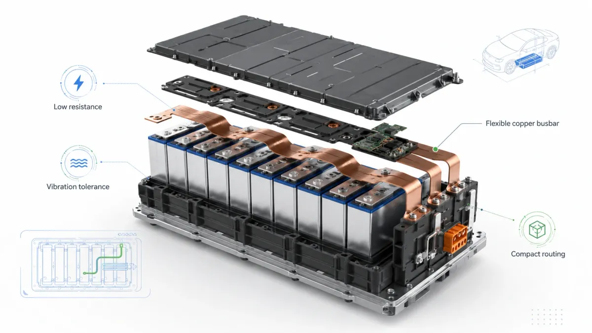
Why battery bus bars matter in new energy systems
The growth of battery-powered equipment is changing how current is routed. A decade ago, many low-voltage energy systems could be built with cables and simple terminals. Today, an EV battery pack or containerized BESS cabinet may need hundreds of precisely positioned current paths, multiple voltage domains, sensing tabs, fuses, contactors, shunts, thermal interfaces, grounding links and safety covers. Packaging density is higher, voltage is higher, current pulses are stronger and production teams need faster, repeatable assembly.
The market data explains why this design topic has become urgent. The International Energy Agency reported in its Global EV Outlook 2025 that electric car sales topped 17 million worldwide in 2024, rising by more than 25%, and that more than 20% of new cars sold globally were electric. China alone exceeded 11 million electric car sales in 2024. The same IEA analysis said the global electric car fleet reached almost 58 million at the end of 2024, more than triple the fleet in 2021. BloombergNEF’s Electric Vehicle Outlook further projects passenger EV sales to reach 23.3 million globally in 2026 and notes that public charging networks reached 6.7 million connectors in 2025. Each vehicle, charger, inverter, DC combiner and storage rack creates more demand for compact, reliable current distribution.
Battery storage is also expanding beyond vehicles. The IEA’s Batteries and Secure Energy Transitions report describes batteries as a critical technology for transport, power sector storage, utility-scale projects, behind-the-meter storage and decentralized power systems. In stationary storage, busbars must survive long operating life, repeated charge-discharge cycles, transportation shock, humidity, maintenance activity and sometimes outdoor enclosure conditions. Unlike a visible cable harness, an internal busbar is often difficult to replace after installation, so the design decision made at the prototype stage influences field reliability for years.
A battery bus bar must therefore do four jobs at the same time. It must conduct current with low resistance. It must manage heat by spreading losses and releasing heat to surrounding air, terminals or cooling structures. It must fit inside a defined mechanical envelope without overstressing cells, tabs, bolts or terminals. It must maintain insulation integrity under voltage, contamination, vibration and human handling. This combination makes busbar design a cross-functional engineering task rather than a simple purchasing item.
What is a battery bus bar?
A battery bus bar is a conductor used to connect battery cells, modules, racks, contactors, fuses, shunts, DC link capacitors, inverters, chargers or distribution nodes. The Copper Development Association describes busbar systems as bars of copper conductor that may be exposed or enclosed and may include joints and take-off points connected to end-use equipment. In battery systems, this idea becomes more specialized because the conductor must often connect components that expand, vibrate, move during assembly, or sit close to high-voltage neighboring parts.
The most common battery bus bars are made from copper or aluminum. Copper is preferred when the design requires high conductivity, compact size, reliable bolted contact, strong thermal spreading and predictable fabrication. Aluminum can reduce weight and cost in some larger structures, but it generally requires more cross-sectional area for the same resistance and demands careful attention to oxide layers, galvanic corrosion, contact plating and joint design. Many battery packs use a mix of metals: copper for high-current compact paths, nickel or nickel-plated parts for cell tabs and sensing, aluminum in cell terminals or module structures, and plated copper where contact stability is critical.
In a practical battery system, the word “busbar” may refer to several different parts:
- Cell-to-cell links in prismatic, cylindrical or pouch battery modules.
- Module-to-module bridges inside an EV battery pack.
- Pack-level high-voltage positive and negative conductors.
- Conductors between contactors, fuses, current sensors, shunts and service disconnects.
- BESS rack busbars and cabinet-level DC distribution bars.
- Grounding straps, bonding links and vibration-sensitive connections.
- DC busbars in chargers, inverters, DC/DC converters and power distribution units.
JUMAI’s battery busbar design guide explains why battery systems often combine rigid, laminated flexible, braided and hybrid busbar assemblies. A fixed path between two stable components may use a rigid copper busbar. A module bridge may need a laminated flexible copper busbar. A vibration-sensitive connection may use a braided copper busbar. A complex pack may combine rigid terminals, a flexible mid-section and plated contact zones.
Copper as the preferred conductor for compact battery bus bars
Copper remains the main material for many high-current battery bus bars because it delivers a strong combination of electrical conductivity, thermal conductivity, mechanical strength, ductility and manufacturability. The Copper Development Association explains that the International Annealed Copper Standard, or IACS, uses a reference copper conductor assigned a value of 100% conductivity, and that modern commercially pure copper can reach slightly better than 100% IACS due to improved refining. The International Copper Association also notes that pure copper has the best electrical and thermal conductivity of any commercial metal, which is why copper remains common in electrical and electronic applications.
For busbar purchasing, the material callout matters. ASTM International’s B187/B187M specification covers copper conductor bars, rods and shapes for electrical bus applications and general applications, including requirements related to dimensions, mechanical properties, electrical resistivity and chemical composition. JUMAI commonly works with high-purity T2/C11000 copper for custom copper busbars. C11000 electrolytic tough pitch copper is a practical, widely used choice for many busbar applications because it provides high conductivity and good fabrication behavior. Oxygen-free copper may be considered where welding, brazing, vacuum service or special high-temperature processing is important.
In battery bus bars, copper provides a compact path for high current. A simple resistance example shows why this matters. Using the standard resistivity of high-conductivity copper at 20°C, a 30 mm wide, 3 mm thick copper busbar has a cross-section of 90 mm². If the current path is 200 mm long, the approximate DC resistance is about 38 micro-ohms. At 300 A, that produces about 11.5 mV of voltage drop and about 3.4 W of heat. At 600 A, the voltage drop doubles to about 23 mV, while heat loss increases to about 13.8 W because I²R losses scale with the square of current. This is why a current pulse that appears acceptable electrically may still become a thermal design problem.
A busbar is not sized by cross-section alone. Real current-carrying capacity depends on ambient temperature, allowed temperature rise, insulation material, airflow, adjacent heat sources, contact resistance, plating, mounting method, duty cycle and whether the busbar is exposed or enclosed. JUMAI’s copper busbar ampacity calculation guide is a useful internal resource for understanding why ampacity is a thermal design question, not only a geometric question.
Main battery bus bar architectures
Battery bus bars can be grouped by mechanical behavior. The conductor may be rigid, laminated flexible, braided, soft formed, or hybrid. The right choice depends on whether the connection is static, whether the assembly must absorb movement, whether the route is space constrained and how accurately the final geometry must repeat in production.
| Battery bus bar type | Typical construction | Best fit in new energy equipment | Main advantages | Design cautions |
|---|---|---|---|---|
| Rigid copper busbar | Solid copper strip, plate or bar, cut, punched, stamped and CNC bent | Pack-level DC paths, switchgear, inverters, contactor-to-fuse links, BESS cabinet distribution | Predictable cross-section, strong mechanical positioning, good heat spreading, repeatable hole geometry | Requires accurate tolerance stack-up; may transfer vibration or thermal expansion stress into terminals |
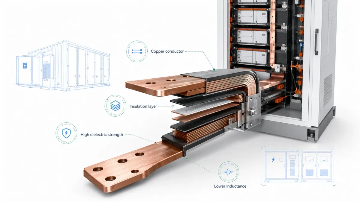
| Laminated flexible copper busbar | Multiple thin copper foils stacked together, joined at terminals and free to flex in the middle | EV module bridges, compact battery packs, inverter links, areas requiring bending or vibration relief | Compact routing, lower terminal stress, lower assembly force, high copper surface area | Must define foil thickness, foil count, bend zone, insulation, terminal weld/press quality and fatigue expectations |
| Braided copper busbar | Woven fine copper wires with cold-pressed, welded or plated terminals | Grounding links, vibration isolation, moving equipment, thermal expansion joints, high-vibration packs | Excellent multi-directional flexibility, absorbs movement, tolerant of misalignment | Geometry is less precise than solid bars; braid density, terminal compression and strand protection must be controlled |
| Soft formed copper busbar | Annealed copper strip or thin bar formed for moderate compliance | Short links with mild movement, serviceable battery assemblies, compact power boxes | Easier forming and installation than hard temper copper, can reduce assembly stress | Not as flexible as laminated or braided structures; bend radius and fatigue should be reviewed |
| Hybrid busbar | Rigid sections combined with flexible sections, welded terminals, sensing tabs or custom brackets | Complex EV packs, BESS racks, power distribution units with mixed constraints | Balances layout control and stress relief; can integrate multiple functions | Interfaces must be reviewed carefully; supplier needs 3D model and assembly sequence |
This table is a starting point, not a final specification. A rigid copper busbar can be the best engineering decision when the pack geometry is stable and the bar provides alignment, thermal spreading and predictable contact. A laminated flexible busbar is often better when the connection must absorb cell swelling, installation variation or thermal expansion. A braided copper busbar is often selected where vibration is more severe or movement is not limited to one plane. JUMAI’s article on rigid busbars vs flexible busbars explains these trade-offs in more detail for high-current systems.
Flexible battery bus bars: why they are used in EV and BESS packs
Flexible battery bus bars solve a problem that is easy to underestimate during early design. Battery modules are not perfectly fixed blocks. Cells expand and contract during cycling. Pack structures move under road vibration or shipping shock. Thermal gradients create small dimensional changes. Assembly tolerances accumulate. If a rigid conductor forces all movement into a cell terminal, weld nugget, threaded insert or contactor stud, the electrical design may be correct on paper but mechanically risky in service.
A laminated flexible copper busbar is typically made from multiple thin copper foils. The ends are consolidated by pressing, welding, diffusion bonding or another joining process so that the terminals behave like a solid contact area. The middle section remains flexible because the individual layers can slide slightly against one another. This structure allows the busbar to bend with much lower force than an equivalent solid copper bar. JUMAI’s flexible busbar for EV battery modules article describes how flexible busbars can help absorb micro-movements and road vibration inside EV packs.
A braided copper busbar uses many fine copper wires woven together. The braid provides flexibility in multiple directions and can absorb high-frequency vibration. It is especially useful for grounding, bonding, links to moving or vibrating components, or connections where installation alignment cannot be held tightly. Braided busbars can be bare, tinned, insulated, sleeved or supplied with solid terminals depending on current, environment and assembly method.
Flexible designs can also simplify assembly. A rigid busbar often requires holes to align very accurately with studs or threaded inserts. If the tolerance stack-up is too tight, production operators may need to force the part into place, which increases stress and rework. A laminated or braided flexible busbar can tolerate small misalignment, reduce bolt insertion force and improve production speed. In a high-volume battery pack, this can be a major business advantage because easier assembly reduces labor time, fixture complexity and quality risk.
However, flexible does not mean uncontrolled. Buyers should define the required current, voltage, bend direction, minimum bend radius, vibration environment, insulation system, terminal plating, terminal thickness, hole size, torque assumptions and expected life. A flexible busbar with an undersized weld area, a short flex section or poorly controlled insulation edge can fail just as quickly as a rigid busbar used in the wrong place.
Insulated battery bus bars: choosing protection without hiding risk
Insulation is one of the most important differences between a simple copper strip and a production-ready battery busbar. In a high-voltage battery system, copper must be protected from accidental touch, nearby conductors, grounded structures, vibration wear, coolant, dust, metal debris and service tools. At the same time, insulation must not interfere with the electrical contact area or trap too much heat.
IEC 60664-1 is widely used as a reference for insulation coordination in low-voltage electrical equipment. The standard scope includes equipment connected to low-voltage systems up to AC 1,000 V or DC 1,500 V and provides a framework for clearances, creepage distances and solid insulation. Battery pack engineers still need to apply the final requirements from the product standard, vehicle regulation and customer specification, but the principle is straightforward: voltage, pollution degree, material group, altitude and overvoltage category influence how much distance and insulation are required.
Several insulation options are common for battery bus bars. Heat shrink tubing is cost-effective and flexible, but it may be less suitable for complex 3D shapes if wrinkles or gaps appear. PVC dipping can cover complex geometries, but thickness control, edge quality and material rating must be managed. Epoxy powder coating provides a robust and uniform protective layer for many rigid and laminated busbars. PA12, PET, PI, silicone, TPE and molded covers may be selected when the product needs better abrasion resistance, higher temperature capability, tighter packaging or serviceable protection. JUMAI’s Custom Copper Busbars page describes heat shrink tubing, PVC dipping and epoxy powder coating as available insulation options, with flame-retardant formulations such as UL94 V-0 available depending on the project.
| Insulation or protection option | Where it is commonly used | Strengths | Watch points for battery bus bars |
|---|---|---|---|
| Heat shrink tubing | Straight or mildly formed flexible/rigid busbars, serviceable links | Cost-effective, quick, flexible, good for prototypes and moderate volume | Ends need clean sealing; complex bends can wrinkle; temperature and flame rating must be confirmed |
| PVC dipping or coating | Rigid busbars with complex shapes, formed bars, protective outer coating | Covers irregular geometry, good visual protection, useful for custom shapes | Thickness tolerance, pinholes, adhesion, edge buildup and contact mask accuracy need inspection |
| Epoxy powder coating | Rigid copper busbars, laminated flexible terminal areas, high-voltage distribution | Durable, uniform appearance, good dielectric protection and abrasion resistance | Sharp edges must be rounded; coating thickness and cure must be controlled; exposed contact zones need masking |
| PA12, PET, PI or high-performance film | EV battery modules, compact high-voltage spaces, thin laminated bars | Good dimensional control, thin insulation, suitable for compact packages | Film selection depends on temperature, abrasion, dielectric target and bending behavior |
| Silicone, TPE or elastomeric insulation | Flexible links, vibration-sensitive routes, areas requiring soft touch | Flexibility, vibration tolerance, good handling | Heat aging, chemical compatibility and tear resistance should be reviewed |
| Molded or assembled insulating cover | Service disconnects, contactor zones, high-voltage terminals, maintenance areas | Serviceable protection, strong touch safety, clear color coding possible | Adds tooling and assembly cost; must maintain creepage/clearance and not loosen under vibration |
Insulation design should begin before the copper shape is frozen. If the copper has sharp corners, insufficient edge radius or burrs, the insulation may thin out or crack. If the contact surface is not masked cleanly, coating may remain under the bolted joint and increase contact resistance. If the insulation extends too close to a bolt hole, the washer or terminal may damage it during tightening. If the insulation is too thick around a bend, it may reduce available clearance to neighboring components. These details are why a custom busbar should be reviewed as an electrical-mechanical-insulation assembly.
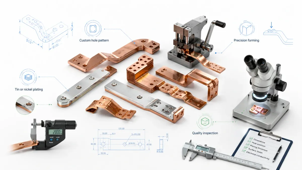
Surface finishing: tin, nickel, silver and bare copper
Surface finish is not a cosmetic decision. It affects contact resistance, oxidation behavior, corrosion resistance, solderability, weldability, temperature stability and compatibility with mating terminals. Bare copper has excellent conductivity, but it oxidizes in air. A thin oxide layer is not always a problem for a welded joint, but it can be a concern for bolted contacts, humid environments or products requiring long storage before assembly.
Tin plating is common for many power distribution busbars because it improves corrosion resistance and provides a practical contact surface at reasonable cost. It is widely used in BESS cabinets, low-voltage distribution, chargers and industrial power systems. Nickel plating is selected where higher temperature, wear resistance or harsher environmental exposure is expected. Silver plating provides excellent contact performance, especially in demanding high-current contacts, but cost is higher and the use case should justify the expense.
For battery bus bars, the finish should be specified by zone. A single part may have bare copper in a weld area, tin-plated terminals for bolted joints, nickel-plated surfaces near heat sources and insulated body sections. Mixed finishes are possible, but they need clear drawings, masking definitions and inspection criteria. The purchasing drawing should identify plating thickness, areas to be plated, areas to remain unplated, cosmetic acceptance, salt spray expectations if relevant and whether the part will be stored before assembly.
JUMAI’s copper busbar service page mentions tin plating, nickel plating, silver plating and bare copper options. For buyers comparing conductor materials and surface choices, JUMAI also maintains a practical internal resource on why copper is still preferred for high-current conductors and a busbar copper material guide that can be used as supporting reading during supplier discussions.
Electrical design fundamentals for battery bus bars
A battery busbar is often judged first by current rating, but current rating is not a single fixed value. The same copper cross-section can run cool in open air and hot inside an insulated, sealed enclosure near cells, contactors and power electronics. A design that works for a 10-second pulse may not be acceptable for continuous current. A busbar that passes a prototype test at 25°C may run too hot at 55°C ambient inside a cabinet.
The core design variables are straightforward:
- Continuous current: the current that flows for long periods under normal operation.
- Peak current: short-duration acceleration, fast-charge, fault-clearing or transient current.
- Voltage drop: the allowed loss across the busbar and its joints.
- Power loss: heat generated by the conductor and the contacts, calculated approximately as I²R.
- Temperature rise: the increase above ambient allowed by the product specification.
- Short-circuit withstand: the current and duration the part must survive during fault conditions.
- Contact resistance: resistance at bolted, welded, pressed or plated interfaces.
- Insulation voltage: dielectric withstand, creepage, clearance and touch-safety requirements.
Resistance begins with geometry. A longer current path increases resistance. A larger cross-sectional area decreases resistance. Copper temperature also matters because resistance rises as copper gets hotter. In a battery pack, heat may come from the busbar itself, the cells, the contactor, the fuse, the inverter, the charger or nearby coolant channels. A good busbar design gives heat a path to leave the conductor: through air, through terminals, through brackets, through a cold plate or through controlled contact with a thermal interface.
The contact area is often more important than designers expect. A beautiful copper body will still overheat if the bolted joint is small, uneven, oxidized, under-torqued, contaminated or coated in the wrong place. Contact resistance can dominate the total loss of a short busbar. This is why drawings should define hole tolerances, flatness, burr direction, plating, washer stack, torque assumptions and the mating material. For high-current joints, prototype testing should include temperature measurement at the joint, not only at the center of the copper bar.
Mechanical design: vibration, expansion and assembly tolerance
EV packs, mobile energy storage systems and industrial battery cabinets all experience mechanical stress. The stress may come from road vibration, shipping, forklift handling, thermal expansion, seismic loads, cell swelling or service operations. A busbar that is only checked for electrical resistance may fail mechanically if it transfers too much force into cell terminals or welds.
Common mechanical mistakes include hole positions that are too tight for the real tolerance stack-up, bend radii that are too small for copper thickness and temper, hole-to-edge distances that create cracks, undefined burr direction, flex sections that are too short, rigid bars used where thermal expansion requires compliance and insulation placed where the terminal must make electrical contact. JUMAI’s battery busbar design guide highlights exactly these types of production issues because they appear repeatedly in custom pack development.
The assembly sequence also matters. A busbar may look correct in CAD but be impossible to install after nearby covers, cooling plates or cell compression frames are in place. Bolts may be hidden behind a bend. A flexible busbar may need a specific neutral position before torque is applied. A braided strap may require a routing guide to avoid abrasion. An insulated busbar may need local protective film during assembly to prevent scratches.
A practical design review should ask: Can the operator install the busbar without bending it beyond its intended zone? Can the bolt be accessed with the specified tool? Does the busbar touch anything during vibration? Is there enough clearance after coating thickness is included? Is the flex zone long enough to absorb movement? Are copper edges rounded before insulation? Is there a service procedure for removal? These questions are not academic; they decide whether the product can be manufactured repeatably.
Battery bus bars in EV battery packs
In EV battery packs, busbars connect cells, modules and high-voltage distribution components while fitting into a thin, tightly controlled enclosure. The pack must resist vibration, shock, moisture, temperature changes and service handling. Weight matters, but so do voltage drop, thermal performance, crash safety and assembly speed. A busbar architecture that saves a few grams but creates assembly stress may not be a good trade.
Rigid copper busbars are often used for stable pack-level current paths between contactors, fuses, current sensors and service disconnects. These paths need predictable geometry and strong contact areas. Laminated flexible copper busbars are often used for module-to-module connections where some movement is expected. Braided copper busbars are useful for grounding, bonding or connections between vibrating subassemblies. Insulated busbars are common because high-voltage EV packs leave little room for accidental contact or uncontrolled creepage paths.
The transition to higher-voltage architectures increases the importance of insulation coordination. A nominal 400 V pack and an 800 V pack may have similar current in some areas, but the creepage, clearance, dielectric withstand and arcing risks are different. Engineers should not copy a low-voltage busbar layout into a high-voltage pack without rechecking spacing, insulation material, service covers and fault behavior. UL Standards & Engagement describes UL 2580 as covering safety aspects of EV battery system design, construction, installation and operation, including tests to help protect against electric shock, fire, mechanical and environmental hazards. This does not replace the OEM specification, but it shows why busbar insulation and mechanical integrity are part of battery safety.
For EV busbars, early supplier involvement is valuable. A busbar supplier can review whether the proposed copper thickness is realistic for bending, whether the terminal area is large enough for welding or bolting, whether insulation can be applied uniformly and whether a flexible design would reduce terminal stress. JUMAI supports these discussions with custom rigid, soft, braided and laminated flexible copper busbars, plus stamping and deep-drawn accessories when the pack needs special brackets, covers, terminals or metal features.
Battery bus bars in BESS and stationary storage
Battery energy storage systems have different design priorities from passenger EVs. Weight is usually less critical, but long life, serviceability, corrosion resistance, thermal stability and cabinet-level installation are extremely important. A BESS rack may operate through many cycles over many years. It may be shipped as a containerized unit, installed outdoors, exposed to humidity and serviced by technicians who need clear, safe access.
In BESS modules and racks, flexible copper busbars can absorb cell swelling, thermal expansion and transportation vibration. Rigid busbars are often used in cabinet-level DC distribution where geometry is stable and the busbar also acts as a structural power path. Tin plating is common for terminals because it provides practical oxidation resistance. Epoxy-coated or PVC-coated insulated busbars may be selected where conductors sit close to grounded metal frames or neighboring phases.
IEC’s IEC 62619:2022 specifies safety requirements and tests for secondary lithium cells and batteries used in industrial applications, including stationary applications such as telecom, UPS, electrical energy storage systems, utility switching and emergency power. Busbars are not the only focus of such battery safety standards, but their design contributes to safe operation because they affect short-circuit behavior, insulation integrity, heat generation and mechanical reliability.
JUMAI’s article on flexible copper busbars in battery energy storage systems explains why standard rigid connections can become inadequate in dynamic BESS environments. For buyers, the main lesson is simple: do not specify a BESS busbar as a flat copper strip only. Specify the actual operating environment, current profile, rack layout, service life, insulation requirement, plating requirement and assembly process.
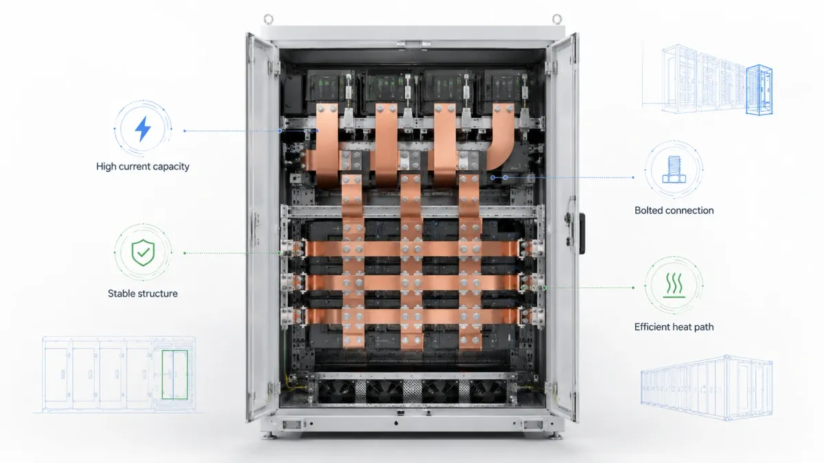
Battery bus bars for chargers, inverters and DC power equipment
New energy applications extend beyond the battery pack itself. Fast chargers, DC/DC converters, inverters, power distribution units, DC combiner boxes and AI data center backup systems also need compact current distribution. In these systems, busbars may connect capacitors, power modules, contactors, fuses, switches, circuit breakers and output terminals. The design goal is often to reduce inductance, save space, improve thermal performance and make assembly repeatable.
Flat copper busbars can reduce packaging volume compared with large cables. JUMAI’s flexible busbar vs cable comparison explains that flexible busbars are built from stacked thin copper strips and can be easier to route in tight enclosures than thick high-ampacity cables. In high-current chargers and inverters, a flat conductor can be routed close to the wall of an enclosure, paired with insulating barriers, or arranged as positive and negative layers to reduce loop area.
For power electronics, designers should also consider electromagnetic behavior. DC current has no AC skin effect in the same way as high-frequency AC, but switching currents and ripple currents can still create layout challenges. Keeping positive and negative paths close, reducing unnecessary loops and controlling contact geometry can help the whole power module behave more predictably. Laminated busbars, insulated layers and custom punched geometries can support these goals.
A custom busbar supplier must understand both the power requirement and the assembly requirement. The best design may not be the thickest bar. It may be a formed rigid busbar with a plated contact zone, a laminated flexible link to absorb tolerance, or a hybrid busbar that combines a rigid mounting area with a flexible section. JUMAI’s work in custom copper busbars, deep drawn components and tooling allows the engineering review to include both electrical behavior and manufacturing feasibility.
Manufacturing processes for custom battery bus bars
Custom battery bus bars are manufactured through a combination of material preparation, cutting, stamping, punching, bending, welding, pressing, surface finishing, insulation and inspection. The sequence depends on the busbar type.
A rigid copper busbar may start as copper strip or plate. It is cut to blank shape, punched or machined for holes and slots, deburred, bent in one or more axes, cleaned, plated, insulated and inspected. For high-volume production, stamping tooling can reduce cost and improve repeatability. For prototype or low-volume projects, CNC cutting and bending may be faster and more flexible.
A laminated flexible copper busbar starts with thin copper foils. The foils are stacked to the required thickness and width. Terminal areas are consolidated by press welding, diffusion bonding, ultrasonic welding, resistance welding, riveting or another approved method depending on design and equipment. The center remains flexible. The part may then be trimmed, punched, plated, insulated and tested. The key manufacturing controls are foil alignment, terminal bond quality, contact flatness, burrs, insulation edge quality and resistance consistency.
A braided copper busbar starts with fine copper wires, which may be bare or tinned. The braid is formed to the required width and density. Terminals are added by cold pressing, welding, soldering or crimping depending on current and mechanical requirement. The braid may be sleeved, insulated or left bare. The important controls are braid cross-section, terminal compression, strand damage, pull strength, resistance and plating coverage.
Deep-drawn and stamped accessories can also be part of the complete solution. A battery assembly may need a copper cup, terminal shield, sensor holder, metal cover, bracket or precision stamped contact in addition to the main busbar. Because JUMAI also provides deep drawing, stamping die customization and tooling components, the company can review projects where copper busbars interact with custom metal accessories rather than treating the busbar as an isolated part.
Quality control and testing expectations
A battery busbar quality plan should match the risk level of the application. A prototype sample used for fit checking needs different documentation from a production busbar used in an EV high-voltage battery pack or utility storage rack. Still, several checks are common across custom busbar projects.
| Quality item | What should be checked | Why it matters | Typical evidence for buyers |
|---|---|---|---|
| Material verification | Copper grade, thickness, temper, material certificate | Conductivity, bending behavior and resistance depend on material | Material certificate, incoming inspection record |
| Dimensional inspection | Length, width, thickness, hole size, hole position, bend angle, flatness | Poor geometry causes assembly force, bad contact and tolerance stack-up failure | First article inspection, CMM or fixture report |
| Edge and burr control | Burr direction, deburring, corner radius, coating edge condition | Burrs can damage insulation, create corona risk or reduce contact quality | Visual inspection standard, burr limit in drawing |
| Electrical resistance | End-to-end resistance, terminal resistance, consistency across batch | Confirms current path and manufacturing consistency | Micro-ohm measurement report |
| Contact surface quality | Plating thickness, exposed copper, oxidation, masking accuracy | Contact resistance and corrosion behavior depend on surface finish | Plating report, visual standard, adhesion test if needed |
| Insulation integrity | Coating thickness, pinholes, dielectric withstand, adhesion, coverage | Prevents shorts, touch risk and tracking failures | Hi-pot test, thickness report, coating inspection |
| Mechanical strength | Terminal pull, bend quality, weld/bond strength, braid compression | Prevents fatigue, loosening and terminal failure | Pull test, bend test, weld section review |
| Thermal validation | Temperature rise under specified current and ambient | Confirms current rating in the real environment | Prototype thermal test, thermocouple/IR report |
| Packaging and handling | Scratch protection, terminal protection, batch labeling | Prevents damage before assembly | Packaging specification, traceability labels |
Buyers should not wait until mass production to define these criteria. A good drawing includes critical dimensions, tolerances, material grade, copper temper, plating type and thickness, insulation type and thickness, dielectric test requirement, contact mask areas, burr direction, special cleanliness requirements and packaging instructions. A good RFQ includes current, voltage, duty cycle, expected ambient temperature, number of cycles, vibration environment, assembly torque and annual volume.
For EV, BESS and industrial battery applications, it is also wise to test the busbar in the real assembly. A standalone busbar may pass resistance and dielectric testing, yet fail in a pack because an adjacent bracket rubs the insulation or a bolt cannot be torqued correctly. Prototype validation should include installation, torque, thermal cycling, vibration if relevant and post-test resistance measurement.
How to specify battery bus bars for quotation
A clear specification saves time and reduces quotation uncertainty. When JUMAI engineers review a custom battery busbar project, they need enough information to judge electrical performance, manufacturability, insulation feasibility and inspection scope. If some information is unknown, a supplier can help propose options, but the baseline use case must be clear.
The most useful RFQ package includes the following:
- 2D drawing and 3D model. STEP, IGES, DXF and PDF drawings help the supplier confirm geometry, bend angles, hole positions and assembly envelope.
- Material requirement. Specify C11000/T2 copper, oxygen-free copper, aluminum, nickel, plated copper or another material. Define copper temper if bending or flexibility matters.
- Electrical load. Provide continuous current, peak current, pulse duration, voltage, AC/DC behavior, allowable voltage drop and temperature-rise target.
- Application environment. Include ambient temperature, enclosure condition, airflow, humidity, vibration, shock, chemical exposure and whether the product is for EV, BESS, charger, UPS, data center or industrial equipment.
- Busbar architecture preference. State whether you expect rigid, laminated flexible, braided, soft, insulated or hybrid construction. If unsure, describe the movement and packaging constraints.
- Insulation requirement. Provide insulation material, color, thickness, dielectric target, flame rating, creepage/clearance targets, exposed contact areas and any customer standard.
- Surface finish. Define bare copper, tin, nickel, silver, selective plating, plating thickness and contact zones.
- Mechanical details. Define hole size, slot size, tolerance, bend radius, flatness, edge radius, burr direction, torque and mating hardware.
- Quality documents. State whether you require material certificates, dimensional report, plating report, resistance report, dielectric test record, PPAP-style documents or special traceability.
- Commercial details. Provide prototype quantity, annual volume, target launch date, packaging requirements and shipping destination.
When this information is complete, the supplier can suggest practical improvements. For example, a hole may need to move away from an edge to prevent cracking. A bend radius may need to increase. A laminated flexible section may need to be longer. A contact mask may need to be enlarged so the washer never contacts insulation. A tinned surface may be better than bare copper for storage and assembly. These small design-for-manufacturing changes can prevent expensive late-stage redesign.
Cost drivers: what makes one battery busbar more expensive than another?
Battery busbar cost is not determined only by copper weight. Copper weight matters, especially in high-current systems, but manufacturing complexity, insulation, plating, testing and tooling can be equally important. A simple flat copper strip with two holes is inexpensive. A laminated flexible busbar with diffusion-bonded terminals, selective plating, tight flatness, epoxy coating, dielectric testing and custom packaging is a higher-value engineered component.
The main cost drivers are material grade, copper thickness, part size, scrap rate, hole and slot complexity, number of bends, bend accuracy, terminal joining process, weld area, plating type, coating type, masking complexity, inspection requirement, prototype tooling, production tooling, annual volume and packaging. For braided busbars, strand size, braid density, terminal type and pressing method influence cost. For laminated flexible busbars, foil thickness, layer count and terminal bonding method influence cost.
Tooling is another important business decision. If the project is still changing, CNC cutting and bending may be better than a dedicated stamping tool. Once the design is frozen and volume is higher, stamping or dedicated forming fixtures can reduce unit price and improve repeatability. Because JUMAI provides stamping die customization and tooling components in addition to copper busbar manufacturing, the team can help buyers decide when tooling investment is justified.
Total cost should include assembly savings. A busbar that costs slightly more may reduce labor, eliminate multiple cables, reduce terminal hardware, simplify inspection or avoid field failures. A flexible busbar that reduces assembly force can be commercially better than a cheaper rigid bar that causes rework. A coated busbar that prevents accidental shorts may be much more valuable than bare copper plus separate manual insulation.
Copper busbar versus cable in battery systems
Cables remain useful in many power systems. They are flexible, familiar and easy to source. However, high-current battery systems increasingly use busbars because flat conductors can offer better space utilization, lower assembly variation, cleaner routing and more predictable contact positions. A large cable requires bend radius, strain relief, lug crimping, routing clips and room for service loops. A custom busbar can follow the mechanical layout closely and provide fixed contact surfaces.
JUMAI’s flexible busbar vs cable comparison notes that flexible busbars are manufactured by stacking multiple thin copper strips and can be protected with PVC, TPE or silicone insulation. This layered construction allows compact bending compared with heavy-gauge cables. In a battery pack, where every millimeter matters, a flat insulated busbar may fit along a module wall or under a cover where a round cable cannot.
The trade-off is that a busbar usually requires more custom design work. A cable can be routed with some freedom during assembly, while a busbar must be designed to the exact geometry. If the pack changes, the busbar may need to change. For stable production designs, that is not a disadvantage; it becomes a benefit because every assembly is repeatable. For early prototypes, buyers should expect a few iterations before the busbar geometry is final.
A practical rule is simple: use cables where routing is uncertain, movement is large or service flexibility is more important than packaging density. Use rigid busbars where geometry is stable and high-current contact must be repeatable. Use laminated flexible or braided busbars where the design needs both a controlled current path and mechanical compliance.
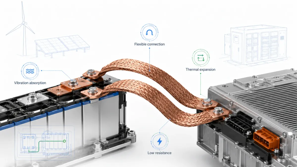
Design examples for different new energy applications
A passenger EV battery module may use thin laminated flexible copper busbars with film or epoxy insulation. The design priority is compact routing, low terminal stress, controlled high-voltage insulation and repeatable automated assembly. The busbar may need selective plating at contact pads and precisely masked insulation around holes.
A commercial vehicle battery pack may use thicker rigid copper busbars for pack-level connections and braided copper grounding links for vibration. The design priority is durability, service access, high peak current and strong bolted joints. Insulation may be epoxy coating, heat shrink or molded covers depending on service requirements.
A utility BESS rack may use tinned rigid copper busbars for cabinet-level distribution and flexible laminated links between modules. The design priority is long service life, corrosion resistance, safe maintenance and consistent performance under repeated cycling. The busbar drawing should define plating, contact mask areas, insulation color and dielectric test requirements.
A fast charging cabinet may use formed copper busbars between contactors, fuses, power modules and output terminals. The design priority is thermal management, compact layout, low inductance and safe service barriers. Laminated or paired busbars may be used to keep positive and negative paths close together.
A data center backup power module may use custom busbars for battery strings, UPS connections and high-current distribution. The design priority is reliability, low voltage drop, clean cabinet routing and fast installation. JUMAI’s article on bus bars for server rack power distribution is useful for teams working at the intersection of battery backup and high-density power infrastructure.
Common mistakes to avoid
The most common battery busbar mistakes are usually simple, but they create expensive consequences.
The first mistake is treating ampacity as a catalog number. A busbar’s current rating depends on temperature rise, cooling, enclosure, insulation, duty cycle and contact resistance. A value copied from another design may not apply.
The second mistake is ignoring movement. Battery cells swell, racks vibrate, vehicles experience shock and copper expands with temperature. A rigid busbar may be correct in a static CAD model but wrong in a moving system.
The third mistake is placing insulation too late in the design process. Coating thickness, mask lines, edge radius and creepage distance must be considered before final geometry. Insulation cannot simply be “added at the end” without affecting fit and contact quality.
The fourth mistake is under-specifying contact areas. Holes, slots, plating, flatness, burr direction and torque assumptions need to be controlled. Many hot spots begin at the joint, not in the middle of the copper path.
The fifth mistake is choosing the lowest initial part price without considering assembly. A cheaper busbar may require more labor, create rework, need extra covers or increase warranty risk. A custom busbar should be evaluated by total system cost.
The sixth mistake is waiting too long to involve the manufacturer. If the busbar supplier sees the design only after the pack is frozen, there may be no room to improve bend radius, terminal geometry, coating mask or assembly access. Early DFM review is faster and cheaper.
Why work with JUMAI for custom battery bus bars?
JUMAI is positioned for custom projects where the busbar must be tailored to a specific battery module, pack, cabinet or power device. The company’s copper busbar range includes hard or rigid copper busbars, soft copper busbars, braided copper busbars, laminated flexible copper busbars, tinned copper busbars and insulated busbars. The service page for Custom Copper Busbars describes high-purity T2/C11000 copper, 99.9% copper purity, ISO 9001 quality system, rigid busbars for structural current paths, braided busbars for vibration, laminated flexible busbars for tight spaces, tin/nickel/silver plating and insulation options.
The advantage is not only that JUMAI can cut copper. It is that JUMAI can review conductor geometry, bending, punching, terminal pressing, diffusion welding, plating, insulation and inspection together. For battery buyers, this combined view is valuable because the final component must work electrically, mechanically and commercially. A busbar is not successful until it can be assembled repeatedly, pass testing and perform reliably in the finished system.
JUMAI also supports related deep-drawn components, stamping dies and tooling components. This matters when a project needs more than a conductor. A battery pack may require a copper busbar, a stamped sensing part, a protective cover, a deep-drawn metal feature, a bracket or a custom terminal accessory. Reviewing these parts together can reduce interference, simplify assembly and shorten development cycles.
For engineering teams comparing options, the best starting point is to share drawings and operating requirements. If the current path is stable, JUMAI may recommend a rigid copper busbar. If the path must absorb movement, a laminated flexible or braided busbar may be better. If the voltage is high and space is compact, an insulated busbar with controlled mask zones may be required. If production volume is high, tooling and process optimization can reduce unit cost.
Practical ordering workflow
A professional battery busbar project usually moves through six stages.
First, the buyer provides the application requirements, drawings and expected electrical load. The supplier checks whether the geometry is reasonable for copper thickness, bend radius, hole position, contact area and insulation.
Second, the supplier provides design-for-manufacturing feedback. This may include changing a bend radius, adding edge radius, modifying a hole slot, extending a flexible section, selecting a plating, changing insulation or adjusting tolerances.
Third, prototypes are produced for fit, assembly and electrical checks. At this stage, the buyer should install the part in the real module or cabinet and test torque access, clearance, insulation fit and any movement.
Fourth, electrical and thermal validation is performed. The team checks resistance, voltage drop, temperature rise, dielectric withstand and behavior under the expected duty cycle.
Fifth, the production drawing and quality plan are frozen. Critical dimensions, test requirements, finish specifications, packaging and traceability are defined.
Sixth, mass production begins with incoming material control, process inspection, final inspection and packaging. For repeat orders, stable tooling and clear quality criteria help reduce lead time and variation.
This workflow may sound formal, but it prevents common problems. Custom busbars are often low-cost compared with the full battery system, yet they can stop assembly if they are wrong. Spending time on early review protects launch schedules.
FAQ: battery bus bars for new energy applications
Are copper battery bus bars better than aluminum bus bars?
Copper is usually better when the design needs compact size, low resistance, high thermal spreading and reliable contact in a limited space. Aluminum can be attractive for weight and cost, especially in larger structures, but it generally needs more cross-section for the same resistance and requires careful joint design. The best choice depends on current, weight target, contact materials, corrosion environment and manufacturing process.
When should I choose a flexible battery busbar?
Choose a flexible battery busbar when the connection must absorb vibration, thermal expansion, cell swelling, installation tolerance or movement. Laminated flexible copper busbars are well suited for compact battery module links. Braided copper busbars are useful for vibration isolation, grounding and multi-directional movement.
Can a flexible busbar carry the same current as a rigid busbar?
Yes, if it is designed with sufficient copper cross-section, good terminal bonding and appropriate insulation. The current rating still depends on temperature rise, cooling, duty cycle and contact resistance. Flexible construction adds variables such as foil count, braid density, terminal compression and bend behavior, so these should be specified clearly.
What insulation is best for high-voltage battery bus bars?
There is no single best insulation for every project. Heat shrink is practical for simple shapes and prototypes. Epoxy powder coating is strong for many rigid and laminated busbars. Film insulation such as PET, PI or PA12 can be useful in compact high-voltage layouts. Silicone or TPE can support flexible links. The right choice depends on voltage, creepage/clearance, temperature, abrasion, flame rating, coating thickness and assembly method.
Should battery busbars be plated?
Many battery busbars use plating at contact zones. Tin plating is common for corrosion resistance and practical contact performance. Nickel plating is useful for harsher environments or higher temperature exposure. Silver plating can be selected for demanding high-current contact performance. Bare copper may be acceptable in some welded or protected areas. Selective plating is often the best solution.
What information is needed to calculate busbar size?
At minimum, provide continuous current, peak current, pulse duration, voltage, allowable temperature rise, ambient temperature, insulation type, cooling condition, current path length and contact design. For a reliable result, include the real enclosure and assembly condition because airflow and neighboring heat sources can change performance significantly.
Do battery bus bars need dielectric testing?
Insulated busbars for high-voltage systems commonly require dielectric withstand or hi-pot testing according to the customer specification or product safety plan. The test voltage, duration and acceptance criteria should be defined before production. Pinholes, thin coating areas and damaged insulation edges should be controlled.
What is the difference between laminated flexible and braided busbars?
A laminated flexible busbar uses stacked copper foils joined at terminals, with the middle section free to flex. It offers compact, controlled bending and good contact geometry. A braided busbar uses woven fine copper wires and offers excellent multi-directional flexibility and vibration absorption. Laminated busbars are often better for compact module links; braided busbars are often better for grounding and vibration isolation.
Can JUMAI make busbars from my CAD drawings?
Yes. JUMAI can review 2D drawings and 3D CAD files for custom copper busbars, including rigid, flexible, braided and insulated designs. The best RFQ package includes STEP or IGES files, PDF drawings, current and voltage requirements, insulation requirements, plating requirements, expected volume and quality documentation needs.
How early should a busbar supplier join the battery design process?
As early as possible after the current path and mechanical envelope are roughly known. Early supplier review can prevent impossible bend radii, poor hole positions, coating mask problems, insufficient flex length and assembly access issues. This is much cheaper than correcting the busbar after pack tooling or enclosure design is frozen.
Final thoughts
Battery bus bars are small compared with a complete EV pack, BESS cabinet or charging system, but they carry the current that makes the product useful. Their performance affects efficiency, heat, safety, reliability, assembly speed and service life. That is why battery busbar design should combine electrical calculation, mechanical review, insulation coordination, surface finishing and manufacturing planning.
For many new energy applications, copper remains the most practical conductor because it provides high conductivity, compact cross-section and strong thermal behavior. Rigid copper busbars are ideal for stable, high-current routes. Laminated flexible copper busbars solve tight-space and movement problems. Braided copper busbars absorb vibration and misalignment. Insulated busbars provide the safety layer needed for compact high-voltage products. The best design may combine all of these options in one system.
JUMAI supports global customers with custom copper busbars for EV batteries, energy storage systems, charging equipment, data centers, renewable power and industrial electrification. If your project needs a rigid copper busbar, flexible copper busbar, braided copper busbar, insulated busbar or a hybrid current path with custom metal accessories, JUMAI can review your drawings and help turn the requirement into a manufacturable part. Start with the Custom Copper Busbars service page, compare related technical articles such as the battery busbar design guide and flexible busbar for EV battery modules, then prepare your CAD files, current profile plus insulation requirements for a focused engineering discussion.