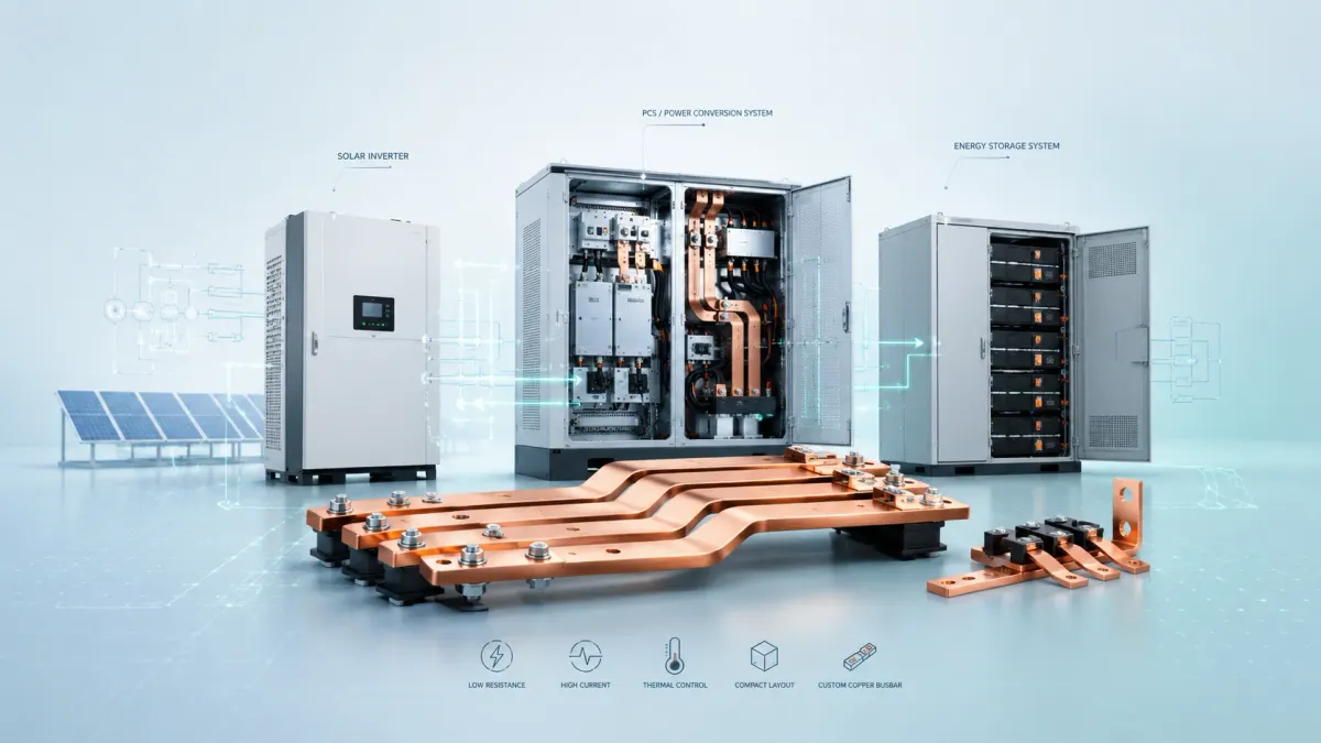
A DC bus bar looks simple from the outside. It may be a flat copper strip, a laminated flexible conductor, a plated terminal bar, or a compact assembly hidden inside a solar inverter or power conversion system cabinet. In real equipment, however, the DC bus bar is one of the most important parts of the power path. It carries high current, controls voltage drop, transfers heat, supports mechanical assembly, and helps the electrical design remain stable during long service life.
This is especially true in solar inverters, PCS cabinets and energy storage systems. These products are no longer low-current auxiliary devices. Modern renewable energy equipment must handle hundreds of amperes, and larger systems may divide thousands of amperes across multiple power modules, DC switches, fuses, contactors, battery racks and inverter bridges. As solar power and battery storage become mainstream infrastructure, the copper busbar inside the cabinet becomes a business-critical detail. A poor busbar design can create hot spots, difficult assembly, unpredictable maintenance, insulation risk, vibration problems and unnecessary copper cost. A well-designed DC bus bar can make the same cabinet cleaner, safer, easier to assemble and more competitive.
The market direction makes this more important. According to the International Renewable Energy Agency Renewable Capacity Highlights 2026, global renewable power capacity reached 5,149 GW by the end of 2025, and 692 GW was added in that single year. Solar power accounted for the largest share of additions. At the same time, the IEA Batteries and Secure Energy Transitions report describes battery storage in the power sector as the fastest growing commercially available energy technology in 2023. More solar, more storage and more power electronics mean more DC cabinets, more DC connection points and more demand for reliable busbar design.
For buyers, engineers and project managers, the goal is not simply to buy a piece of copper. The goal is to specify a conductor architecture that matches the real operating conditions of the equipment. A solar inverter DC input bus may need compact routing and low inductance. A PCS cabinet may need repeated module assembly, insulation coordination and service-friendly connection points. A battery energy storage cabinet may need flexible connections that absorb tolerance, thermal expansion and vibration. For these situations, JUMAI manufactures custom copper busbars, including rigid copper busbars, laminated flexible copper busbars and braided copper busbars, with punching, bending, plating and insulation options. You can review the company capabilities on the JUMAI custom copper busbars page, and related internal references such as the flexible copper busbar guide and copper bus bars for power distribution guide.
This article explains DC bus bar design in practical language for solar inverters, PCS cabinets and energy storage systems. It is written for design engineers, sourcing teams, inverter manufacturers, energy storage integrators, panel builders and OEM project teams that need a custom busbar supplier rather than a generic catalog part.
- What is a DC bus bar?
- Where DC bus bars are used in solar inverters, PCS cabinets and ESS
- Market and system trends that affect DC bus bar design
- Key electrical calculations: current, voltage drop and heat
- Selecting the right DC bus bar architecture
- Selecting the right DC bus bar architecture
- DC bus bar material: why copper still dominates high-current designs
- Insulation, creepage and clearance in high-voltage DC systems
- Thermal management and temperature rise
- Mechanical design: tolerance, vibration and installation sequence
- Low inductance and DC link layout
- Surface treatment and contact reliability
- Practical design data for RFQ and engineering review
- Common design mistakes in DC bus bars
- Design approach by application
- Manufacturing process considerations
- Quality inspection and testing
- Cost optimization without weakening reliability
- How JUMAI supports custom DC bus bar projects
- Example design workflow for a DC bus bar project
- Frequently asked questions
- Design the DC bus bar as part of the whole power system
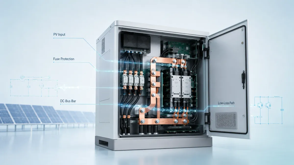
What is a DC bus bar?
A DC bus bar is a solid or assembled conductor used to distribute direct current between electrical devices. In a renewable energy system, it may connect PV strings to a DC disconnect, fuses to the inverter input, battery racks to a DC combiner, contactors to a power conversion module, or capacitors to semiconductor power modules. The term can refer to a single copper bar, a pair of positive and negative conductors, a laminated DC link assembly, or a customized busbar set with insulation, plated contact areas and formed mounting points.
The key difference between a DC bus bar and a wire harness is geometry. A cable is round, flexible and routed through space. A busbar is usually flat or formed into a defined shape. Because its geometry is controlled, the busbar can offer predictable assembly, compact packaging, lower voltage drop for a given path, better heat dissipation and easier connection to flat terminals. In high-current equipment, these advantages can matter more than the material cost difference between cable and copper strip.
A DC bus bar is also different from an AC distribution busbar in its design priorities. In a pure DC path, steady-state skin effect is not the main concern. However, solar inverters and PCS cabinets are power electronic systems. They include switching devices, capacitors, DC link ripple, fault transients and electromagnetic compatibility requirements. For this reason, the physical layout of positive and negative conductors, loop area, insulation thickness, terminal pressure and thermal path all influence system reliability. A flat copper bar that passes a basic resistance calculation may still be unsuitable if it creates an excessive current loop, a difficult creepage path or a mechanical stress point near a contactor.
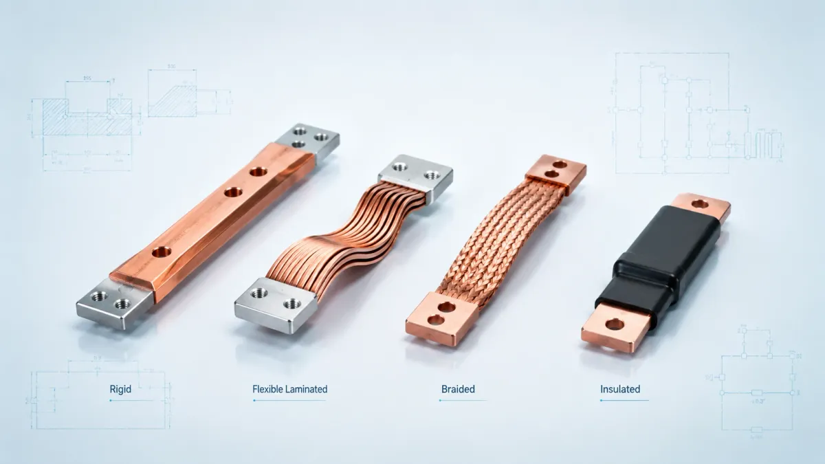
For JUMAI projects, the term DC bus bar may include several product structures:
- A rigid copper busbar for stable, fixed connection points.
- A laminated flexible copper busbar for tight routing and controlled bending.
- A braided copper busbar for grounding, movement zones and vibration-sensitive connections.
- A plated and insulated copper busbar assembly for safe high-current cabinets.
- A punched, bent or formed busbar customized to customer drawings.
The right structure depends on the electrical current, voltage, temperature, assembly direction, vibration level, available space and maintenance plan.
Where DC bus bars are used in solar inverters, PCS cabinets and ESS
In a solar inverter, the DC bus bar is usually found on the PV input side, the DC link section, the connection between DC disconnect devices and power modules, and the capacitor or semiconductor interface. Utility-scale and commercial inverters often operate with high DC voltage to reduce current and cable losses. For example, 1,000 Vdc and 1,500 Vdc architectures are common in utility-scale PV projects, and NREL cost benchmark work has used a 1,500 Vdc tracking utility-scale PV system as a baseline model in cost analysis. The higher the voltage, the more careful the insulation, creepage, clearance and switching transient design must be.
In a PCS cabinet, the DC bus bar connects the battery side to DC switches, fuses, contactors, pre-charge circuits, DC link capacitors and inverter power modules. PCS equipment is a bridge between battery energy storage and the AC grid. It must support charging and discharging, fault isolation, thermal management and serviceability. The busbar must therefore work with the cabinet layout, not just with an ampacity table. It needs to match the real connection sequence inside the cabinet.
In a battery energy storage system, the DC bus bar may appear at rack level, cabinet level, container level and PCS interface level. Battery racks often need compact, insulated and repeatable connections. The PCS interface may require higher current and more rigid support. Between battery modules, flexible copper conductors may be used to absorb stack-up tolerance and thermal expansion. JUMAI discusses this design logic in the battery busbar design guide for EV battery packs and BESS cabinets and in the flexible busbar design guide for high-vibration power systems.
A practical system may use all three busbar forms. A rigid bar handles the main stable route. A laminated flexible busbar handles a tight bend or small displacement. A braided copper connector handles grounding, bonding or a part of the system exposed to vibration. The best design is not always the most flexible or the thickest. It is the design that places rigidity and flexibility where each provides value.
Market and system trends that affect DC bus bar design
The growth of solar and storage is not only increasing production volume. It is changing the electrical and mechanical expectations placed on conductors. Larger inverter blocks, more integrated ESS containers, modular PCS designs and high-voltage battery racks all push busbar design toward higher current density and higher assembly precision.
First, solar and storage systems are becoming more modular. A manufacturer may build PCS cabinets from repeated power modules. A BESS integrator may connect multiple battery racks in parallel. A solar inverter manufacturer may use common copper parts across several power ratings. In this environment, a custom DC bus bar should be easy to install repeatedly with low operator variation. Hole accuracy, bend angle, flatness and terminal finish all become production quality issues.
Second, cabinet space is becoming more valuable. Many OEMs want higher power density without increasing cabinet footprint. This creates a need for busbars that can route current through tight spaces while keeping safe insulation distances. Laminated flexible busbars can be useful in this situation because they combine copper conductivity with controlled bendability. The JUMAI article what makes flexible conductors useful in compact power systems explains how flexible busbars can reduce cable lugs, clamps and routing uncertainty.
Third, higher DC voltage reduces current for the same power, but it increases the importance of insulation coordination. At 1,500 Vdc, a small design mistake around a sharp edge, burr, coating defect or insufficient clearance can become a reliability risk. This does not mean every busbar must be overbuilt. It means the busbar drawing should define the voltage level, pollution degree expectation, insulation material, edge radius, coating coverage, uninsulated contact area and test requirements.
Fourth, renewable energy systems are often installed in harsh environments. Solar farms and containerized ESS installations can experience high ambient temperature, humidity, dust, salt spray, transportation vibration and long periods of high load. The busbar should therefore be designed as part of a thermal and environmental system. Copper thickness alone is not enough. Surface treatment, contact area, bolt pressure, insulation material, cabinet airflow and maintenance access all affect long-term performance.
Key electrical calculations: current, voltage drop and heat
The first step in DC bus bar design is to estimate current. For a simplified DC calculation, current is power divided by voltage:
I = P / V
This formula gives a starting point only. Real design must also consider overload, derating, temperature, parallel paths, ripple current, fault current and standards required by the final product. Still, the formula helps buyers and engineers understand why system voltage matters. If a 1 MW power path operates at 1,000 Vdc, the ideal DC current is about 1,000 A. At 1,500 Vdc, the current is about 667 A. That difference changes conductor cross-section, terminal size, thermal loss and cabinet layout.
Table 1. Approximate DC current at common power and voltage levels
| Power path rating | Current at 800 Vdc | Current at 1,000 Vdc | Current at 1,500 Vdc | Design note |
|---|---|---|---|---|
| 250 kW | 313 A | 250 A | 167 A | Common sub-module or smaller PCS path. |
| 500 kW | 625 A | 500 A | 333 A | Needs careful terminal and thermal design. |
| 1 MW | 1,250 A | 1,000 A | 667 A | Often divided into parallel modules or bus sections. |
| 2 MW | 2,500 A | 2,000 A | 1,333 A | Usually requires a complete busbar system review. |
| 5 MW | 6,250 A | 5,000 A | 3,333 A | Typically split across multiple cabinets, modules or parallel conductors. |
After current is known, the next question is voltage drop. Voltage drop is the lost voltage across the conductor and connection points. In a DC conductor, it can be estimated as:
Vdrop = I x R
The power loss becomes:
Ploss = I^2 x R
This is why high current is unforgiving. If current doubles, the heat generated by the same resistance increases by four times. A small contact resistance that looks harmless in a low-current prototype may create a severe hot spot in a 1,000 A cabinet. For this reason, DC bus bar design must include the conductor body and the joints. The overlap area, plating, flatness, tightening torque, washer selection and contact pressure can be as important as the copper cross-section.
Copper is preferred for many high-current busbars because it combines high electrical conductivity, good thermal conductivity and good formability. The Copper Development Association busbar information notes ampacity tables for rectangular Copper No. 110 busbars calculated using nominal conductivity of 99% IACS. The Copper Alliance copper attributes page also notes that pure copper has the best electrical and thermal conductivity of any commercial metal. JUMAI commonly works with high-conductivity copper for custom busbars, and the JUMAI copper material guide explains why copper remains a preferred material in high-current conductors.
The busbar manufacturer should not treat ampacity as a fixed number printed in a universal table. Ampacity changes with ambient temperature, temperature rise limit, air movement, conductor orientation, plating, enclosure ventilation, spacing from other hot parts and heat conduction into terminals. A wide, thin copper bar may dissipate heat differently from a narrow, thick bar with the same cross-section. A busbar inside a sealed outdoor cabinet behaves differently from one in an open, ventilated assembly. Therefore, a reliable RFQ should include current, duty cycle, ambient temperature, enclosure type, expected temperature rise limit and whether the busbar will be insulated.
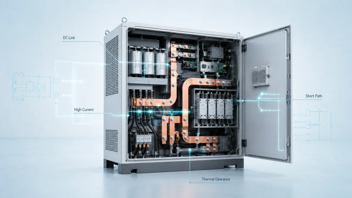
Selecting the right DC bus bar architecture
The busbar structure should match the mechanical reality of the cabinet. Many failures begin when the conductor is electrically sized but mechanically wrong. A rigid copper bar is strong and compact, but it should not be forced to absorb movement between parts that shift during transport or thermal cycling. A braided copper connector is excellent for movement and bonding, but it is not always the best choice for a controlled low-inductance DC link. A laminated flexible busbar can solve tight routing and small movement, but it needs correct terminal welding, insulation and bend radius.
Selecting the right DC bus bar architecture
The busbar structure should match the mechanical reality of the cabinet. Many failures begin when the conductor is electrically sized but mechanically wrong. A rigid copper bar is strong and compact, but it should not be forced to absorb movement between parts that shift during transport or thermal cycling. A braided copper connector is excellent for movement and bonding, but it is not always the best choice for a controlled low-inductance DC link. A laminated flexible busbar can solve tight routing and small movement, but it needs correct terminal welding, insulation and bend radius.
Table 2. DC bus bar architecture options for solar, PCS and ESS applications
| Busbar type | Best-fit use case | Main advantage | Design cautions | Typical JUMAI customization |
|---|---|---|---|---|
| Rigid copper busbar | Fixed DC routes, DC switch to fuse, fuse to contactor, cabinet main bus | High mechanical strength, predictable geometry, easy bolted assembly | Cannot absorb large misalignment; bend and hole tolerances must be controlled | CNC bending, punching, plating, insulation, edge finishing |
| Laminated flexible copper busbar | Tight cabinet routing, module connection, battery rack to PCS interface, tolerance compensation | Combines high conductivity with controlled flexibility and space saving | Must define terminal welding, insulation coverage, bend zone and bend radius | Multilayer copper foil, press-welded ends, custom insulation, plated terminals |
| Braided copper busbar | Grounding, bonding, vibration zones, moving or tolerance-sensitive interfaces | Excellent flexibility and vibration absorption | Higher geometry variability; may need sleeve or insulation for protection | Bare or tinned braid, cold-pressed terminals, custom hole pattern |
| Insulated DC busbar set | High-voltage solar inverter, PCS cabinet, ESS cabinet | Reduces accidental contact and phase-to-phase or polarity short risk | Insulation edge, coating thickness, dielectric test and exposed contact area must be specified | PVC, epoxy, heat-shrink or customer-specified insulation, masked contact areas |
| Hybrid busbar assembly | Cabinets using rigid main bus plus flexible links | Balances compact routing, strength and tolerance absorption | Requires early layout review to avoid interference and service issues | Combined rigid, laminated flexible and braided parts supplied as a matched set |
For solar inverters, laminated structures are often attractive where the positive and negative conductors should be kept close to reduce loop inductance. For a DC link near capacitors and semiconductor modules, a laminated busbar can provide a compact current path and help control switching behavior. For a DC input path from a fuse or switch, a rigid bar may be simpler and more cost-effective. For grounding, vibration isolation or cabinet-door bonding, braided copper may be the right choice.
For PCS cabinets, the busbar design should follow the module service strategy. If power modules are removed from the front, the busbar should not block access. If contactors and fuses are replaced during maintenance, the busbar should provide enough tool clearance. If current is split across parallel modules, the connection geometry should help balance current instead of forcing one branch to carry more heat. JUMAI’s power bus bar applications article gives a useful internal overview of how different busbar structures fit switchgear, battery systems and other power distribution applications.
For energy storage cabinets, the busbar must often balance electrical safety and field serviceability. Battery racks can have many connection points, and each connection point creates a potential heat source. A busbar that is easy to install, easy to inspect and difficult to misassemble can reduce commissioning risk. Insulation color, polarity marking, hole pattern uniqueness and terminal orientation can all help prevent field errors.
DC bus bar material: why copper still dominates high-current designs
Copper is not the only possible busbar material, but it remains the default choice in many high-current renewable energy applications. The reason is not only conductivity. Copper also has good thermal conductivity, good fatigue performance for many conductor structures, strong joint performance when properly plated and tightened, and excellent manufacturability for punching, bending, welding, brazing, plating and insulation.
Aluminum is sometimes used when weight and cost are the highest priorities. It can be a valid material in certain distribution assemblies. However, aluminum requires a larger cross-section for the same resistance, has different oxide behavior at joints, and needs careful transition design when connected to copper terminals. In compact PCS cabinets and inverter modules, the space penalty and joint complexity can reduce the apparent cost advantage. For many custom DC bus bar projects, copper gives a better balance of electrical performance, compact size and manufacturing reliability.
The material grade should be defined in the drawing or technical agreement. Common choices include C11000 or T2 high-conductivity copper, depending on the regional material designation and procurement standard. The required conductivity, hardness state, thickness tolerance and surface finish should be stated. For flexible laminated busbars, the copper foil thickness and number of layers are also important. JUMAI’s product page states that the company manufactures custom copper busbars using high-purity T2/C11000 copper, and offers rigid, braided and laminated flexible categories for different applications.
Plating should be selected for the contact environment, not only for appearance. Tin plating is widely used because it helps protect copper against oxidation and supports stable bolted contacts in many industrial environments. Nickel plating may be selected where higher temperature or corrosion resistance is required. Silver plating can be used for high-performance contacts, but cost must be justified by the application. In many projects, only the contact areas need plating while the rest of the bar is insulated or protected. The drawing should clearly show plated zones, masked zones and acceptable surface condition.
Edge quality matters. A sharp copper edge can damage insulation, concentrate electric field, cut into heat-shrink tubing or injure assembly workers. Burrs around punched holes can also reduce contact quality. For high-voltage DC busbars, edge radius and deburring should be treated as functional features. The higher the voltage and the tighter the cabinet, the more important this becomes.
Insulation, creepage and clearance in high-voltage DC systems
A DC bus bar does not only carry current. It also separates energy. In a solar inverter or ESS cabinet, the positive and negative poles may sit close to each other, and both may be close to grounded metal. Insulation design must therefore be considered from the beginning.
Important insulation questions include:
- What is the maximum operating voltage and maximum transient voltage?
- Is the system 600 Vdc, 1,000 Vdc, 1,500 Vdc or another value?
- What pollution degree and installation environment are expected?
- Is the busbar inside a sealed cabinet, ventilated cabinet, outdoor enclosure or container?
- What insulation material is required by the customer or certification plan?
- Which areas must remain exposed for bolted, welded or press-fit contact?
- What dielectric test should the finished busbar or assembly pass?
Solar power conversion equipment is often evaluated under standards such as IEC 62109, which defines safety requirements for power converters used in photovoltaic systems, and UL 1741, which covers inverters, converters, charge controllers and interconnection system equipment for distributed energy resources. Energy storage projects may also refer to the IEC 62933 series, UL 9540 and related safety evaluation methods such as UL 9540A. A busbar supplier does not certify the full inverter or ESS system by itself, but it should understand that the copper part must support the product’s certification pathway.
Insulation materials may include PVC dip coating, epoxy coating, powder coating, heat-shrink tubing, molded covers or customer-specified sleeves. Each has advantages and limitations. Dip coating can cover complex shapes but must be controlled around edges and holes. Epoxy coating offers strong dielectric protection but may require strict thickness and adhesion control. Heat-shrink tubing is flexible and practical for some shapes, but it may not cover complex terminals as cleanly. A separate plastic cover can improve service safety, but it adds assembly parts and space.
For DC busbars, creepage and clearance are not optional layout details. Clearance is the shortest air distance between conductive parts. Creepage is the shortest path along an insulating surface. Both depend on voltage, environment and standards. Engineers should avoid placing exposed positive and negative contact areas too close together, especially near screw heads, washers, cabinet edges or service tools. If a busbar must be compact, insulation shape and barrier design should be considered early.
Thermal management and temperature rise
Temperature rise is one of the most visible signs of busbar performance. A DC bus bar may pass current, but if it runs too hot, it can age insulation, loosen joints, increase resistance, affect nearby components and reduce system reliability. In outdoor renewable energy cabinets, ambient temperature can already be high before load current is applied. This leaves less thermal margin.
The heat in a busbar comes mainly from conductor resistance and contact resistance. Conductor heat depends on current, length, cross-section and material conductivity. Contact heat depends on contact area, surface condition, plating, flatness, bolt pressure and contamination. A busbar with a large copper cross-section can still overheat if the joint is poor.
Thermal design should include the following details:
- Current and overload profile.
- Maximum ambient temperature inside the cabinet, not only outside the cabinet.
- Acceptable temperature rise at the conductor body.
- Acceptable temperature at insulation and contact areas.
- Airflow direction and obstructions.
- Distance from heat-generating components such as IGBTs, SiC modules, fuses and contactors.
- Whether the busbar is vertical or horizontal.
- Whether multiple conductors are closely packed.
- Whether the busbar is bare, plated, painted or fully insulated.
A useful design habit is to separate the busbar into thermal zones. The middle conductor zone is controlled mostly by cross-section and surface heat dissipation. The joint zone is controlled mostly by contact quality. The bend zone is controlled by mechanical forming and local current density. The insulation zone is controlled by coating material and thickness. Each zone can fail for a different reason.
Thermal simulation can help, but it should be supported by prototype testing. Infrared camera inspection during current loading is useful for finding hot spots. Temperature sensors at terminals can verify whether contact resistance is acceptable. For production, torque control and surface cleanliness are just as important as the original design.
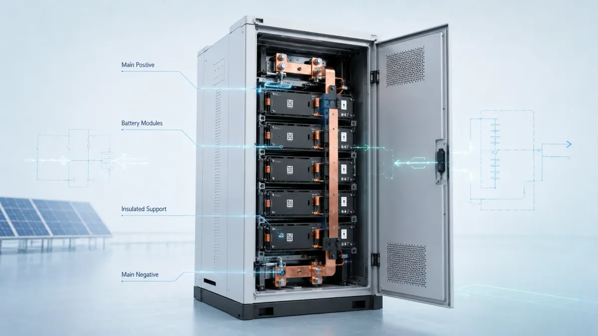
Mechanical design: tolerance, vibration and installation sequence
A copper busbar is a mechanical part as well as an electrical part. In solar inverters, PCS cabinets and ESS systems, mechanical problems often appear during assembly rather than during CAD design. Holes may not align perfectly. A contactor terminal may sit slightly higher than expected. A battery rack may shift during transport. A cabinet wall may flex. A rigid busbar can transfer these errors directly into the terminal, creating stress and loosening risk.
This is why mechanical tolerance analysis should be part of busbar design. If two connection points are fixed on the same machined bracket, a rigid copper bar may be ideal. If two connection points are mounted on different modules, frames or replaceable assemblies, a flexible section may be safer. A laminated flexible busbar can absorb small misalignment while still providing a defined power path. A braided copper busbar can absorb larger movement or vibration, especially for grounding and bonding.
The installation sequence should be reviewed before the drawing is released. Ask simple questions:
- Can the operator insert the busbar without bending it beyond its design limit?
- Can all bolts be accessed with standard tools?
- Can the busbar be installed after other components are already in place?
- Is there enough clearance for washers and torque tools?
- Are positive and negative parts clearly different to prevent wrong installation?
- Will the busbar interfere with cables, sensors, fiber optics, cooling hoses or cabinet doors?
- Can a service technician replace a fuse, contactor or module without removing too many unrelated parts?
For high-volume equipment, these questions affect labor cost and warranty risk. A custom busbar may appear more expensive than a generic copper strip, but if it reduces assembly time, reduces error rate and improves service access, the total cost of ownership can be lower.
Vibration should not be ignored. PCS cabinets and BESS containers may experience transportation vibration before installation. Some equipment is placed near transformers, cooling fans or industrial loads. A rigid busbar with a long unsupported span can vibrate. A heavy cable pulling on a terminal can create stress. Flexible copper parts can help, but they should be designed with controlled bend zones and adequate support. For high-vibration environments, JUMAI’s experience with flexible and braided busbars is relevant because these structures are designed to absorb movement that a rigid bar cannot.
Low inductance and DC link layout
In power electronics, resistance is not the only electrical parameter. Inductance also matters, especially near the DC link of solar inverters and PCS modules. When switching devices turn on and off quickly, stray inductance can create voltage overshoot, ringing and electromagnetic interference. Silicon carbide devices can switch faster than older devices, which makes layout even more important.
A low-inductance DC busbar usually keeps the positive and negative current paths close together and arranged so that their magnetic fields partially cancel. This is why laminated busbar structures are common in compact DC link assemblies. A simple pair of separated copper bars may carry the required current, but it can create a larger loop area. A laminated structure with insulation between conductors can reduce loop area while keeping the assembly compact.
Not every DC busbar needs to be a laminated low-inductance structure. A connection from a DC switch to a fuse may prioritize ampacity, clearance and service access. A DC link between capacitors and power modules may prioritize low inductance and symmetrical current distribution. The design should identify which parts of the current path are sensitive to switching performance and which parts are mainly distribution paths.
For DC link busbars, designers should pay attention to:
- Symmetrical current paths to parallel power modules.
- Short distance between DC capacitors and switching devices.
- Close coupling of positive and negative conductors.
- Smooth transitions with no unnecessary loop area.
- Adequate insulation between laminated layers.
- Control of partial discharge or dielectric stress at high voltage.
- Reliable terminal pressure and flatness.
A custom supplier should be involved early for these parts because manufacturing constraints influence electrical performance. Layer thickness, insulation material, hole position, exposed contact zones, welding area and bending sequence all affect the final result.
Surface treatment and contact reliability
The joint is often the weakest part of a high-current busbar system. Copper has excellent conductivity, but exposed copper can oxidize. Oxide, contamination, insufficient pressure or poor flatness can increase contact resistance. In DC systems, this can create heat, and heat can further accelerate contact degradation.
Surface treatment is therefore a functional decision. Tin plating is common for many industrial busbar contacts. It provides oxidation protection and stable performance in bolted joints when used correctly. Nickel plating can be useful where temperature, corrosion or wear requirements are higher. Silver plating is used in selected high-performance contacts where low contact resistance and high conductivity justify the cost.
Contact design should specify:
- Plating material and thickness.
- Whether plating is full-body or selective.
- Contact overlap area.
- Bolt size, grade and tightening torque.
- Washer type.
- Surface flatness.
- Maximum burr height.
- Whether conductive grease or other surface treatment is permitted.
- Inspection criteria for scratches, stains and discoloration.
For production, torque control is essential. A well-designed busbar can still fail if bolts are under-tightened, over-tightened or tightened in the wrong sequence. If the contact surface is large, multiple bolts may be required. If multiple bolts are used, tightening sequence can affect pressure distribution. For field maintenance, the documentation should define whether bolts must be re-torqued after transport or after thermal cycling.
Practical design data for RFQ and engineering review
A custom DC bus bar RFQ should contain enough data for the supplier to review manufacturability and risk. If the buyer only sends a rough outline and asks for a price, the quotation may be fast but incomplete. The supplier may not know the voltage, current, insulation requirement or contact environment. This increases redesign risk later.
Table 3. Recommended information to provide when requesting a custom DC bus bar quote
| RFQ item | Why it matters | Recommended detail |
|---|---|---|
| Rated current and overload profile | Determines conductor cross-section and temperature rise | Continuous current, peak current, duration, duty cycle |
| DC voltage level | Drives insulation, creepage and clearance decisions | Nominal voltage, maximum voltage, transient expectation |
| Application location | Changes mechanical and thermal priorities | Solar inverter, PCS cabinet, BESS rack, DC combiner, contactor link |
| Available space | Determines whether rigid, flexible or laminated design is practical | STEP file, 2D drawing, bend envelope, keep-out zones |
| Connection points | Controls hole pattern and contact design | Hole size, slot direction, terminal thickness, bolt grade, torque |
| Material requirement | Affects conductivity and forming behavior | C11000/T2 copper, thickness tolerance, hardness state |
| Surface finish | Controls oxidation and contact resistance | Bare copper, tin plating, nickel plating, silver plating, selective plating |
| Insulation requirement | Supports product safety and service protection | Material, color, thickness, dielectric test, exposed contact zones |
| Environment | Affects corrosion, heat and vibration design | Indoor/outdoor, humidity, salt spray, altitude, ambient temperature |
| Production volume | Influences tooling and process choice | Prototype quantity, pilot batch, annual volume, packaging requirement |
| Compliance pathway | Helps align with system certification | IEC 62109, UL 1741, IEC 62933, UL 9540, customer-specific tests |
JUMAI can support early design review when customers provide CAD drawings, electrical requirements and application conditions. For complex parts, it is useful to share both the busbar drawing and the surrounding cabinet layout. This helps identify whether a bend is manufacturable, whether a hole is too close to an edge, whether insulation can be applied cleanly, and whether a flexible segment is needed.
Common design mistakes in DC bus bars
One common mistake is choosing copper thickness only by current. Current is important, but the busbar also needs proper width, surface area, thermal path, contact area and mechanical support. A thick but narrow bar may be difficult to bend, may create poor heat dissipation and may not fit the terminal. A wider and thinner bar can sometimes perform better in a cabinet, depending on airflow and layout.
Another mistake is ignoring contact resistance. Engineers may calculate the resistance of the copper body but forget the bolted joint. In high-current DC systems, the joint can become the hottest point. Poor plating, burrs, insufficient overlap, wrong washers or low torque can turn a good copper bar into a failure point.
A third mistake is placing a rigid bar between parts that move. Battery racks, contactors, cabinet frames and power modules can have tolerance differences. If a rigid bar is forced into place, it may bend slightly during assembly and store stress. Over time, thermal cycling and vibration can loosen the joint or crack the terminal. Flexible laminated or braided conductors should be considered when movement is expected.
A fourth mistake is treating insulation as decoration. Insulation must be designed around voltage, edge radius, coverage, thickness, adhesion and exposed contact zones. If a coating is too close to the contact area, it may creep under the washer and reduce contact pressure. If the uncoated area is too large, it may reduce safety distance. If edges are sharp, the coating may be weak exactly where protection is most needed.
A fifth mistake is not planning for manufacturing. A CAD model may show a beautiful 3D busbar, but the bending sequence may be impossible, the bend radius may crack the material, the hole may deform during bending, or the insulation may not cover the part evenly. Early supplier input can prevent these issues.
Design approach by application
Solar inverter DC input and DC link
For solar inverter DC input sections, the busbar must connect strings, fuses, surge protection devices, disconnects and power conversion stages. The design should consider high DC voltage, arc risk, polarity separation, service access and heat from nearby components. If the inverter uses a modular power stage, current sharing and terminal symmetry become important.
For the DC link near capacitors and semiconductor modules, low inductance becomes more important. A laminated busbar structure may be preferred because it can keep positive and negative layers close together. The busbar should minimize loop area and provide a short, balanced path from capacitors to switching devices. Contact flatness and insulation integrity are critical.
Because standards such as IEC 62109 and UL 1741 focus on safety requirements for PV power conversion equipment and distributed energy resource equipment, the busbar design must support the complete product safety plan. This does not mean the busbar alone proves compliance, but it means material, insulation and layout decisions should not conflict with compliance testing.
PCS cabinet DC distribution
In a PCS cabinet, the DC bus bar connects the energy storage side with power conversion modules. It may also connect contactors, pre-charge resistors, fuses, measurement devices and DC link capacitors. The PCS cabinet often needs a balance between high current and modular service.
A good PCS busbar design should support clear current flow. Positive and negative paths should be easy to trace. Maintenance personnel should not need to remove unrelated conductors to replace a common service component. If multiple power modules operate in parallel, the busbar layout should support current balance and equal thermal conditions as much as possible.
For PCS cabinets with removable modules, a hybrid design can be effective. Rigid copper bars can form the main backbone. Laminated flexible busbars can connect modules where tolerance or service movement exists. Braided links can support grounding and bonding. This matches JUMAI’s manufacturing range, which includes rigid, laminated flexible and braided copper busbar solutions.
Battery energy storage cabinets and racks
Battery energy storage systems introduce additional design considerations. The busbar may connect modules, racks, high-voltage boxes, contactors, fuses, battery management sensing points and PCS interfaces. Each connection must be reliable because a loose or hot joint can become a serious safety issue.
In rack and cabinet designs, insulation and polarity management are especially important. Red and black color coding, shaped busbars, unique hole patterns and covered live parts can reduce assembly errors. Flexible busbars can absorb small positional differences between battery modules or racks. Rigid busbars can provide stable main current paths when geometry is controlled.
The battery system also has fault energy. Short-circuit withstand, insulation distance and mechanical restraint should be reviewed. Busbars should not be able to move into another pole during a fault or after a mechanical impact. For large ESS projects, the system safety path may involve IEC 62933, UL 9540 and UL 9540A evaluation, so busbar design should be documented clearly.
Manufacturing process considerations
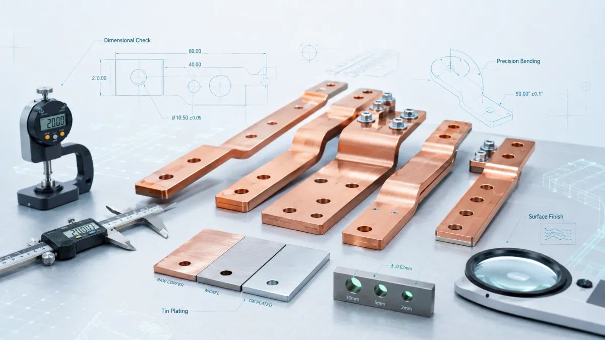
Custom DC busbars are not only designed; they are manufactured through a sequence of processes. The process may include copper strip cutting, punching, CNC bending, deburring, cleaning, welding, terminal pressing, plating, insulation, marking, inspection and packaging. Each process has tolerances.
For rigid busbars, bend accuracy and hole position are key. If holes are punched before bending, the bending process can slightly affect final hole position depending on geometry. If holes are close to bends, deformation risk increases. The drawing should include bend radius, angle tolerance, flatness and critical-to-function dimensions.
For laminated flexible busbars, the end terminals are usually consolidated while the middle section remains flexible. The copper foil thickness, number of layers and terminal bonding method influence current capacity, flexibility and contact performance. The design should define the flexible zone and the rigid terminal zone. It should also avoid bending too close to the welded or pressed end.
For braided busbars, wire diameter, braid width, braid thickness, terminal material and terminal pressing quality matter. A tinned braided connector may be preferred in environments where oxidation resistance is important. The braid should not be crushed or bent in a way that damages wire strands.
For insulated parts, masking is a major production detail. Contact areas must remain clean and conductive. Insulation should stop at a controlled distance from bolt holes and contact surfaces. If the design requires coating over a bend or edge, the edge quality should be good enough to prevent thin spots.
JUMAI’s advantage is that it can discuss the manufacturing process together with the electrical design. This is useful for overseas buyers because small drawing changes can reduce cost, improve yield and shorten delivery time.
Quality inspection and testing
A DC busbar quality plan should match the risk level of the application. For low-risk prototypes, dimensional inspection and visual inspection may be enough. For high-current, high-voltage production parts, more checks are needed.
Common inspection items include:
- Material certificate and copper grade confirmation.
- Thickness, width and length measurement.
- Hole diameter and hole position.
- Bend angle and bend height.
- Flatness of contact surfaces.
- Burr inspection.
- Plating thickness and adhesion.
- Insulation thickness, coverage and adhesion.
- Dielectric withstand test for insulated busbars.
- Resistance or micro-ohm measurement for critical paths.
- Pull or press quality check for braided or laminated terminals.
- Packaging inspection to prevent scratches and deformation during shipping.
For busbars used in solar inverters, PCS cabinets and ESS, traceability is helpful. Batch records, inspection reports and packaging labels can support quality control. If the part is used across multiple cabinet models, revision control becomes important. A small change in hole position, coating mask or plating thickness can affect assembly, so drawings should be managed carefully.
Cost optimization without weakening reliability
Copper cost matters, especially in large power equipment. However, reducing copper without understanding the system can create more expensive problems. The goal should be engineering cost optimization, not simply using less metal.
There are several practical ways to optimize cost:
- Shorten the current path by improving cabinet layout.
- Increase system voltage where the product architecture allows it, reducing current for the same power.
- Use rigid busbars where geometry is stable and flexible busbars only where they add value.
- Select plating only where contact performance requires it.
- Avoid unnecessary 3D bends that increase tooling complexity.
- Standardize hole sizes and copper thickness across product families when possible.
- Use assembly-friendly shapes to reduce labor cost.
- Share annual volume expectations so the supplier can choose the right production method.
A busbar that is slightly more expensive per piece may reduce total cost if it replaces multiple cables, lugs, clamps and manual routing operations. It may also reduce warranty risk by improving joint reliability. This is especially true in PCS cabinets and ESS racks, where repeated assembly and field service are major cost drivers.
How JUMAI supports custom DC bus bar projects
JUMAI focuses on custom copper busbar manufacturing for global customers. For DC bus bar projects in solar inverters, PCS cabinets and energy storage systems, the company can support rigid copper busbars, laminated flexible copper busbars, braided copper busbars, insulated copper busbars, plated contacts and customized punched or bent shapes. This range allows the design to match the real power path instead of forcing one conductor type into every position.
A typical project can begin with a drawing, sample or cabinet layout. The engineering review should confirm copper material, current path, voltage level, surface finish, insulation requirement, hole pattern, bend geometry, tolerance and packaging. If the design is still early, JUMAI can help identify where a rigid bar is suitable and where a flexible or braided solution may reduce assembly stress.
JUMAI’s internal content also gives buyers useful background. The custom copper busbars page summarizes the main product categories. The flexible copper busbar guide explains why flexible conductors are useful in EV batteries, BESS and power distribution. The copper bus bars power distribution article discusses how rigid, flexible and braided structures fit different current paths. The busbar copper article explains why copper is still preferred for many high-current conductors. These internal resources help customers understand the technical language before sending an RFQ.
For overseas OEMs and integrators, communication clarity is important. A good inquiry should include drawings, 3D files, current and voltage requirements, insulation expectations, plating preferences, quantity, target application and any test requirements. With this information, JUMAI can provide a more accurate manufacturing review and quotation.
Example design workflow for a DC bus bar project
A practical DC bus bar design workflow can follow these steps.
First, define the electrical path. Identify where current enters, where it exits and which components are connected. Mark the positive and negative paths separately. Note whether current is continuous, intermittent or bidirectional. In PCS and ESS applications, charging and discharging current may use the same busbar but different operating profiles.
Second, estimate current and loss. Use power and voltage to estimate current, then calculate an initial resistance and heat target. Consider overload and derating. Decide whether the busbar is a main current path, a module branch, a pre-charge path, a sensing point or a grounding conductor.
Third, review the mechanical envelope. Check the cabinet layout, mounting direction, component tolerance and service access. Decide whether a rigid, flexible, braided or hybrid conductor is most suitable. Avoid designing a rigid bar across parts that may move relative to each other.
Fourth, design insulation and safety distance. Define voltage level, creepage, clearance, insulation material, exposed contact areas and test requirement. Do not leave coating decisions until the end. Insulation can change bend feasibility, hole clearance and assembly sequence.
Fifth, define contacts. Select plating, overlap area, hole size, bolt torque and washer type. Keep contact surfaces flat and clean. Avoid putting insulation under the contact area unless the design intentionally uses a shoulder or spacer.
Sixth, review manufacturability. Confirm bend radius, copper thickness, hole position, deburring, welding or pressing method, plating feasibility, coating mask and packaging. Ask the supplier to review the drawing before tooling or mass production.
Seventh, prototype and test. Install the busbar in a real cabinet or representative fixture. Check assembly time, tool access, interference, insulation coverage and temperature rise under load. Use the findings to update the drawing before production.
Eighth, control production. Use a clear revision, inspection plan, packaging method and incoming quality criteria. For high-current systems, consistency is part of safety.
Frequently asked questions
What is the difference between a DC bus bar and a DC link busbar?
A DC bus bar is a broad term for a conductor that distributes direct current. A DC link busbar usually refers to the busbar assembly between the DC link capacitors and the power semiconductor stage in an inverter or PCS module. A DC link busbar often needs low inductance and compact positive-negative layering. A general DC distribution busbar may focus more on ampacity, insulation and service access.
Is a rigid copper busbar always better than a cable?
No. A rigid copper busbar is better when the geometry is fixed, the current is high and repeatable assembly is important. A cable is useful when long routing flexibility is needed. A laminated flexible busbar can be a good middle option when the design needs a defined current path but also needs some bending or tolerance compensation. The best choice depends on the equipment layout and service requirement.
When should a laminated flexible DC busbar be used?
A laminated flexible DC busbar should be considered when the connection must fit inside a compact space, absorb small movement, reduce cable assembly complexity or connect parts with slight positional tolerance. It is also useful when a flat conductor path is preferred but a fully rigid bar would transfer too much stress into terminals.
When should a braided copper busbar be used?
A braided copper busbar is useful for grounding, bonding, vibration zones and connections that need high flexibility. It is commonly used when movement or misalignment is more significant. It may not be the best choice for every high-current DC link because geometry and inductance control may be less precise than a laminated structure.
Does higher DC voltage make the busbar smaller?
For the same power, higher voltage reduces current, and lower current can reduce conductor size and heat loss. However, higher voltage increases insulation and safety distance requirements. A 1,500 Vdc design may use less copper than a lower-voltage design, but it must be more careful about creepage, clearance, edge quality and insulation.
What information should be sent to JUMAI for a quotation?
The best inquiry includes 2D drawings, 3D CAD files, current rating, voltage rating, application location, material requirement, plating requirement, insulation requirement, quantity, test requirement and photos or drawings of the surrounding assembly. If the design is not finalized, sharing the cabinet layout helps JUMAI suggest a better busbar structure.
Design the DC bus bar as part of the whole power system
A DC bus bar is more than a copper connector. In solar inverters, PCS cabinets and energy storage systems, it is part of the electrical, thermal, mechanical and safety design of the complete product. It must carry current with low loss, control temperature rise, maintain insulation distance, support reliable joints and fit the assembly process. As renewable energy and battery storage systems continue to scale, these details become even more important.
The best DC bus bar design begins with clear electrical data and a realistic understanding of the cabinet. Rigid copper busbars are excellent for stable high-current routes. Laminated flexible copper busbars are valuable for compact routing, tolerance compensation and low-stress connections. Braided copper busbars are useful for bonding, grounding and vibration-sensitive areas. Insulated and plated options help improve safety and contact reliability.
JUMAI supports custom DC bus bar projects for solar inverters, PCS cabinets, BESS cabinets, power distribution systems and related high-current equipment. If your project needs a custom copper busbar, flexible laminated busbar, braided connector or insulated rigid busbar, send your drawing, CAD model or application requirements to JUMAI for engineering review and quotation.