In the rapidly evolving landscape of modern electrical engineering, the demand for efficiency, thermal management, and mechanical durability has never been higher. Whether we are discussing the intricate power distribution units in Electric Vehicles (EVs) or the massive energy storage systems (ESS) supporting renewable grids, the traditional rigid busbar is often found wanting. This is where the Flexible Busbar steps in, specifically those manufactured through the sophisticated process of diffusion bonding.
At JUMAI TECH, we have spent years perfecting the art of joining ultra-thin copper foils into a singular, high-performance conductor. A diffusion-bonded flexible busbar is not merely a piece of metal; it is a precision-engineered solution designed to withstand high-vibration environments and extreme thermal cycles while maintaining 100% electrical conductivity. This guide serves as a comprehensive roadmap to understanding why diffusion bonding is the gold standard for flexible interconnects.
Table of Contents
The Evolution of Power Distribution: Why Flexibility Matters
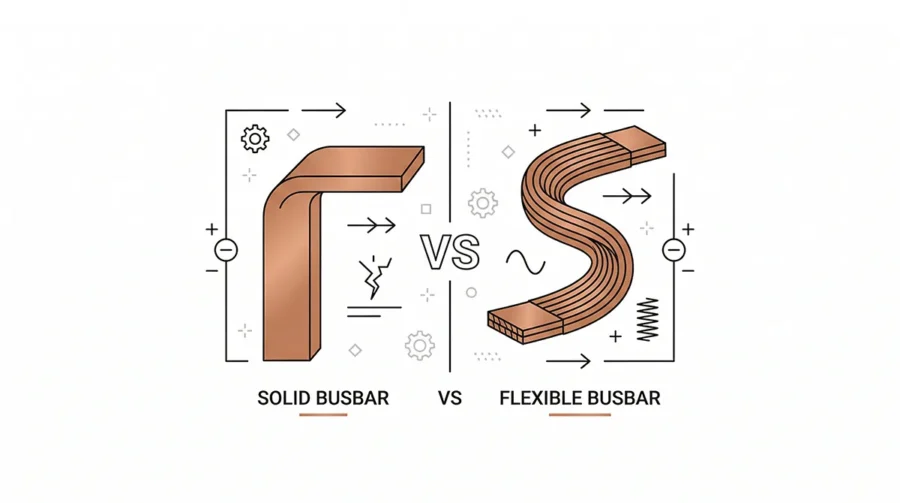
For decades, solid copper bars were the backbone of industrial power. However, as systems became more compact and power densities increased, the industry reached a breaking point. Rigid bars are prone to stress fractures caused by thermal expansion and mechanical vibration. The shift toward a Flexible Busbar architecture was not just a design choice; it was a necessity for system longevity.
Addressing Thermal Expansion and Contraction
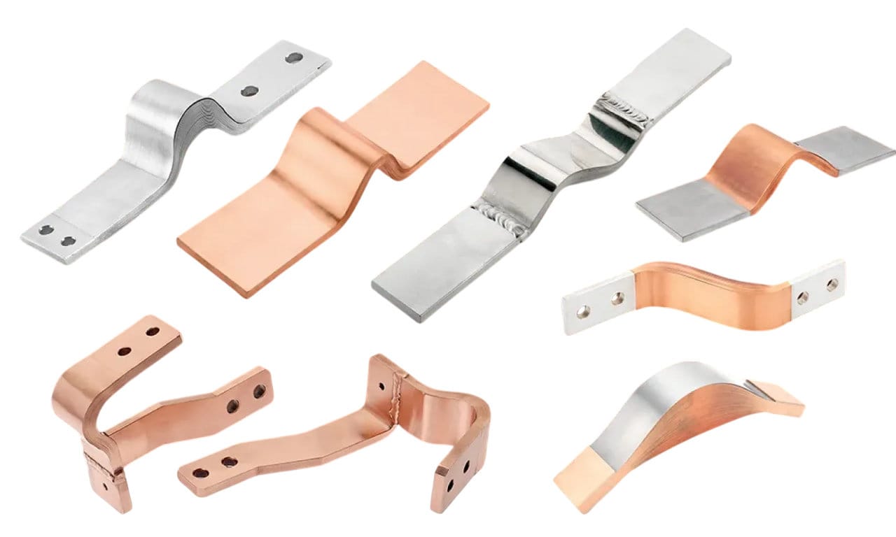
Electrical components generate heat. As temperatures rise, metals expand. In a rigid system, this expansion creates immense stress on connection points and ceramic insulators. Flexible busbars, composed of stacked foils, act like a bellows or a spring. They absorb this linear expansion without transferring the load to the sensitive battery terminals or switchgear components. This “mechanical decoupling” is the primary reason why Tier 1 automotive suppliers insist on flexible solutions for battery pack interconnects.
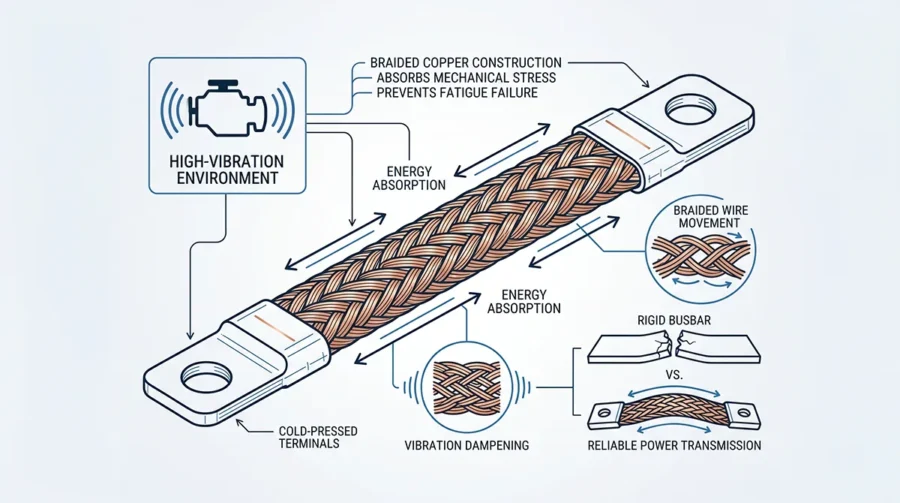
Vibration Dampening in Electric Mobility
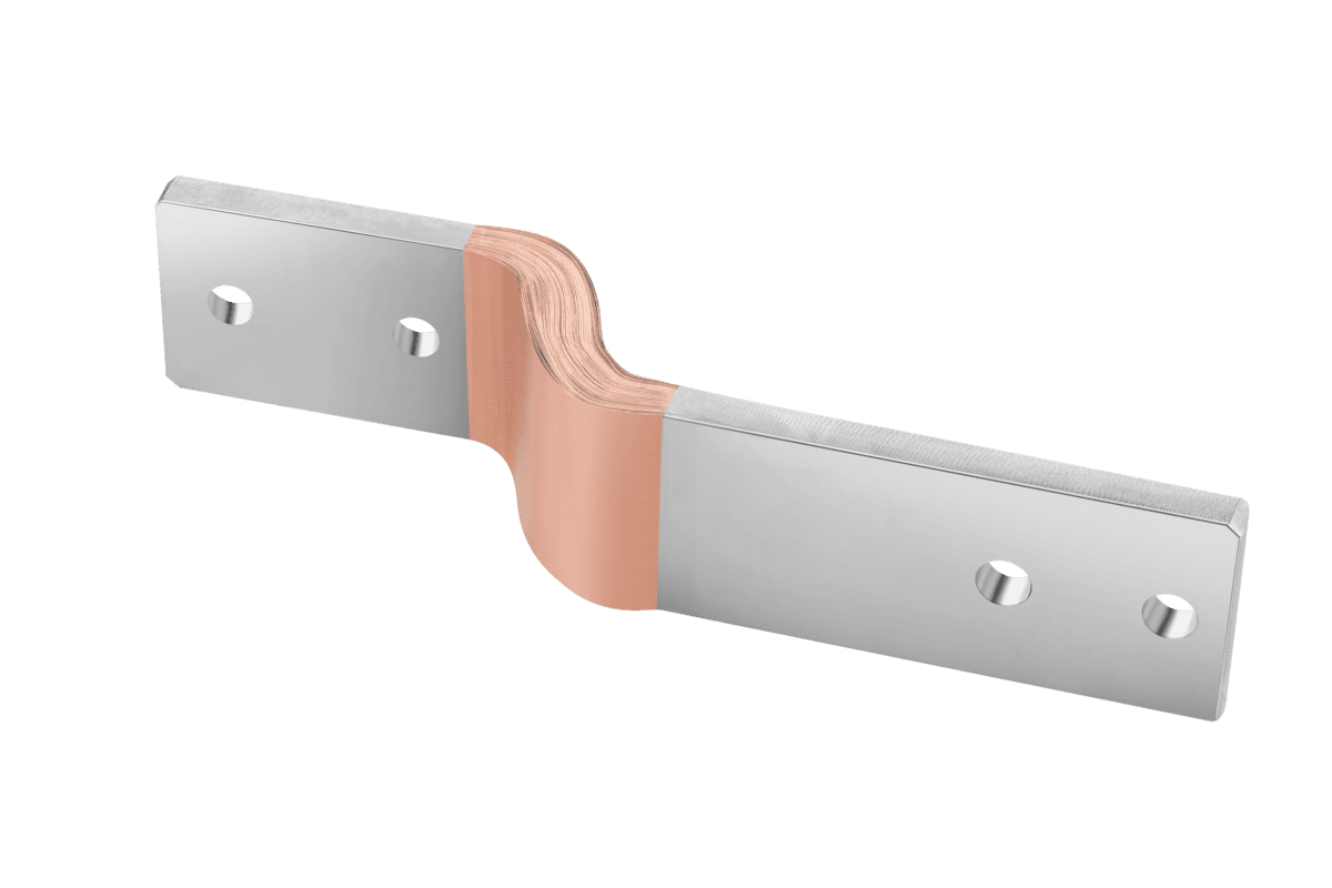
In electric vehicles and rail transport, constant vibration is the enemy of electrical integrity. A rigid connection will eventually loosen or suffer from fatigue cracking. The inherent damping characteristics of a multi-layer flexible busbar dissipate kinetic energy. By utilizing diffusion bonding at the contact areas while leaving the center “bridge” flexible, we provide a component that offers the stability of a solid bar at the joints and the resilience of a cable in the middle.
Decoding Diffusion Bonding Technology
Diffusion bonding is a solid-state joining process. Unlike traditional welding or soldering, it does not require a filler metal or the melting of the base material. For our clients at JUMAI TECH, this means the copper’s purity is maintained, and the electrical resistance at the joint is virtually zero.
The Science of Molecular Migration
The process involves stacking hundreds of thin copper foils (typically 0.1mm to 0.3mm thick) and subjecting them to intense heat and pressure in a controlled environment. According to the ASM International Materials Engineering Institute, diffusion bonding occurs when atoms from the two surfaces migrate across the interface. This creates a continuous grain structure. When you look at a diffusion-bonded joint under a microscope, the interface disappears; the multiple foils have become a single, solid block of copper.
Temperature and Pressure Parameters
To achieve a perfect bond, we carefully calibrate the temperature to approximately 70% to 80% of copper’s melting point. In our facility, we utilize specialized presses that apply uniform force across the entire contact area. This ensures that there are no air pockets or oxidation layers trapped between the foils, which is critical for preventing “hot spots” during high-current operations.
No Filler Metal, No Resistance
One of the most significant advantages of this technique is the absence of solder or welding rods. Conventional welding introduces foreign elements that have higher electrical resistance than pure ETP (Electrolytic Tough Pitch) copper. By using diffusion bonding, we ensure the joint has the same IACS (International Annealed Copper Standard) conductivity as the raw material itself—typically 100-101%.
Material Specifications for High-Performance Flexible Busbars
Quality starts with the raw material. At JUMAI TECH, we don’t just pick any copper. We select materials that meet international standards for purity and mechanical properties to ensure your Flexible Busbar performs under the harshest conditions.
ETP Copper (C11000) vs. OFC Copper (C10200)
Most industrial applications use ETP copper for its excellent conductivity and cost-effectiveness. However, for vacuum applications or environments requiring maximum ductility, Oxygen-Free Copper (OFC) is preferred. OFC prevents “hydrogen embrittlement,” a phenomenon that can occur during high-temperature processing.
| Property | ETP Copper (C11000) | OFC Copper (C10200) |
| Copper Purity | 99.90% Min | 99.95% Min |
| Electrical Conductivity | 100% IACS | 101% IACS |
| Thermal Conductivity | 391 W/m·K | 394 W/m·K |
| Tensile Strength | 220-300 MPa | 220-280 MPa |
Foil Thickness and Flexibility Ratios
The flexibility of the busbar is inversely proportional to the thickness of the individual foils. Using a stack of 0.1mm foils provides significantly more “bendability” and a tighter minimum bend radius than using 0.5mm foils. We typically recommend a standard foil thickness of 0.1mm or 0.2mm for most EV battery applications to maximize the fatigue life of the part.
Designing the Ultimate Flexible Busbar: Key Considerations
When designing a Flexible Busbar for a custom project, engineers must look beyond simple dimensions. You must account for current density, skin effect (in AC applications), and the geometry of the connection points.
Calculating Current Carrying Capacity
The cross-sectional area of the busbar determines how many Amperes it can safely carry without exceeding the temperature rise limits (usually defined by UL 67). A common rule of thumb for copper in open air is approximately 1.2 to 1.5 Amperes per square millimeter for a 30°C temperature rise, but this changes significantly when the busbar is insulated or placed in an enclosed housing.
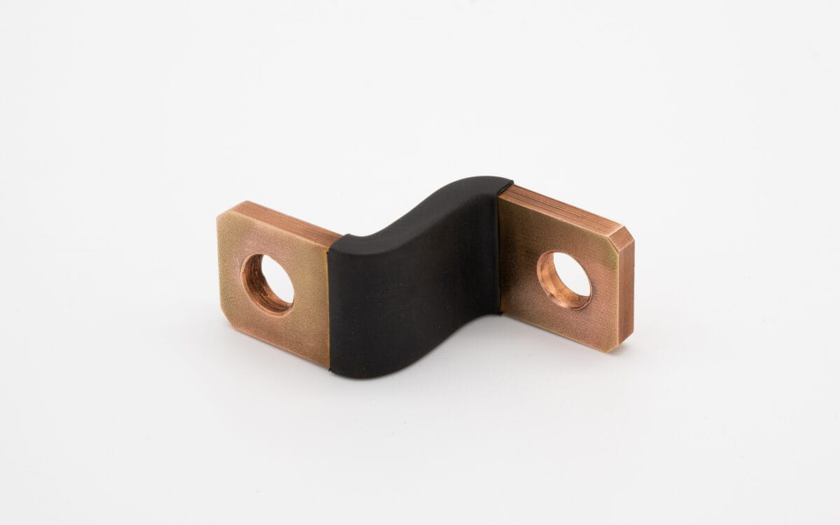
The “Flexible Bridge” Geometry
The length and shape of the non-bonded section (the bridge) are vital. If the bridge is too short, the busbar will be too stiff to absorb vibration. If it is too long, it may sag and cause short circuits with nearby components. We use Finite Element Analysis (FEA) to simulate the stresses on the bridge to ensure that it can withstand thousands of vibration cycles without work-hardening the copper.
Surface Plating: Tin, Nickel, or Silver?
While copper is a great conductor, it oxidizes quickly. To ensure a low-resistance connection over a 20-year lifespan, surface plating is essential.
- Tin Plating: The most common choice; offers great corrosion resistance and is cost-effective.
- Nickel Plating: Preferred for high-temperature environments (above 150°C).
- Silver Plating: The gold standard for high-frequency or ultra-high-efficiency requirements, offering the lowest contact resistance.
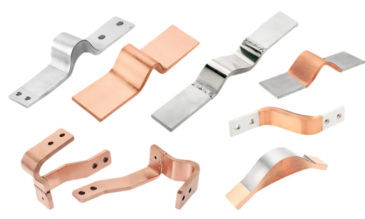
Applications Across Global Industries
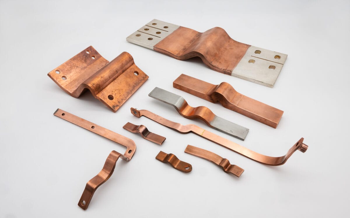
The versatility of the Flexible Busbar has made it a staple in several high-tech sectors. At JUMAI TECH, we see these components being deployed in ways that were unimaginable a decade ago.
Electric Vehicle Battery Packs
In an EV battery, hundreds of cells are linked together. These cells expand and contract during charge/discharge cycles (jelly roll expansion). Diffusion-bonded flexible busbars are used to connect battery modules to the main power distribution unit, ensuring that this expansion doesn’t snap the terminals.
Renewable Energy Inverters
Solar and wind inverters convert DC power to AC. This process involves high-speed switching and significant heat generation. The flexible nature of these busbars allows for compact internal layouts, where rigid bars simply wouldn’t fit due to the tight clearance requirements between capacitors and IGBT modules.
Data Centers and Supercomputing
Modern servers consume massive amounts of power at low voltages. This requires an extremely high current. Flexible busbars allow for “hot-swappable” power modules, where the busbar must be able to slightly misalign and then snap into place when a power supply is plugged into the rack.
The Manufacturing Lifecycle: From Raw Foil to Precision Component
Creating a high-performance Flexible Busbar is a symphony of metallurgical science and mechanical engineering. At our facility, the process is governed by strict tolerances to ensure that every micron of copper contributes to the final efficiency of the system.
Precision Slitting and Layering
The process begins with high-purity electrolytic copper coils. These coils are slit into precise widths using automated machinery. The thickness of these foils—often 0.1mm to 0.2mm—is critical.
- Layer Alignment: To ensure a perfect bond, the foils must be perfectly aligned. Even a 0.5mm deviation can lead to structural weakness or electrical “hot spots” at the connection points.
- Cleaning Protocols: Before bonding, the copper undergoes an ultrasonic cleaning process to remove any surface oils, oxidation, or particulates. According to the International Copper Association (ICA), surface purity is the single most important factor in the success of a solid-state molecular bond.
The Diffusion Bonding Pressing Cycle
Once stacked, the copper foils are placed into our custom-engineered diffusion bonding presses. This is where the transformation occurs.
- Vacuum/Inert Atmosphere: We often perform bonding in a controlled environment to prevent oxidation during the heating phase.
- Thermal Calibration: The temperature is raised to a specific point where atomic diffusion becomes rapid. We maintain this temperature with a tolerance of $\pm 5^{\circ}C$.
- Pressure Application: Hydraulic systems apply thousands of kilonewtons of force. This force collapses the microscopic ridges on the foil surfaces, allowing the atoms to migrate across the grain boundaries.
- Cooling Phase: Controlled cooling is essential to prevent internal stresses and “warping” of the copper stack.
Post-Bonding Machining and Forming
After the ends are bonded into solid blocks, the Flexible Busbar undergoes secondary processing.
- CNC Milling: We use high-speed CNC machines to drill holes or mill slots into the bonded ends. Because the joint is now a solid block, it can be machined with the same precision as a standard rigid bar.
- Bending and Shaping: The center “flexible bridge” is then bent into the required 3D geometry. Our engineers use custom jigs to ensure that the bend radius does not exceed the material’s fatigue limits.
Comparative Analysis: Diffusion Bonding vs. Conventional Joining
In the industry, there are several ways to join copper foils. However, for high-reliability applications, not all methods are created equal. Let’s look at why diffusion bonding is superior to traditional brazing or ultrasonic welding.
Diffusion Bonding vs. Brazing
Brazing uses a filler metal (like silver or phosphorus-copper) to “glue” the foils together. This introduces several problems:
- High Resistance: The filler metal has lower conductivity than pure copper.
- Weight: Brazing adds unnecessary mass.
- Brittleness: The heat-affected zone (HAZ) in brazing can become brittle, leading to cracks under vibration.
| Feature | Diffusion Bonding | Braze Welding |
| Material Continuity | Molecular/Homogeneous | Heterogeneous (Filler used) |
| Electrical Resistance | Equivalent to Base Copper | Higher (at the joint) |
| Weight | No change | Increased by filler |
| Mechanical Strength | 100% of base metal | 70-85% of base metal |
| Corrosion Resistance | Excellent (No galvanic cells) | Moderate (Galvanic risk) |
Diffusion Bonding vs. Ultrasonic Welding
Ultrasonic welding is fast and useful for small wire-to-terminal connections. However, for a thick Flexible Busbar stack (e.g., 50 to 100 layers), ultrasonic waves cannot penetrate deep enough to ensure a uniform bond throughout the entire cross-section. Diffusion bonding remains the only viable method for thick, high-current-capacity flexible conductors.
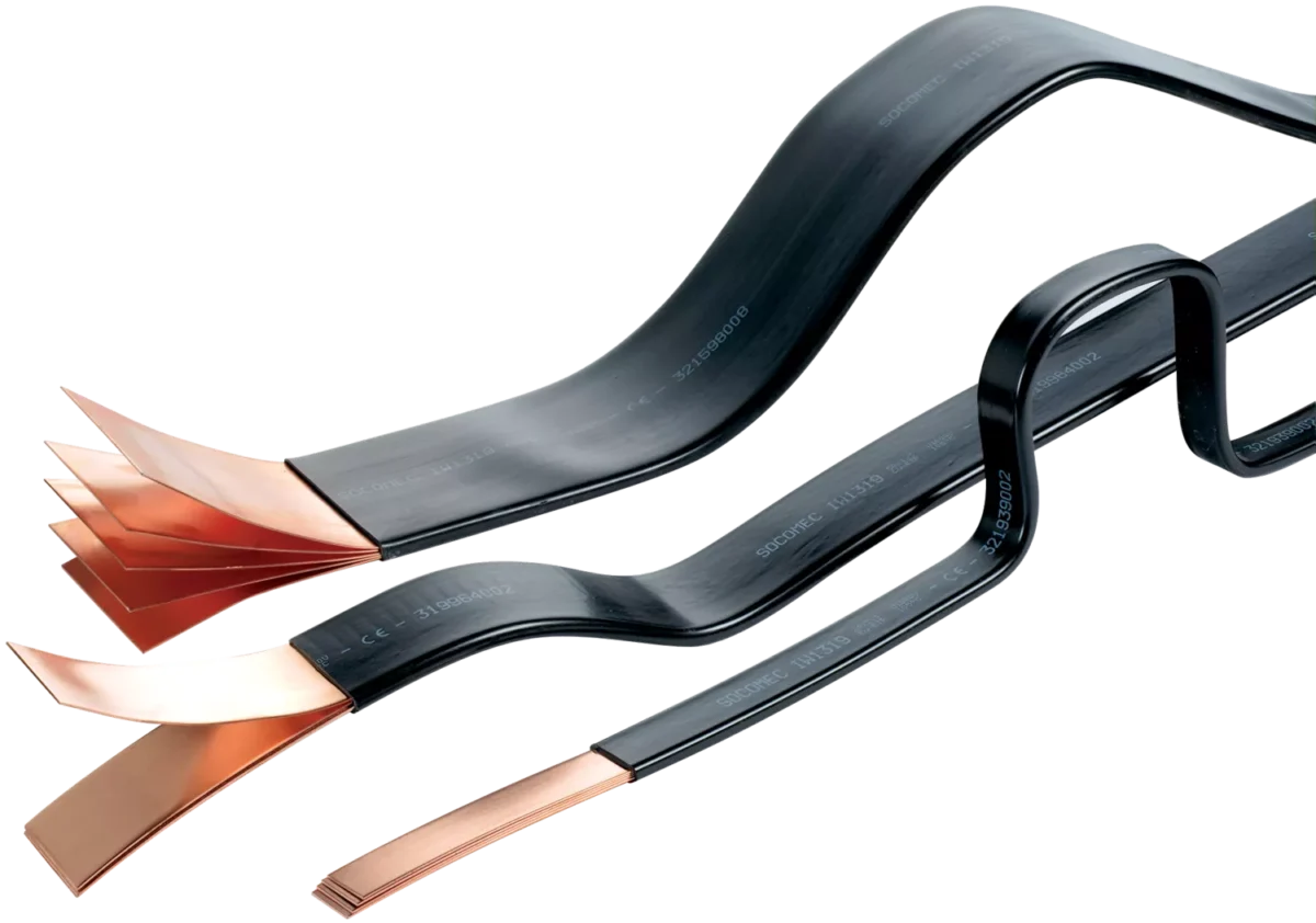
Advanced Insulation Systems for Flexible Busbars
A busbar is only as good as its insulation, especially in the high-voltage environments of 800V EV platforms or 1500V solar arrays. We offer several types of insulation to match your specific environmental needs.
Heat Shrink Tubing (Polyolefin)
This is the most common insulation method. It is cost-effective and provides good dielectric strength. However, for complex 3D shapes, it can sometimes leave air gaps.
PVC Dipping and Coating
For highly complex geometries, dipping the busbar into liquid PVC ensures a seamless, “skin-tight” insulation layer. This is excellent for preventing moisture ingress and provides a high degree of chemical resistance.
High-Performance Polyimide (Kapton) and PET
In aerospace or high-performance EVs, where space is at a premium and temperatures are extreme, we use ultra-thin Polyimide films. These materials offer:
- Dielectric Strength: Up to 150 kV/mm.
- Thermal Stability: Rated for continuous use up to 200°C.
- Space Savings: Allows for thinner overall profiles in compact battery modules.
[Detailed Image: Comparison of Polyolefin vs. Polyimide insulation thickness]
Quality Assurance: The JUMAI TECH Standard
As an ISO 9001 and IATF 16949 certified manufacturer, our quality control process for the Flexible Busbar is exhaustive. We don’t just “hope” the part works; we prove it.
Electrical Integrity Testing
- Micro-Ohm Testing: We measure the resistance across the bonded joint. If the resistance is higher than the calculated value for a solid bar of the same dimensions, the part is rejected.
- Hi-Pot (High Potential) Testing: To ensure the insulation is perfect, we subject the busbar to voltages 2-3 times higher than its operating rating to check for leakage current or dielectric breakdown.
Mechanical and Thermal Reliability
- Pull Testing: We perform destructive testing on sample batches to ensure the bond strength exceeds the tensile strength of the copper itself.
- Thermal Cycling: We put parts through extreme temperature swings (e.g., -40°C to +125°C) to simulate a lifetime of vehicle operation. This ensures the bonding and insulation remain intact despite thermal expansion.
- Salt Spray Testing: For marine or coastal applications, we test our plated busbars in salt fog chambers according to ASTM B117 to verify corrosion resistance.
Optimization for 800V Architecture and Beyond
The industry is moving toward higher voltages to enable faster charging in EVs. This shift places unique demands on the Flexible Busbar.
Managing Skin Effect in High-Frequency Systems
As switching frequencies increase in modern SiC (Silicon Carbide) inverters, current tends to flow on the surface of the conductor (the skin effect). By using multi-layered flexible busbars, we increase the surface-area-to-volume ratio compared to a solid bar, which can help manage heat and efficiency in high-frequency AC environments.
Creepage and Clearance Challenges
Higher voltages require greater distances between conductors to prevent “arcing.” Our design team assists clients in optimizing the geometry of their Flexible Busbar to meet these safety standards while still maintaining a compact footprint.
Sustainable Manufacturing and Material Sourcing
At JUMAI TECH, we recognize our responsibility to the environment. Copper is 100% recyclable, and we ensure that all scrap from our slitting and punching processes is returned to the foundry for recycling.
- Green Energy: Our facility is increasingly powered by renewable sources to reduce the carbon footprint of every busbar we produce.
- Conflict-Free Minerals: We strictly audit our supply chain to ensure all copper and plating materials are ethically sourced.
Partnering with JUMAI TECH for Excellence
Choosing the right Flexible Busbar is not just about choosing a component; it’s about choosing a partner who understands the intricacies of your application. From the initial FEA simulation to the final plating and insulation, our team at JUMAI TECH (deepdrawtech.com) is dedicated to delivering copper solutions that power the future.
Whether you are designing the next generation of electric hypercars, a massive grid-scale energy storage system, or a high-performance industrial inverter, our diffusion-bonded flexible busbars provide the reliability, efficiency, and flexibility your project demands.
Frequently Asked Questions (FAQ)
What is the typical lead time for custom flexible busbars?
For prototypes, our lead time is typically 1-2 weeks. For mass production, it ranges from 4-6 weeks, depending on the complexity of the plating and insulation requirements.
Can you provide flexible busbars with different plating on each end?
Yes, we can offer selective plating solutions, though most clients find that full-surface tin or silver plating is the most cost-effective and reliable method.
How do I determine the best foil thickness for my application?
If your application involves high-frequency vibration (like a truck chassis), 0.1mm foils are best. For more static applications like a stationary battery rack, 0.2mm or 0.3mm foils are often sufficient and more cost-effective.
Do you provide design assistance?
Absolutely. Our engineering team can review your 3D CAD files and suggest optimizations for bend radii, hole placement, and thermal management.