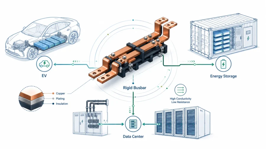
High-current systems are becoming more compact, more power-dense, and more commercially demanding. Electric vehicles, battery energy storage systems, solar and wind inverters, UPS cabinets, data centers, industrial drives, switchgear, and large power conversion equipment all have one thing in common: the conductor is no longer just a piece of metal that connects point A to point B. It is part of the electrical design, the thermal design, the mechanical structure, the installation workflow, the maintenance plan, and the total cost of ownership.
That is why the comparison between Rigid Busbars and Flexible Busbars matters. Both can be correct. Both can be made from high-conductivity copper. Both can carry large current safely when they are engineered properly. The real question is not “Which one is always better?” The better question is: Which busbar type fits the electrical load, mechanical environment, assembly method, service life, and commercial target of this specific system?
At JUMAI, we manufacture custom copper busbars and related precision metal components for applications such as AI servers, EV systems, energy equipment, industrial power distribution, and high-current assemblies. Our work covers soft and rigid copper busbar solutions, custom processing, precision stamping, and deep-drawn accessories. In real projects, we often see buyers make one of two mistakes: they choose rigid busbars because they look stronger, or they choose flexible busbars because they look easier to install. Both decisions are incomplete if they ignore current path, temperature rise, vibration, tolerance stack-up, insulation, contact design, and production repeatability.
This guide explains the difference in a practical way. It is written for engineers, purchasing managers, product developers, project managers, and OEM teams that need a commercially useful answer before sending drawings, 3D files, or RFQ packages to a supplier.
Table of Contents
Why the decision is becoming more important
The market is moving toward higher current and tighter layouts. The International Energy Agency reports that global electricity demand is accelerating, supported by electric vehicles, data centers, advanced manufacturing, space cooling, and other electrified loads. In its Electricity 2026 analysis, the IEA projects global electricity consumption to reach 33,600 TWh in 2030, up from 28,200 TWh in 2025. That means more electrical equipment, more conversion stages, more cabinets, more battery modules, more inverter links, and more high-current interconnects.
Data centers are a clear example. The IEA’s report on energy and AI projects that data center electricity consumption could roughly double from 485 TWh in 2025 to 950 TWh in 2030, while AI-focused data center electricity consumption grows faster than the overall data center sector. A busbar inside a UPS, power distribution unit, switchboard, battery cabinet, or server power architecture may look small compared with the entire facility, but multiplied across thousands of modules, small differences in heat, assembly time, layout density, and service reliability become meaningful.
Electric vehicles and battery systems create the same pressure from another direction. The IEA’s Global EV Outlook 2025 states that electric car sales exceeded 17 million globally in 2024 and represented more than 20% of new car sales. More EVs mean more battery packs, more module-to-module connections, more inverter links, more DC fast charging infrastructure, and more high-current conductors that must tolerate vibration, temperature cycling, compact packaging, and safety validation.
Battery storage is also growing. The U.S. Energy Information Administration publishes regular battery storage market updates covering large-scale battery storage capacity, co-location, installation costs, and applications served. For BESS manufacturers and integrators, busbar selection is not only an electrical choice. It affects cabinet density, thermal management, installation labor, service access, and the ability to repeat a design across many containers or cabinets.
| High-current market pressure | Why it changes busbar selection | Practical design consequence |
|---|---|---|
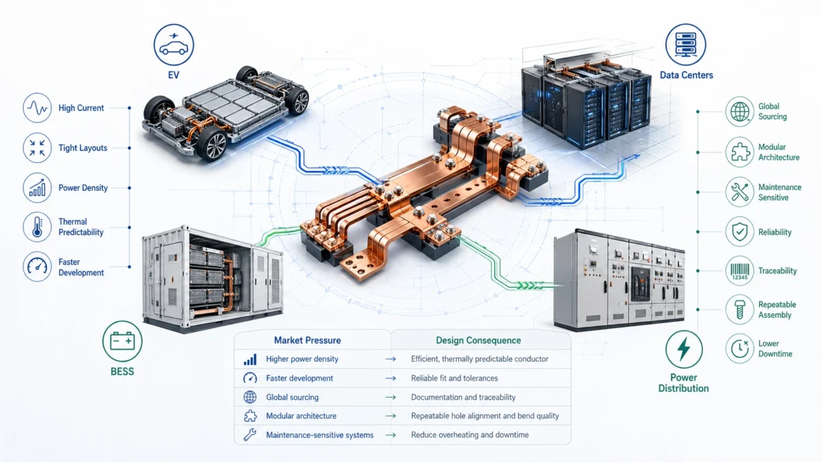
| Higher power density in EVs, BESS, UPS, and data centers | More current must pass through limited space | The conductor must be electrically efficient and thermally predictable |
| Faster product development cycles | Engineering teams need fewer redesign loops | Busbars must fit drawings, tolerances, and assembly sequences reliably |
| Globalized sourcing | OEMs compare suppliers across regions | Documentation, inspection, plating, insulation, and traceability matter |
| Modular power architecture | The same connection may repeat hundreds or thousands of times | Repeatable forming, hole alignment, bend quality, and packaging become cost drivers |
| Maintenance-sensitive systems | Downtime is expensive | The design must reduce overheating, loose joints, vibration damage, and difficult inspection |
This is the background behind the rigid-versus-flexible decision. The conductor is no longer selected only by ampacity. It must help the whole system become smaller, safer, easier to build, easier to inspect, and more commercially competitive.
Basic definitions: what we mean by rigid and flexible busbars
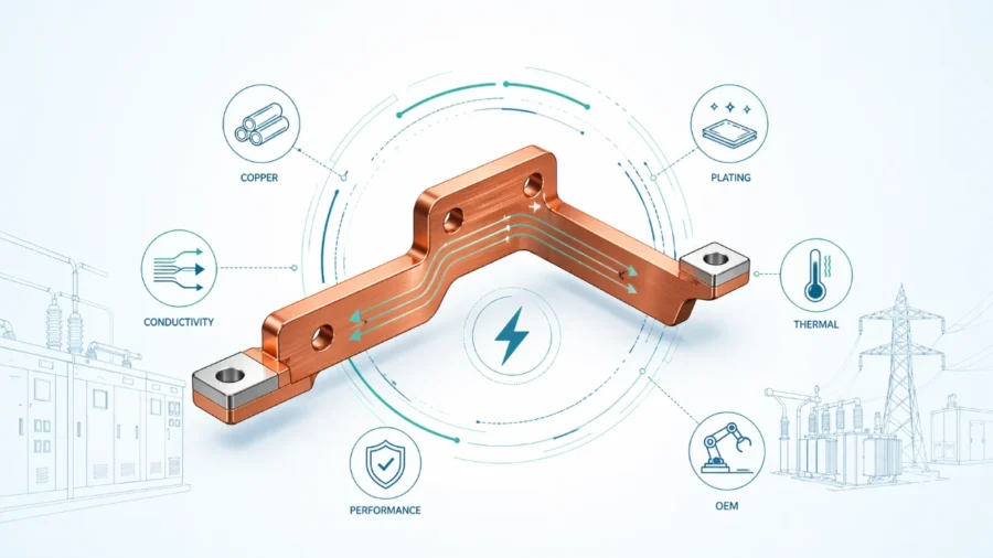
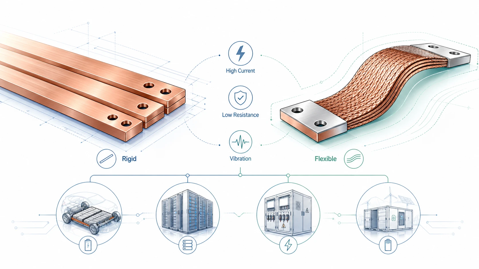
A Rigid Busbar is a solid conductor, usually made from copper or aluminum, formed into a fixed shape. It can be flat, bent, punched, plated, insulated, laminated, or integrated with other mechanical features. In high-current copper applications, rigid busbars are often made from C11000 / ETP copper or other specified copper grades, depending on conductivity, forming, plating, and customer requirements. A rigid busbar is excellent when the current path is fixed, the terminals are stable, the assembly has clear mechanical references, and the conductor should also contribute to structural order.
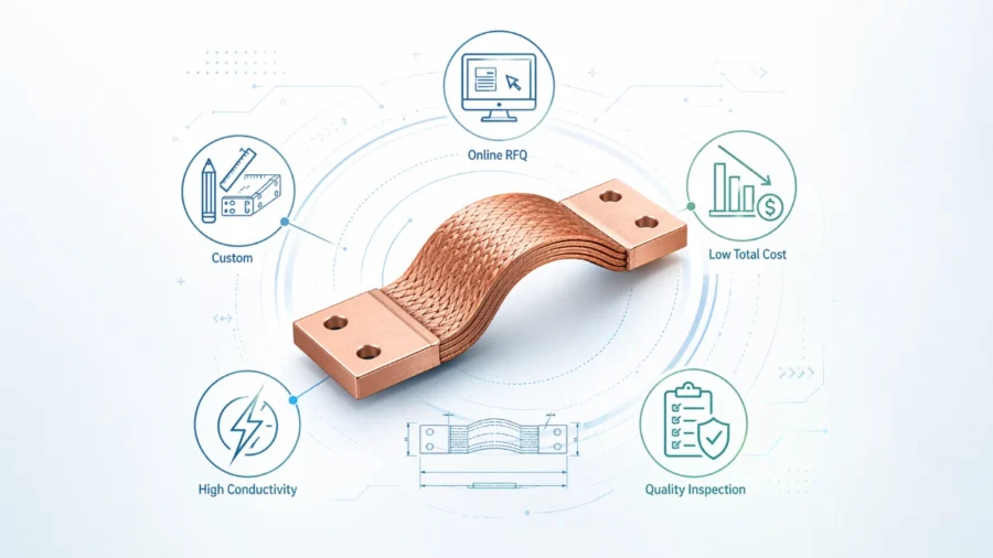
A Flexible Busbar is designed to tolerate movement, installation misalignment, thermal expansion, vibration, or repeated mechanical stress. Flexible busbars may be laminated from thin copper foils, made from braided copper wires, or designed as soft copper links with formed ends. The exact construction depends on the application. A flexible laminated busbar may provide controlled bendability in a compact battery pack, while a braided busbar may be better for vibration isolation between moving or vibrating equipment.
In simple terms, rigid busbars create a fixed, clean, mechanically stable power path. Flexible busbars create a more forgiving power path that can absorb motion, misalignment, vibration, and thermal movement.
| Busbar type | Basic structure | Best-known advantage | Common limitation |
|---|---|---|---|
| Rigid copper busbar | Solid copper strip/bar, cut, punched, bent, plated, insulated as needed | High layout control, compact routing, good heat dissipation, repeatable assembly | Poor tolerance for movement if the connected components shift or vibrate |
| Laminated flexible busbar | Multiple thin copper foils stacked and joined at terminals | Controlled flexibility, lower stress on terminals, useful in battery and power modules | More process variables: foil count, terminal joining, insulation, bend limits |
| Braided copper busbar | Woven fine copper wires with pressed or welded terminals | Strong vibration absorption and movement tolerance | Less geometrically precise than a rigid formed bar |
| Hybrid busbar | Rigid sections plus flexible sections or attached flexible links | Balances layout control and mechanical stress relief | Requires careful interface and process design |
The best supplier should not push one type blindly. A strong supplier should ask how the busbar will be installed, what movement it will see, how much current it carries, what temperature rise is acceptable, how terminals are fastened, whether plating is needed, what insulation system is required, and what documentation must be delivered with production.
Electrical performance: resistance, voltage drop, and heat
The first job of any busbar is to carry current with acceptable electrical loss and acceptable temperature rise. Copper is widely used because of its high electrical conductivity. The Copper Development Association explains that copper conductivity is commonly expressed as a percentage of IACS, the International Annealed Copper Standard, and the organization’s busbar ampacity guidance uses rectangular Copper No. 110 with nominal conductivity of 99% IACS for ampacity tables.
The core physics is easy to understand. Resistance creates heat. In a high-current conductor, heat rises according to the relationship P = I²R. Because current is squared, a small increase in resistance can create a much larger increase in heat at high current. This is why material selection, cross-section, surface condition, bolted joint quality, plating, and manufacturing precision matter. A poorly punched hole, a burr at the contact surface, a warped bend, insufficient plating, or weak terminal compression can all increase resistance at the exact place where the system is already under stress.
Rigid busbars often perform very well electrically because they provide a predictable cross-section, a stable contact area, and good heat dissipation. A flat rectangular conductor has broad surface area, so it can release heat into surrounding air more effectively than many compact round conductors. JUMAI’s own copper busbar ampacity guide explains the importance of heat dissipation through convection, radiation, and conduction, and why rectangular shapes are common in high-current designs.
Flexible busbars can also perform very well, but their construction must be understood. A laminated flexible busbar made from thin copper foils can provide excellent conductivity while reducing mechanical stress. A braided busbar has many fine wires, which can offer high surface area and vibration tolerance. However, flexible structures introduce extra engineering variables: foil thickness, foil count, braid density, terminal compression, weld quality, insulation thickness, bend radius, and fatigue life. If these variables are controlled properly, flexible busbars can be highly reliable. If they are not controlled, the same flexibility that helps installation can become a source of inconsistency.
| Electrical factor | Rigid busbar tendency | Flexible busbar tendency | What buyers should specify |
|---|---|---|---|
| DC resistance | Very predictable when cross-section and copper grade are fixed | Predictable if foil/braid structure and terminal joining are controlled | Copper grade, cross-section, thickness, width, foil count or braid specification |
| Voltage drop | Usually low and stable in fixed routing | Low when designed with sufficient copper mass and good terminals | Maximum allowable voltage drop under continuous current |
| Temperature rise | Often easier to model because shape and surface area are stable | Depends more on insulation, bend shape, stacking, and airflow | Current profile, ambient temperature, cooling condition, acceptable temperature rise |
| Contact resistance | Strong when flatness, plating, hole quality, and torque are controlled | Strong if terminal pressing/welding creates a solid contact zone | Contact surface finish, plating type, hole tolerance, torque assumptions |
| Short-time peak current | Strong if the bar is mechanically supported | Strong if terminals and copper section are sized correctly | Continuous current, peak current, fault-current exposure, duration |
A useful commercial point follows from this table: the cheapest quotation is often not the lowest-cost solution. A busbar that is 5% cheaper but runs hotter, needs rework, fails validation, or requires redesign can become far more expensive than a better-engineered part.
Thermal behavior: why temperature rise is a buying issue, not only an engineering issue
Temperature rise is one of the most important reasons to compare rigid and flexible busbars carefully. It is also one of the most common reasons projects move from a simple drawing quote to a real engineering review.
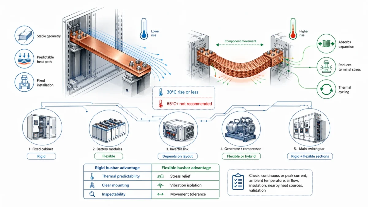
The Copper Development Association recommends that, for energy-efficiency considerations, a busbar system should be designed around a 30°C rise above ambient or less, and notes that temperature rises above 65°C are not recommended and are not energy-efficient. This does not mean every application must use the same limit. Automotive, industrial, switchgear, power electronics, and battery systems can have different standards and validation rules. But it does show the principle: a cooler conductor usually means lower losses, better long-term reliability, and less thermal stress on insulation and nearby components.
Rigid busbars are easier to keep thermally predictable when the installation is fixed. Their geometry is stable, their mounting points are clear, and their surface area can be modeled more directly. If the bar is placed in free air or in a ventilated cabinet, the designer can work with thickness, width, spacing, orientation, plating, and insulation coverage to control temperature rise. In many switchgear and industrial cabinet designs, this predictability is a strong reason to choose rigid busbars.
Flexible busbars can reduce thermal stress in a different way. When two components expand at different rates, a rigid link may transfer that stress into the terminals. A flexible link can absorb the expansion, protecting the joint from mechanical loading. In an EV battery pack or BESS module, where thermal cycling is constant, this can be a major reliability benefit. A flexible busbar may not always look as clean as a rigid bar, but it can protect the electrical joint from stress that would otherwise cause loosening, fretting, or fatigue.
A simplified thermal comparison helps illustrate the trade-off.
| Scenario | Rigid busbar advantage | Flexible busbar advantage | Better starting choice |
|---|---|---|---|
| Fixed cabinet busbar with stable supports | Stable geometry and easy heat path | Less important unless installation tolerance is difficult | Rigid busbar |
| Battery modules with thermal expansion | May need stress-relief design | Absorbs movement and reduces terminal stress | Flexible busbar |
| Inverter link with tight space and controlled airflow | Compact, low-inductance routing is possible | Useful where terminals do not align perfectly | Depends on layout |
| Generator or compressor connection | Can over-transfer vibration | Strong vibration isolation | Flexible or hybrid busbar |
| High-current switchgear main distribution | Clean routing, strong support, inspectable joints | Used selectively for expansion or vibration breaks | Rigid with flexible sections if needed |
For purchasing teams, the message is simple: ask the supplier how they judge temperature rise. A serious supplier should not only say “our busbar can carry 1000 A.” They should ask whether that is continuous or peak current, whether airflow is natural or forced, what ambient temperature is expected, what insulation will cover the copper, how close the busbar is to other heat sources, and how the assembly will be validated.
Mechanical behavior: fixed precision versus controlled movement
Mechanical behavior is where the difference becomes very clear. A rigid busbar is strong, stable, and precise. A flexible busbar is forgiving, stress-relieving, and motion-tolerant. Neither is automatically superior. They solve different mechanical problems.
Rigid busbars are excellent when the assembly has accurate mounting points and the power path should be repeatable. For example, a cabinet manufacturer may want a busbar that drops into the same position every time, aligns with breaker terminals, preserves clearance and creepage distance, and allows workers to tighten bolts without manually routing cables. A rigid busbar can simplify training and reduce assembly variation because the part itself defines the route.
Flexible busbars are excellent when the assembly is not perfectly static. Battery modules may move slightly during vibration. Large equipment may expand and contract during heating and cooling. Motors, compressors, generators, wind turbines, and transportation systems generate vibration. Even a small repeated movement can damage a rigid connection over time if the stress is concentrated at the terminal. Flexible copper structures distribute that stress across foils or braid instead of forcing the terminal to absorb it.
This is why our guide to braided flexible copper busbars in high-vibration environments is commercially relevant. High vibration does not only threaten the conductor body. It threatens bolt torque, terminal flatness, contact resistance, insulation wear, and nearby component life. Flexible busbars help decouple one vibrating component from another.
| Mechanical question | Why it matters | Rigid busbar answer | Flexible busbar answer |
|---|---|---|---|
| Are both terminals fixed and accurately located? | Misalignment creates assembly stress | Excellent if locations are controlled | More forgiving if tolerance stack-up is large |
| Will the connected equipment vibrate? | Vibration can loosen joints and create fatigue | Requires strong support or flexible break | Naturally better for vibration isolation |
| Will there be thermal expansion? | Expansion can load terminals | Needs expansion loop, slot, or flexible section | Absorbs movement more easily |
| Must the power path support structure? | Some assemblies benefit from conductor stiffness | Strong advantage | Usually not the main purpose |
| Is repeated service/disassembly expected? | Rework can bend or damage conductors | Stable if handled correctly | More tolerant, but terminals still need care |
The mistake is to treat “rigid” as “more reliable” in every situation. Rigid busbars are more reliable in stable, controlled installations. Flexible busbars are more reliable where the problem is movement.
Space, layout, and assembly efficiency
One of the strongest commercial arguments for Rigid Busbars is layout control. A rigid busbar can replace a messy cable path with a clean, repeatable, engineered conductor. In high-volume production, this matters because assembly labor is not only the time spent installing a part. It also includes training, checking, rerouting, rework, fixture design, inspection, and troubleshooting.
Rigid busbars are often better when a factory wants a “drop-in” power conductor. Hole locations, bends, offsets, plating zones, and insulation windows can be defined in a drawing. Once tooling and process control are stable, every part should arrive with the same form. That helps the assembly team reduce variation. It also helps the quality team inspect the product quickly.
Flexible busbars improve assembly efficiency in a different way. They reduce the need for perfect alignment. If two terminals are slightly out of position, a flexible link may still fit without forcing the installer to bend or stress a rigid part. In lower-volume or variable builds, this can reduce installation friction. In battery packs and modular systems, flexible links can also protect terminals during assembly because they do not force all geometry into one hard path.
For many high-current systems, the best answer is not purely rigid or purely flexible. A hybrid design may use rigid copper for the main distribution path and flexible copper for module transitions, vibration zones, or thermal-expansion breaks. This can give the system the clean layout of rigid conductors and the stress relief of flexible conductors.
| Assembly requirement | Preferred solution | Reason |
|---|---|---|
| High-volume cabinet with fixed breaker positions | Rigid busbar | Repeatable alignment and faster installation |
| Battery modules with small position variation | Flexible busbar | Protects terminals and absorbs tolerance stack-up |
| Large switchgear with long runs and thermal expansion | Rigid plus flexible expansion sections | Maintains structure while reducing thermal stress |
| Generator to switchgear connection | Flexible or braided busbar | Isolates vibration |
| Compact inverter with strict low-inductance layout | Rigid laminated or formed busbar, sometimes with flexible links | Controls electrical path and package size |
A good RFQ should therefore include more than dimensions. It should include how the part is installed. If the supplier knows the assembly sequence, torque access, nearby parts, expected handling, and service requirements, the supplier can suggest better bend directions, terminal shapes, slot patterns, insulation windows, and packaging methods.
Insulation, plating, and contact surfaces
The copper body carries current, but the surface system determines how the busbar survives in the real world. Plating, insulation, edge quality, burr control, and terminal flatness can decide whether the busbar is easy to validate or difficult to trust.
Rigid busbars may be bare copper, tin-plated copper, nickel-plated copper, silver-plated copper, powder coated, heat-shrink insulated, wrapped, laminated, or selectively insulated depending on the voltage, environment, contact design, and assembly clearances. Tin plating is common where oxidation resistance and stable contact performance are needed at reasonable cost. Nickel or silver may be selected for more demanding thermal, corrosion, or contact requirements.
Flexible busbars need the same surface thinking, but with extra attention to bend zones and terminal transitions. If a laminated busbar is insulated, the insulation must tolerate bending without cracking, lifting, or losing dielectric performance. If a braided busbar is plated, plating quality must reach the relevant strand or terminal surfaces. If the terminal is pressed, welded, or brazed, the terminal zone must be dense, flat, and consistent enough for a low-resistance joint.
Contact surfaces deserve special attention. A busbar can have enough copper cross-section and still fail because the joint is poor. Burrs around holes, uneven plating, poor flatness, scratches, contamination, and incorrect hole tolerances can reduce real contact area. As resistance rises at the joint, heat concentrates at the most dangerous location.
| Surface / interface item | Why it matters | What to request from the supplier |
|---|---|---|
| Plating type and thickness | Affects oxidation, contact resistance, solderability, and corrosion behavior | Tin, nickel, silver, or other plating specification with thickness range |
| Contact flatness | Determines real contact area under bolt torque | Flatness requirement for terminal pads |
| Hole quality | Burrs and ovality affect assembly and contact pressure | Hole diameter tolerance, deburring method, inspection plan |
| Edge condition | Sharp edges can damage insulation and create safety risks | Edge radius, chamfer, or deburring standard |
| Insulation window | Contact areas must remain clean and exposed | Clear drawing showing coated and uncoated zones |
| Batch traceability | Helps quality teams investigate problems | Material certificate, plating batch, inspection records, labeling |
This is where JUMAI’s wider manufacturing capability matters. Our experience in precision stamping dies, deep drawn metal stamping design, and copper busbar processing helps us evaluate not only the conductor shape but also the forming route, tooling risk, burr direction, terminal quality, plating sequence, and inspection practicality.
Standards and validation thinking
A custom busbar is usually part of a larger system. It may not be certified by itself in the same way as a complete panelboard, switchgear assembly, inverter, charger, or battery pack, but its design must support the standards and validation requirements of that system.
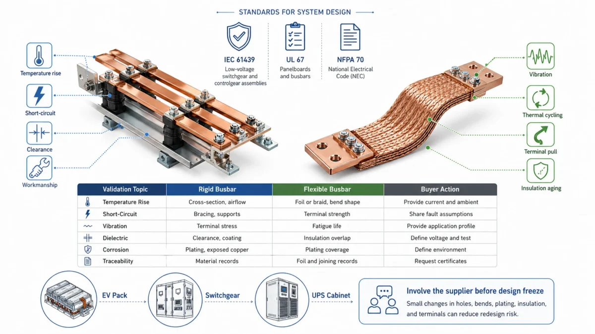
For low-voltage switchgear and controlgear assemblies, IEC 61439 is widely used as a reference framework for design verification. For panelboards in North America, UL 67 covers panelboards intended to be employed in accordance with the National Electrical Code, NFPA 70. These standards are not a replacement for project-specific engineering, but they show why busbar design must consider temperature rise, short-circuit behavior, clearance, creepage, material suitability, and workmanship.
In real projects, the buyer should clarify which standards, customer specifications, or validation plans apply. The supplier does not need to guess. If the busbar is for an EV pack, the validation logic may focus on vibration, thermal cycling, dielectric strength, insulation aging, and terminal pull strength. If it is for switchgear, the focus may include temperature rise, fault current, spacing, support, and assembly verification. If it is for a data center UPS cabinet, continuous current, thermal imaging access, cabinet airflow, and maintenance procedures may be critical.
| Validation topic | Rigid busbar concern | Flexible busbar concern | Buyer action |
|---|---|---|---|
| Temperature rise | Cross-section, airflow, support, insulation coverage | Foil/braid structure, terminals, insulation, bend shape | Provide current profile and ambient condition |
| Short-circuit withstand | Mechanical bracing and supports | Terminal strength and movement under force | Share fault-current and duration assumptions |
| Vibration | Stress at terminals if movement is present | Fatigue life of foil/braid and terminal transition | Provide vibration profile or application category |
| Dielectric performance | Coating thickness, edge radius, clearance | Insulation flexibility, cracks, overlap, termination | Define voltage, creepage/clearance, and test method |
| Corrosion | Plating and exposed copper | Plating coverage across flexible structure | Define operating environment and salt/humidity exposure |
| Traceability | Material and plating records | Material, foil/braid, terminal, joining records | Request certificates and inspection data |
The best way to reduce validation risk is to involve the supplier before the design is frozen. Small changes to hole size, bend radius, terminal width, plating zone, foil count, slot design, or insulation window can prevent expensive redesign later.
Application-by-application comparison
A broad comparison is useful, but buyers usually need an application answer. Below are practical recommendations for common high-current systems.
EV battery packs and module connections
Flexible busbars are often the safer starting point for battery module connections because they tolerate module movement, vibration, and thermal expansion. A battery pack is not a perfectly static structure. Cells and modules experience thermal cycling, road vibration, assembly tolerance, and service handling. A rigid connection may be acceptable in some fixed internal locations, but module-to-module or pack-level transitions often benefit from flexible copper.
Rigid busbars still have a strong role in EV systems. They can be used for stable distribution paths, fuse links, fixed power rails, inverter connections, and areas where package geometry is tightly controlled. The decision depends on whether the connection must absorb movement or define a fixed current path. JUMAI’s article on key design specifications for flexible copper busbars in electric vehicles is a useful internal reference for EV-oriented design thinking.
Battery energy storage systems
BESS designs often use both rigid and flexible busbars. Rigid busbars work well for main cabinet distribution, rack-level power paths, and stable DC bus connections. Flexible busbars work well between modules, drawers, or sections that experience tolerance variation, thermal expansion, or service movement. For a containerized energy storage system, repeatability is commercially important because the same electrical architecture may be produced many times. That makes drawing control, plating, packaging, and batch consistency essential.
Data centers, UPS, and power distribution units
Rigid busbars are usually preferred for clean, high-density power distribution in cabinets, UPS systems, and PDUs when the conductor route is fixed. They help maintain airflow paths, reduce cable clutter, and simplify inspection. In a data center environment where thermal predictability and uptime matter, rigid busbars can make power architecture more organized and serviceable.
Flexible busbars still matter in data center infrastructure. Connections to generators, transformers, cooling equipment, or equipment subject to vibration may require flexible links. Hybrid design is common: rigid for controlled distribution, flexible for stress isolation.
Solar and wind power equipment
Solar inverter cabinets, combiner systems, and power conversion modules often use rigid copper busbars for compact layout and stable thermal behavior. However, large solar farms can see wide temperature swings, and inverter cooling fans can introduce vibration. Flexible sections may be needed where thermal expansion or component movement creates stress.
Wind power applications often favor flexible or braided copper at vibration-sensitive points. A wind turbine nacelle is a dynamic environment. Generator vibration, tower motion, and temperature cycling can punish rigid connections if they are not designed with stress relief.
Industrial drives, automation, and switchgear
Rigid busbars are very strong in industrial drives and switchgear where the cabinet architecture is fixed. They can create short, direct, low-resistance paths between breakers, contactors, drives, capacitors, and terminals. They are easier to inspect visually than many hidden cable paths and can be designed for controlled clearances.
Flexible busbars are useful around motors, compressors, presses, fans, pumps, and other equipment that moves or vibrates. They can also help when field installation tolerance is difficult.
| Application | Better default | Where the other option still fits |
|---|---|---|
| EV module-to-module connection | Flexible busbar | Rigid for fixed rails or protected internal paths |
| BESS rack main distribution | Rigid busbar | Flexible for module drawers or tolerance relief |
| UPS cabinet main DC path | Rigid busbar | Flexible for generator/transformer vibration isolation |
| Solar inverter internal link | Rigid or laminated busbar | Flexible for thermal movement or misalignment |
| Wind turbine generator connection | Flexible or braided busbar | Rigid only with proper stress relief and support |
| Switchgear main bus | Rigid busbar | Flexible expansion joints where needed |
| Industrial motor connection | Flexible busbar | Rigid for fixed cabinet distribution |
Cost comparison: unit price versus total cost
Rigid busbars often look attractive because the structure is simple: cut, punch, bend, finish, inspect, package. For stable geometries and medium-to-high quantities, they can be very cost-effective. Their assembly benefits can also reduce labor cost, especially when they replace manual cable routing.
Flexible busbars may have a higher unit price because of foil stacking, braid formation, terminal pressing, welding, insulation, or more complicated process control. But a higher unit price can be justified when flexibility prevents terminal damage, reduces warranty risk, saves installation time, or avoids redesign caused by tolerance stack-up.
A purchasing team should compare total cost rather than line-item price. The real cost includes copper mass, processing cost, tooling, plating, insulation, quality inspection, packaging, assembly time, rework risk, validation delay, warranty exposure, maintenance frequency, and supplier engineering support.
| Cost factor | Rigid busbar | Flexible busbar | Commercial interpretation |
|---|---|---|---|
| Copper material | Efficient if geometry is optimized | May need extra copper depending on braid/foil design | Optimize by current profile, not by guesswork |
| Processing | Cutting, punching, bending, deburring, plating | Foil/braid process plus terminal joining and insulation | Flexible designs may have more process steps |
| Tooling | Can be low or moderate depending on shape and volume | May need fixtures for terminal compression and repeatability | Tooling should be evaluated against production volume |
| Assembly labor | Often low in fixed layouts | Often low when alignment is variable | Different savings come from different conditions |
| Rework risk | Low if tolerances are controlled | Low if terminal and bend design are controlled | Supplier process discipline matters more than type |
| Maintenance risk | Low in static systems | Lower in dynamic systems | Match the busbar to the failure mode |
One of the most useful questions to ask is: What problem are we paying to avoid? If the main problem is cable clutter and slow assembly, a rigid busbar may be the best investment. If the main problem is vibration fatigue, misalignment, or thermal expansion, a flexible busbar may be the lower-risk investment even if the part price is higher.
Procurement checklist: what to send before requesting a quotation
A good quotation starts with good information. If a supplier quotes only from width, thickness, and quantity, the quotation may look fast but it may hide risk. For high-current systems, JUMAI prefers to review both technical and commercial context so we can suggest a busbar that fits the application rather than simply copying an incomplete drawing.
Before requesting a quote, prepare the following information where possible.
| RFQ item | Why it matters |
|---|---|
| 2D drawing with dimensions and tolerances | Defines hole positions, bends, critical dimensions, and inspection points |
| 3D model or assembly layout | Helps check collision, routing, terminal access, and bend feasibility |
| Continuous current and peak current | Determines copper cross-section and temperature-rise risk |
| Ambient temperature and cooling condition | Influences ampacity and insulation choice |
| Voltage and insulation requirement | Controls clearance, creepage, coating, tubing, and dielectric testing |
| Copper grade or conductivity requirement | Affects resistance, forming, and certification |
| Plating requirement | Controls corrosion resistance and contact performance |
| Terminal hardware and torque assumptions | Affects hole design, contact area, and joint resistance |
| Vibration or movement condition | Determines whether rigid, flexible, braided, or hybrid design is safer |
| Annual volume and sample quantity | Determines tooling strategy and production route |
| Documentation requirement | Defines material certificates, inspection reports, FAI, PPAP-style records, or batch labels |
| Packaging and shipping constraints | Protects plating, insulation, bends, and terminal flatness during transportation |
This checklist is especially important for custom online orders. Buyers sometimes upload a drawing and ask only for the lowest price. That may work for simple parts, but high-current busbars are functional components. If the supplier does not understand the application, the buyer carries the engineering risk.
Supplier evaluation: what separates a strong busbar manufacturer from a parts trader
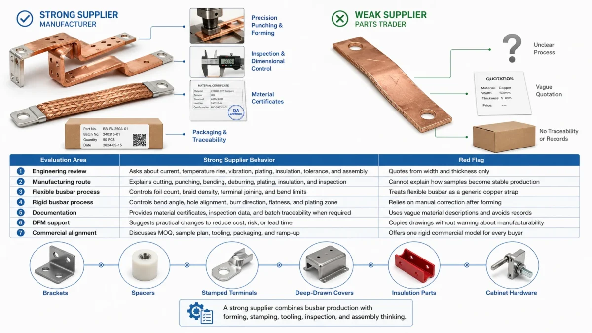
Rigid and flexible busbars are not difficult to describe, but they are difficult to produce consistently at scale. The supplier must control material, cutting, punching, forming, deburring, surface treatment, insulation, inspection, packing, and documentation. For flexible busbars, the supplier must also control foil or braid structure, terminal joining, fatigue behavior, and insulation behavior under bending.
A strong supplier will ask questions. That is not a delay. It is a sign that the supplier understands risk. If the application involves high current, high vibration, high voltage, tight packaging, or strict documentation, a supplier who quotes instantly from a partial drawing may be missing important variables.
| Evaluation area | Strong supplier behavior | Red flag |
|---|---|---|
| Engineering review | Asks about current, temperature rise, vibration, plating, insulation, tolerance, and assembly | Quotes from width and thickness only |
| Manufacturing route | Explains cutting, punching, bending, deburring, plating, insulation, and inspection | Cannot explain how samples become stable production |
| Flexible busbar process | Controls foil count, braid density, terminal joining, and bend limits | Treats flexible busbar as a generic copper strap |
| Rigid busbar process | Controls bend angle, hole alignment, burr direction, flatness, and plating zone | Relies on manual correction after forming |
| Documentation | Provides material certificates, inspection data, and batch traceability when required | Uses vague material descriptions and avoids records |
| DFM support | Suggests practical changes to reduce cost, risk, or lead time | Copies drawings without warning about manufacturability |
| Commercial alignment | Discusses MOQ, sample plan, tooling, packaging, and ramp-up | Offers one rigid commercial model for every buyer |
JUMAI’s advantage is not only that we can make copper busbars. It is that our team also understands forming, stamping, deep drawing, tooling, and accessory parts. In many assemblies, the busbar does not live alone. It works with brackets, spacers, stamped terminals, deep-drawn covers, insulation parts, fixtures, and cabinet hardware. When these pieces are considered together, the final design is usually cleaner and easier to build.
A practical decision framework
For most high-current systems, the decision can be simplified into five questions.
First, is the current path fixed or dynamic? If the conductor connects two stable points inside a cabinet, rigid busbars should usually be considered first. If one or both connection points move, vibrate, expand, or shift during operation, flexible busbars should be considered first.
Second, is the main risk electrical or mechanical? If the main risk is voltage drop, thermal performance, and compact layout, rigid busbars may offer a cleaner solution. If the main risk is fatigue, torque loss, terminal stress, or tolerance stack-up, flexible busbars may offer better reliability.
Third, how repeatable is the assembly? If every unit is built from the same fixture with accurate references, rigid busbars can reduce labor and variation. If installation conditions vary, flexible busbars may reduce rework.
Fourth, what does maintenance need to see? Rigid busbars are often easier to inspect visually and with infrared thermography when they are exposed and well organized. Flexible busbars may hide more geometry depending on routing and insulation, but they can reduce the mechanical problems that cause hot joints.
Fifth, what is the commercial goal? If the goal is a highly standardized product line, rigid busbars may support repeatable production. If the goal is field adaptability or vibration resistance, flexible busbars may protect the program from expensive failures.
| Decision question | Choose rigid busbars when… | Choose flexible busbars when… |
|---|---|---|
| Current path | The route is fixed and repeatable | The route must absorb movement or misalignment |
| Mechanical environment | Vibration is low and supports are stable | Vibration, shock, or thermal expansion is significant |
| Layout goal | You need compact, clean, controlled routing | You need installation forgiveness and stress relief |
| Assembly model | Production is repeatable and fixture-driven | Production has tolerance variation or service movement |
| Maintenance goal | Visual/IR inspection access is important | Fatigue prevention is more important than rigid order |
| Best commercial fit | Stable volume production, switchgear, UPS, cabinets | EV packs, generators, wind equipment, movable modules |
This framework avoids the false debate. Rigid Busbars and Flexible Busbars are not enemies. They are design tools. The correct solution is the one that controls the highest-risk variable in your system.
When a hybrid busbar design is the best answer
Some of the best high-current systems use both. A hybrid design can use rigid busbars to control the main power path and flexible sections to handle movement. This is common in advanced power systems where a fully rigid design would transfer too much stress and a fully flexible design would sacrifice layout control.
Examples include a switchgear cabinet with rigid main busbars and flexible expansion links, a BESS rack with rigid distribution rails and flexible module jumpers, a data center UPS system with rigid internal busbars and braided generator connections, or an inverter assembly with rigid laminated busbars plus flexible terminal links.
Hybrid designs require good engineering discipline because the interface matters. The connection between rigid and flexible sections must be electrically efficient, mechanically strong, and easy to inspect. The supplier must control terminal flatness, plating continuity, insulation transitions, and packaging so the flexible section is not damaged before installation.
For buyers, the hybrid approach can be commercially attractive because it places cost where it creates value. Use rigid copper where precision and compactness matter. Use flexible copper where movement and stress relief matter. Avoid paying for flexibility where the system does not need it, and avoid forcing rigidity where the system will punish it.
Common mistakes when comparing rigid and flexible busbars
The first mistake is comparing only unit price. A busbar is not a commodity strip of copper when it carries high current inside a mission-critical system. A cheaper busbar can become expensive if it causes heat, rework, delayed validation, damaged terminals, or inconsistent assembly.
The second mistake is ignoring the real current profile. A short peak current is different from continuous current. A busbar that survives a brief surge may not be acceptable under continuous load in a hot enclosure. Buyers should provide duty cycle, peak duration, ambient temperature, and cooling assumptions.
The third mistake is treating flexibility as unlimited. Flexible busbars still have bend limits, fatigue limits, insulation limits, and terminal stress limits. They should not be twisted, folded, or forced into a shape that was never validated.
The fourth mistake is treating rigidity as strength against everything. Rigid busbars are strong in fixed assemblies, but they can transfer vibration and thermal expansion stress directly into terminals. Without proper support or expansion strategy, rigidity can become a liability.
The fifth mistake is failing to define plating and contact requirements. Copper conductivity is important, but the joint often determines real performance. Plating thickness, contact flatness, burr control, hole tolerance, and torque assumptions should be specified before production.
The sixth mistake is not planning the transition from prototype to production. Handmade samples may pass a fit check, but volume production needs repeatable tooling, inspection fixtures, controlled process routes, and traceability. A supplier should explain how the first sample becomes stable production.
How JUMAI supports the decision
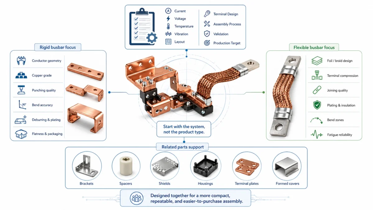
At JUMAI, we approach the rigid-versus-flexible question as an engineering and commercial decision. We do not start by forcing one product type. We start by understanding the system: current, voltage, temperature, vibration, layout, terminal design, assembly process, validation requirement, and production target.
For rigid busbars, we focus on conductor geometry, copper grade, punching quality, bend accuracy, deburring, plating, insulation windows, flatness, and packaging protection. Our experience with rigid busbar and cable comparison also helps buyers understand when a formed copper conductor can replace less organized cable routing in high-current cabinets.
For flexible busbars, we focus on structure, copper foil or braid design, terminal compression, joining quality, plating, insulation, bend zones, and fatigue reliability. Our flexible copper busbar sourcing guide and custom flexible copper busbar ordering strategy are useful references for procurement teams that need to control cost and risk when ordering online.
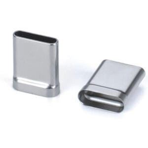
For projects that require related parts, we can also support precision stamped components, deep-drawn components, tooling, and accessories. That matters because a busbar may need brackets, spacers, shields, housings, terminal plates, or formed covers. When these parts are designed independently, the assembly may become harder than necessary. When they are designed together, the result is usually more compact, more repeatable, and easier to purchase.
Final recommendation: which solution is better?
For most fixed, compact, high-current distribution paths, Rigid Busbars are usually the better starting point. They offer clean routing, repeatable assembly, strong thermal predictability, efficient use of space, and easier inspection. They are especially strong in switchgear, UPS cabinets, power distribution units, inverter cabinets, industrial control equipment, and other systems where terminals are fixed and the current path should be orderly.
For systems exposed to vibration, movement, thermal expansion, tolerance stack-up, or repeated service movement, Flexible Busbars are usually the better starting point. They reduce mechanical stress, protect terminals, absorb misalignment, and improve reliability in dynamic environments. They are especially useful in EV battery packs, BESS modules, wind power equipment, generator connections, motor connections, railway applications, and other systems where a rigid conductor could transfer stress into the joint.
For many modern high-current systems, the best answer is not either-or. It is a hybrid architecture: rigid where the design needs precision and compactness, flexible where the design needs movement tolerance and stress relief.
If you are deciding between Rigid Busbars and Flexible Busbars, the safest next step is to send your drawing, 3D model, current profile, voltage requirement, installation environment, and production target to JUMAI for an engineering review. We can help evaluate whether your system should use rigid copper, flexible copper, braided copper, laminated construction, or a hybrid busbar design. The goal is not simply to make a conductor. The goal is to build a high-current connection that fits your product, protects your system, supports validation, and improves long-term commercial performance.