Modern electrical equipment is becoming smaller, denser, hotter, and more demanding. Electric vehicle battery packs must carry high current through compact module spaces. Battery energy storage systems need repeatable, low-resistance connections that can survive outdoor cabinets and long operating cycles. AI server racks and data center power shelves are pushing higher power density into spaces where traditional cable routing becomes difficult to assemble, inspect, and service. Renewable energy inverters, switchgear, charging systems, industrial drives, and high-current electronics all face the same basic question: how can power be moved safely, efficiently, and repeatably inside a real mechanical package?
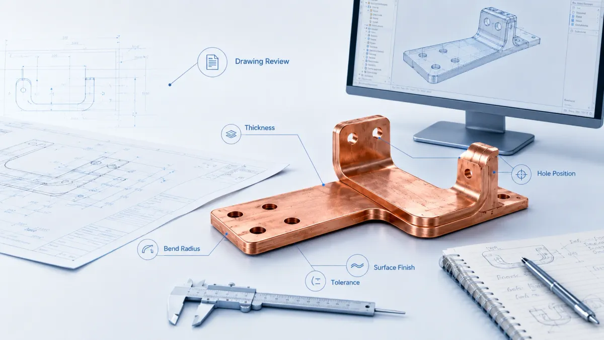
That is where a custom busbar becomes more than a simple copper strip. A well-designed busbar is an electrical conductor, a mechanical structure, a heat path, an assembly reference, and sometimes an insulated safety component at the same time. The difference between a good custom busbar and an ordinary copper part is not only the copper grade. It is the review of the drawing, the interpretation of the current path, the bend sequence, the hole tolerance, the plating area, the insulation window, the contact surface, the burr direction, and the final inspection plan.
JUMAI focuses on custom copper busbars for global customers that need soft, rigid, braided, laminated flexible, plated, and insulated copper conductors. The company also supports related precision metal parts, including deep drawn components, stamping dies, tooling, terminals, spacers, covers, and other custom hardware when a power assembly requires more than one conductive part. This article explains how a custom busbar project moves from drawing review to final copper part, and how buyers can prepare a stronger RFQ so that engineering review, quotation, sampling, and production can proceed with fewer delays.
The goal is not to make every buyer an electrical designer. The goal is to show what experienced busbar manufacturers look for when they receive a 2D drawing, 3D model, current requirement, or sample part. If the buyer understands the review logic, the project can avoid avoidable redesign, wrong plating, insulation interference, excessive tooling cost, and late-stage assembly problems.
- Why custom busbar manufacturing matters now
- What a custom busbar really includes
- How buyers should think about busbar type selection
- Drawing review: the first real manufacturing step
- What JUMAI checks during DFM review
- Material selection: why C11000/T2 copper is common, but not the only decision
- Electrical design: current, heat, and voltage drop are connected
- Mechanical design: holes, bends, flatness, and assembly stress
- Surface finish: bare copper, tin, nickel, and silver
- Insulation design: safety, fit, and manufacturability
- From drawing to final copper part: a practical manufacturing flow
- Quality control: what should be measured before shipment
- Cost drivers in custom busbar manufacturing
- Prototype, pilot run, and mass production: why each stage is different
- Application examples: EV, BESS, data centers, and power distribution
- What to send with a custom busbar RFQ
- Why work with a manufacturer that understands both copper busbars and precision metal forming
- Common mistakes that delay custom busbar projects
- How JUMAI supports global custom busbar buyers
- Final thoughts: better drawings create better copper parts
Why custom busbar manufacturing matters now
The demand for better current conductors is being pulled by several high-growth industries. Electric vehicles are a clear example. The International Energy Agency reported in its Global EV Outlook 2026 that global electric car sales grew by 20% in 2025 and exceeded 20 million units, equal to about one quarter of all new cars sold. Each EV contains many conductive links: module-to-module connections, pack-level interconnects, high-voltage junctions, inverter terminals, charging paths, and power electronics connections. These parts are not all identical, but many of them depend on copper conductors that must balance ampacity, vibration resistance, temperature rise, insulation, and packaging space.
Energy storage is another driver. The IEA’s Batteries and Secure Energy Transitions report highlights the role of batteries in power-sector storage, EVs, behind-the-meter systems, mini-grids, and renewable integration. Battery cabinets and containerized BESS systems often use rigid copper bars for stable high-current paths, laminated flexible copper busbars for compact connections, and braided connectors where vibration, tolerance variation, or thermal expansion must be absorbed.
Data centers are also changing the busbar conversation. The IEA estimates that data center electricity consumption was about 415 TWh in 2024, around 1.5% of global electricity consumption, and notes that it has grown at about 12% per year over the previous five years in its Energy and AI analysis. The same source projects data center electricity consumption to reach around 945 TWh by 2030 in its base case. Another IEA summary, Key Questions on Energy and AI, projects data center electricity consumption roughly doubling from 485 TWh in 2025 to 950 TWh in 2030. For hardware designers, this means power distribution inside racks, shelves, UPS cabinets, and power distribution units must become more compact and more thermally predictable. JUMAI’s article on bus bars for server rack power distribution is a useful internal reference for buyers working in data center applications.
In power distribution equipment, copper busbars have been used for decades. What has changed is the required precision. More customers now ask for controlled burr direction, defined plating thickness, selective insulation, laser marking, PPAP-style documentation, material traceability, and fast prototype iteration. A simple rectangular bar can still be appropriate in many systems, but a high-density EV pack or AI server rack often requires a custom geometry that fits the exact assembly sequence.
What a custom busbar really includes
A custom busbar is any busbar manufactured to a project-specific drawing, model, electrical requirement, or assembly condition. It can be a flat rigid copper bar with holes. It can also be a 3D CNC-bent conductor, a laminated flexible copper foil stack, a braided copper connector with pressed terminals, a tin-plated battery interconnect, a nickel-plated high-temperature part, a silver-plated contact region, or an insulated busbar with exposed windows only at the mounting points.
In practice, custom busbar manufacturing usually includes six decision areas.
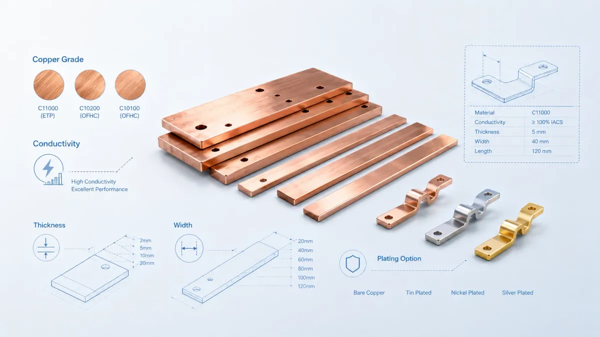
First, the conductor material must be selected. Many high-current busbars use C11000 or T2 copper because it offers high electrical conductivity and good formability. The Copper Development Association lists C11000 as a high-conductivity copper with a minimum copper content of 99.90% and a minimum conductivity of 100% IACS in the annealed condition on its C11000 alloy page. JUMAI’s Custom Copper Busbars page also describes the use of high-purity T2/C11000 copper for high-conductivity busbar manufacturing.
Second, the busbar structure must match the operating condition. Rigid busbars are strong, stable, and efficient for fixed geometry. Braided busbars absorb vibration and movement. Laminated flexible busbars use multiple thin copper foils to allow bending in tight spaces while keeping low-resistance current paths. For a deeper comparison, JUMAI’s copper busbar guide explains material, type, manufacturing, and customization options, while the flexible copper busbar guide for EV batteries, BESS, and power distribution focuses on flexible structures.
Third, the surface finish must be defined. Bare copper can work in controlled environments, but many production designs require tin plating for oxidation resistance, nickel plating for harsher thermal or environmental conditions, or silver plating at critical contact areas. The finish should not be described only as “plated.” A manufacturing drawing should state the plating material, thickness range, masking requirements, exposed copper restrictions, and whether the whole part or only selected contact regions must be plated.
Fourth, insulation must be coordinated with voltage, clearance, creepage, heat, and assembly. PVC dipping, powder coating, epoxy coating, PET insulation films, heat-shrink sleeves, and molded covers all behave differently. Insulation must not block the contact surface, reduce bolt seating area, crack at bends, or create a hidden interference with nearby components. If flame-retardant polymer insulation is required, buyers often specify UL 94 V-0 materials; UL describes UL 94 V-0, V-1, and V-2 as part of its combustion fire tests for plastics.
Fifth, the part must be manufacturable. A busbar drawing can be electrically correct and still be difficult to produce. Small hole-to-edge distances, impossible bend sequences, narrow slots near bend lines, sharp internal corners, unrealistic flatness requirements, unclear datum schemes, and unspecified burr direction can increase cost or cause unstable production. This is why drawing review is not a paperwork step. It is the point where manufacturing risk is found early.
Sixth, the final part must be inspectable. A supplier cannot control what is not defined. Critical dimensions, hole positions, plating thickness, insulation coverage, exposed windows, bend angle, flatness, burr limits, thread quality, and packaging requirements should be measurable. Good busbar manufacturing converts the drawing into a stable process and a practical inspection plan.
How buyers should think about busbar type selection
Choosing between rigid, flexible, braided, and laminated copper busbars should start with the assembly environment. A buyer may prefer one type because it looks simpler, but the final choice should be based on current, voltage, movement, installation tolerance, thermal expansion, vibration, available space, production volume, and service requirements.
| Buyer requirement | Common busbar choice | Engineering reason | RFQ note to provide |
|---|---|---|---|
| Fixed high-current path in a cabinet, inverter, switchgear, or power distribution unit | Rigid copper busbar | Strong structure, low voltage drop, easy inspection, stable bolted contact | Provide current, duty cycle, ambient temperature, mounting hole pattern, enclosure condition, and required plating |
| Battery module or pack connection with tight space and moderate movement | Laminated flexible copper busbar | Multiple copper foils allow controlled bending and compact routing | Provide bend direction, bending area, stack height limit, insulation window, and assembly sequence |
| High-vibration connection in EV, railway, industrial machinery, or moving equipment | Braided copper busbar | Woven copper strands absorb vibration, misalignment, and repeated mechanical stress | Provide vibration condition, terminal style, braid length, terminal thickness, and whether tinned braid is needed |
| Connection exposed to thermal expansion or tolerance mismatch | Flexible or braided copper busbar | Reduces stress on terminals and battery posts compared with a fully rigid conductor | Provide expected movement, module tolerance, temperature range, and required life cycle |
| High-reliability contact area with frequent assembly or higher corrosion risk | Plated rigid or flexible copper busbar | Tin, nickel, or silver plating can improve oxidation resistance or contact performance | Define plating material, thickness, salt spray or environmental expectation, and masked areas |
| High-voltage battery or power cabinet where touch protection is needed | Insulated copper busbar | Insulation reduces accidental contact risk and supports safer routing | Provide voltage class, creepage and clearance targets, exposed window drawing, and insulation material preference |
This table is a starting point, not a substitute for design validation. For example, a rigid busbar can work well in an EV battery pack if the mounting points are stable and the pack design controls vibration. A laminated flexible busbar can be useful in a data center power shelf if space is tight and assembly needs controlled bending. The right design depends on the whole assembly, not only the industry name.
For battery-specific projects, JUMAI’s Battery Busbar Design Guide for EV Battery Packs and Energy Storage Systems is a useful internal reference because it discusses the relationship between movement, current, voltage, packaging, cost, and production method.
Drawing review: the first real manufacturing step
A custom busbar project usually begins with a drawing, CAD file, sample, or concept. Buyers sometimes treat this as a quotation request only: send the file, receive a price, choose a supplier. That approach can work for simple flat copper bars, but it is risky for production busbars used in battery packs, power cabinets, and data center power distribution. A serious manufacturer reviews the drawing before quoting because the drawing controls cost, process stability, and delivery risk.
The first review area is the electrical requirement. The drawing may show thickness, width, and hole positions, but it may not explain continuous current, peak current, pulse duration, operating temperature, ambient temperature, airflow, enclosure condition, or allowable temperature rise. Busbar ampacity is not a fixed number determined only by cross-sectional area. The Copper Development Association’s busbar ampacity tables are calculated for rectangular Copper No. 110 busbars using a nominal conductivity of 99% IACS and provide values for temperature rises of 30, 50, and 65°C above ambient. This is useful as a reference, but actual equipment ratings still depend on installation, orientation, ventilation, spacing, enclosure heat, contact resistance, and system-level validation.
The second review area is the contact interface. A busbar is only as reliable as its joints. Engineers check hole size, slot size, bolt diameter, washer clearance, contact face flatness, plating coverage, burr direction, and whether insulation or coating could creep into the contact zone. A beautiful copper body with a poor contact face can still overheat at the joint.
The third review area is mechanical fit. Busbars often connect components that have their own tolerances: battery cells, modules, fuse holders, contactors, PCB terminals, breakers, terminal blocks, and enclosure studs. If the busbar drawing assumes perfect alignment, assembly may require force. That can create terminal stress, hidden cracks in insulation, thread damage, or inconsistent contact pressure. Flexible and braided busbars are often used not because they carry current better than rigid copper, but because they reduce mechanical stress when real parts are assembled.
The fourth review area is bend feasibility. Copper can be bent precisely, but bend radius, grain direction, material temper, thickness, hole location, bend-to-edge distance, and tooling access all matter. A hole too close to a bend line may distort. A narrow slot near a formed area can tear. A complex 3D bend may require a specific bend sequence. If the drawing does not show bend direction or datum references clearly, inspection disputes may happen later.
The fifth review area is finish and insulation. A plating note such as “tin plated” is not enough for a production-quality drawing. The manufacturer needs plating thickness, measurement area, whether threads are plated, whether the part is plated before or after forming, whether masking is required, and how cosmetic defects should be judged. For insulation, engineers need coating thickness, exposed copper windows, edge coverage, pinhole requirements, flame-retardant grade, and whether insulation must be tested by dielectric withstand or other methods.
The sixth review area is documentation. Some projects require only a commercial invoice and dimensional report. Others need material certificates, RoHS/REACH declarations, plating reports, PPAP-style documentation, process flow diagrams, control plans, IMDS input, salt spray reports, or insulation test records. Buyers should state documentation expectations early because they influence lead time, cost, and supplier selection.
What JUMAI checks during DFM review
DFM, or design for manufacturability, is where the supplier converts the customer’s design intent into a stable manufacturing plan. The table below summarizes common review points for custom busbar projects.
| Review area | What engineers check | Common risk if ignored | Buyer can provide |
|---|---|---|---|
| Material grade and temper | C11000/T2 grade, hardness, formability, conductivity, material certificate needs | Cracking during bending, lower-than-expected conductivity, inconsistent springback | Material standard, conductivity requirement, hardness range, certificate format |
| Cross-section and current path | Width, thickness, neck-down regions, slots, hole interruptions, continuous and peak current | Local heating, voltage drop, overdesign, unnecessary copper cost | Current profile, duty cycle, temperature rise target, installation environment |
| Bend geometry | Bend radius, bend angle, sequence, grain direction, hole distance from bend | Distorted holes, cracks, unstable angle, tool interference | 3D model, flat pattern if available, allowable bend tolerance, critical surfaces |
| Contact interface | Hole size, slot size, flatness, burr direction, plating at contact region | High contact resistance, hot spots, assembly torque variation | Bolt size, washer size, torque target, mating material, contact area requirement |
| Plating and surface finish | Tin, nickel, silver, bare copper, thickness, masking, cosmetic standard | Oxidation, poor solderability, unnecessary cost, rejected appearance | Plating specification, corrosion requirement, exposed/masked areas, sample standard |
| Insulation | Coating material, coverage, exposed windows, thickness, flame rating, dielectric expectation | Coating in contact zone, cracks at bend, creepage risk, fit interference | Voltage class, creepage/clearance target, insulation drawing, test requirement |
| Inspection | Critical dimensions, datum scheme, gauges, sampling level, report format | Disputes after delivery, over-inspection cost, missed critical features | CTQ list, assembly drawing, inspection report template, approval process |
A useful DFM review does not simply say yes or no. It should identify what must remain fixed and what can be optimized. For example, a battery module hole pattern may be fixed because it matches cell terminals. But an outer contour, bend radius, slot length, or insulation edge may be adjustable. A small change may reduce scrap, improve assembly, or avoid a special tool.
This is where JUMAI’s manufacturing mix is valuable. A project may require rigid busbars, laminated flexible busbars, braided copper connectors, stamped terminals, deep drawn shields, or small brackets in the same assembly. When a supplier understands both copper busbars and related precision metal forming, it can often suggest a more practical assembly solution rather than quoting each part in isolation.
Material selection: why C11000/T2 copper is common, but not the only decision
Copper is preferred for many high-current busbars because it combines high electrical conductivity, high thermal conductivity, good corrosion resistance, and good formability. C11000/T2 copper is common because it is commercially pure and well understood in busbar manufacturing. The Copper Development Association’s C11000 data shows minimum copper content of 99.90% and minimum conductivity of 100% IACS in the annealed condition. The CDA also notes in its broader guide to working with copper and copper alloys that commercially pure copper has about 101% IACS conductivity, while some copper alloys trade conductivity for strength or other properties.
For buyers, the practical lesson is simple: do not choose material only by price. A cheaper or stronger copper alloy may not carry current with the same efficiency as high-conductivity copper. A very soft copper may form easily but may not hold a threaded feature or contact pressure as expected. A harder temper may improve mechanical stability but increase bending difficulty. The right material is a balance between conductivity, formability, strength, plating compatibility, cost, and availability.
The material decision also affects bend design. Annealed copper bends more easily but may deform during handling. Harder copper can maintain shape but may need larger bend radii and better control of grain direction. Thin copper foils for laminated flexible busbars behave differently from thick rigid bars. Braided copper uses many strands, so its current path, flexibility, and terminal pressing method are different from a solid bar.
Buyers should also consider whether the busbar will be welded, soldered, bolted, pressed, or mechanically clamped. Oxygen-containing copper grades can have limitations in certain welding or high-temperature reducing environments. If the project uses special joining processes, this should be disclosed at RFQ stage.
A strong RFQ should state the material grade if known, or at least the performance requirement if the grade is not fixed. For example, “C11000 copper, tin plated, conductivity ≥ 99% IACS, material certificate required” is much clearer than “red copper busbar.” If the buyer is not sure, JUMAI can review the application and recommend a material direction based on current, forming, plating, and assembly needs.
Electrical design: current, heat, and voltage drop are connected
Many buyers ask, “How many amps can this copper busbar carry?” The honest answer is that ampacity depends on more than size. Cross-sectional area is important, but current carrying capacity also depends on ambient temperature, allowable temperature rise, busbar surface area, orientation, airflow, enclosure condition, adjacent heat sources, plating, insulation, spacing, and contact resistance.
A flat copper bar in open air can dissipate heat differently from the same bar inside a sealed battery pack. A vertical busbar may cool differently from a horizontal one. An insulated busbar may retain more heat than a bare one. A busbar with multiple holes, slots, or narrow sections may have localized current density increases. A bolted joint with inadequate contact pressure can become the hottest point even when the copper body is large enough.
Voltage drop is another practical issue. In a high-current system, a small resistance can create meaningful power loss. Power loss follows the familiar I²R relationship: when current doubles, resistive heating increases four times if resistance remains the same. This is why contact resistance, surface finish, bolt torque, and plating condition matter so much in EV packs, BESS cabinets, switchgear, and rack-level power distribution.
During drawing review, engineers look for neck-down sections. A slot, fuse opening, bend relief, or mounting hole may reduce the effective conductor width. If current must pass through that narrow area continuously, the local temperature may rise. For this reason, the minimum cross-section along the actual current path matters more than the largest width shown on the drawing.
For preliminary sizing, engineers may compare the proposed geometry against internal experience, CDA busbar tables, thermal calculations, customer requirements, and similar tested parts. For final validation, the customer or system integrator should verify the design in the actual equipment environment. This is especially important for battery systems, high-voltage power cabinets, and safety-critical assemblies.
Mechanical design: holes, bends, flatness, and assembly stress
A custom busbar must fit the real assembly, not only the CAD model. Mechanical design errors often appear late because the copper part may look correct by itself. Problems become obvious only when it is bolted to a module, contactor, breaker, PCB terminal, or enclosure.
Hole design is one of the most common issues. Round holes are simple, but slots may be needed when the assembly has tolerance variation. However, slots reduce contact area and may affect current density if placed in the current path. Hole-to-edge distance must be sufficient to prevent tearing, deformation, or weak contact zones. If a threaded hole is required, the copper thickness may not be enough for thread engagement, and a PEM nut, rivet nut, welded nut, or other insert may be more reliable.
Bend design is another frequent challenge. A 3D busbar may require multiple bends in different planes. The bend order must allow tooling access. Holes near bend lines may distort unless the process is designed carefully. Tight bends can crack, especially with harder material or unfavorable grain direction. In some cases, increasing bend radius slightly can improve production stability without affecting assembly performance.
Flatness and coplanarity should be specified only where they matter. Overly tight flatness across a long copper part can increase cost because copper is ductile and can move during cutting, punching, bending, plating, and heat-related processes. It is better to define the critical contact surfaces and allow reasonable tolerance on non-critical areas.
Assembly stress is especially important in battery systems and high-vibration equipment. If a rigid busbar connects two points that move relative to each other, the copper may transfer stress into terminals. Over time, that can loosen fasteners, damage coatings, or fatigue the conductor. This is where flexible laminated busbars and braided connectors can protect the assembly. They act as electrical conductors and mechanical stress relief components at the same time.
The buyer should provide the assembly drawing whenever possible. A busbar drawing alone shows the part. An assembly drawing shows what the part must survive. This helps the manufacturer identify whether the current design is too rigid, too flexible, too difficult to install, or too sensitive to tolerance stack-up.
Surface finish: bare copper, tin, nickel, and silver
Surface finish is not cosmetic only. It affects oxidation resistance, contact behavior, solderability, environmental durability, and sometimes cost more than buyers expect.
Bare copper offers excellent conductivity but oxidizes in air. In some controlled environments, bare copper is acceptable, especially when contact pressure is reliable and oxidation is managed. But for many production assemblies, plating is preferred.
Tin plating is widely used for copper busbars because it provides practical oxidation resistance and is generally cost-effective. It is common in power distribution, battery systems, industrial equipment, and many electrical assemblies. Tin plating can also support solderability in some designs, although soldering requirements should be stated clearly.
Nickel plating is often selected for harsher environments, higher temperatures, or applications where improved wear and corrosion resistance are needed. Nickel is not chosen mainly because it is more conductive than copper; it is chosen because it can protect the contact surface under more demanding conditions.
Silver plating is typically used for high-performance contact areas where low contact resistance and high reliability are important. Because silver plating is more expensive, it is often applied selectively rather than across the whole part.
A good busbar drawing should define plating in practical manufacturing language. The note should include plating type, thickness range, measurement location, whether plating is required before or after forming, masked areas, contact windows, threads, cosmetic criteria, and corrosion test requirements if any. If the customer only writes “Sn plated,” the manufacturer must guess the thickness and acceptance standard. That creates quotation uncertainty and possible quality disputes.
Insulation design: safety, fit, and manufacturability
Insulated busbars are common in EV batteries, BESS cabinets, power electronics, switchgear, and data center power modules. Insulation can reduce accidental contact risk, support compact routing, and help separate positive and negative conductors. But insulation is not simply a coating applied at the end. It must be designed into the part.
The first insulation question is voltage. Higher voltage usually requires more attention to creepage, clearance, dielectric performance, exposed conductor windows, and contamination risk. For low-voltage switchgear assemblies, the IEC 61439 family of standards is often referenced in the industry; the IECEE page for IEC 61439-2:2020 identifies it as a standard for low-voltage switchgear and controlgear assemblies. The busbar itself may be only one component in a larger assembly, but the design team must still consider the system-level safety requirements.
The second question is material. PVC dipping, epoxy coating, powder coating, PET film, heat-shrink tube, and molded insulation covers all have different thickness, flexibility, heat resistance, edge coverage, and cost. For some projects, a UL 94 V-0 flame-retardant material is requested. For others, dielectric strength, abrasion resistance, or dimensional stability may be more important.
The third question is exposed copper windows. A busbar normally needs exposed contact areas for bolting, welding, or electrical connection. These exposed areas must be large enough for washers, terminals, plating measurement, and assembly tolerance. If the insulation opening is too small, it may interfere with contact pressure. If it is too large, the design may lose safety margin or create unnecessary exposed conductor.
The fourth question is bend behavior. If insulation is applied before bending, it may crack, wrinkle, or thin at formed areas. If insulation is applied after bending, masking and thickness control may be harder. Laminated flexible busbars may need insulation films arranged so that the bending zone remains flexible while contact pads remain exposed.
The fifth question is inspection. Insulation thickness, coverage, pinholes, adhesion, dielectric withstand, and visual defects should be defined if they are critical. For high-volume projects, a clear insulation inspection standard avoids subjective approval based only on appearance.
From drawing to final copper part: a practical manufacturing flow
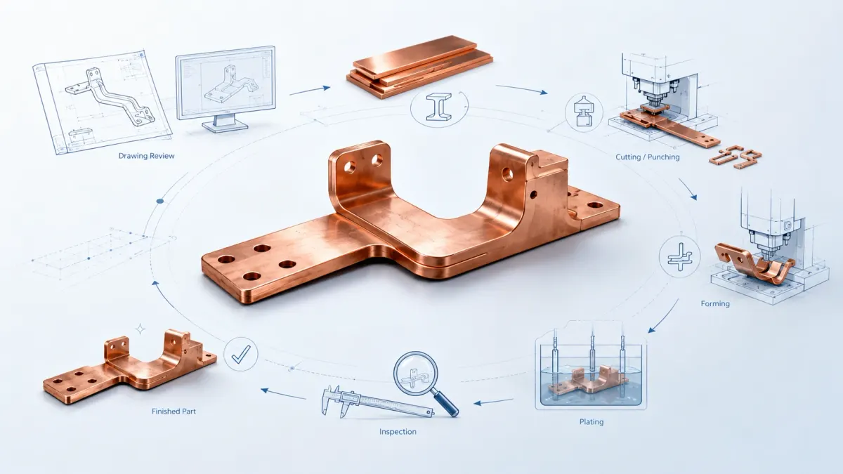
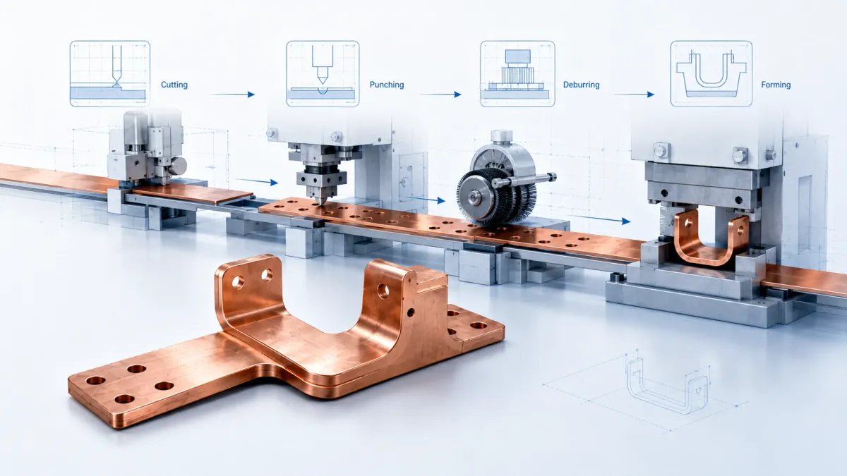
The exact process depends on busbar type, volume, and specification, but many custom busbar projects follow a similar route. The table below shows a practical flow from RFQ to shipment.
| Manufacturing stage | Main output | Inspection or decision point | Buyer value |
|---|---|---|---|
| RFQ and drawing review | Feasibility comments, missing information list, quotation basis | Check material, current, finish, insulation, tolerance, volume, documentation | Reduces quotation errors and exposes design risk early |
| DFM optimization | Updated drawing suggestions or confirmed manufacturing plan | Confirm bend radius, hole position, plating areas, insulation windows, critical dimensions | Improves manufacturability before tooling or sampling cost is committed |
| Prototype or first article | Physical sample or small batch | Dimensional inspection, fit check, contact review, coating/plating confirmation | Lets buyer test assembly before mass production |
| Process confirmation | Production route, tooling, fixture, control plan | Confirm cutting, punching, bending, welding, pressing, plating, coating, marking | Creates repeatability for production parts |
| Mass production | Finished copper busbars | In-process inspection, final dimensional report, surface finish review, electrical/insulation tests if required | Provides stable supply for assembly line needs |
| Packaging and shipment | Protected parts ready for receiving inspection | Check oxidation protection, contact surface protection, label, batch traceability | Reduces damage, mixing, and receiving delays |
For rigid busbars, production may include material cutting, CNC punching, laser cutting, deburring, bending, tapping, cleaning, plating, insulation, marking, final inspection, and packaging. For laminated flexible busbars, the process may include foil preparation, stacking, diffusion welding or press welding at terminal areas, forming, trimming, plating, insulation film application, and inspection. For braided busbars, production may include braid preparation, terminal forming, cold pressing, solder dipping if specified, plating, shaping, and pull or visual inspection depending on project requirements.
At JUMAI, the manufacturing route is selected according to geometry, current, quantity, finish, and application. The company’s product page describes capabilities such as precision punching, CNC bending, cold pressing for braided terminals, diffusion welding for laminated flexible busbars, plating, and insulation. The value for buyers is not only that these processes exist, but that they are reviewed together before production begins.
Quality control: what should be measured before shipment
Quality control for a custom busbar should match the failure risk. Not every dimension needs the same inspection intensity. A non-critical outer contour may allow more tolerance, while a hole position, contact flatness, or exposed insulation window may need tighter control.
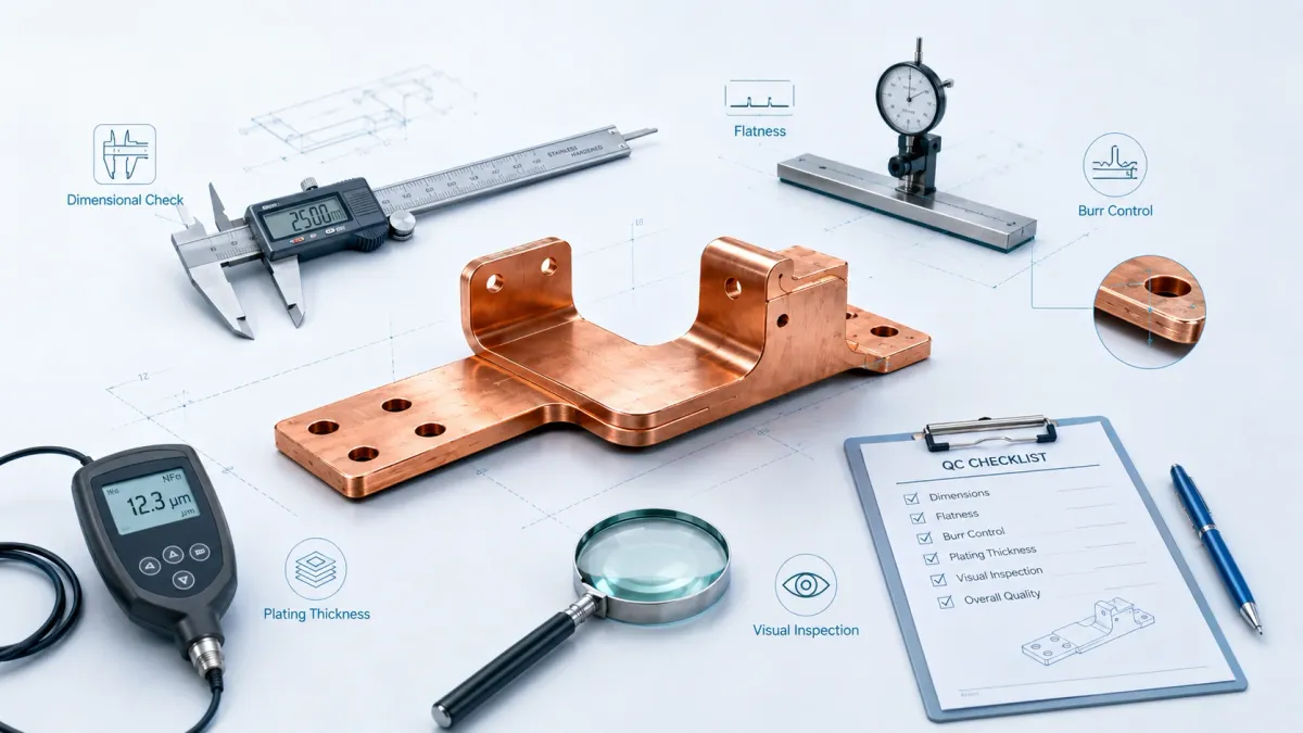
Dimensional inspection normally includes overall length, width, thickness, hole diameter, slot size, hole position, bend angle, bend height, flatness of contact areas, and critical distances between mounting points. For 3D busbars, inspection fixtures may be useful because standard calipers cannot always confirm the assembled geometry efficiently.
Surface inspection includes burrs, scratches, dents, oxidation, plating defects, discoloration, exposed copper, and cosmetic limits. For busbars, burr direction is important because a burr on the contact surface can affect contact resistance or damage insulation. Burrs near assembly workers can also create handling safety issues.
Plating inspection may include thickness measurement, adhesion checks, visual inspection, and corrosion-related tests if specified. Plating thickness should be measured at defined locations because edges, holes, and recesses may plate differently from flat surfaces.
Insulation inspection may include coating thickness, exposed window size, adhesion, dielectric testing, pinhole inspection, and visual coverage. The test method should match the application. A low-voltage insulated copper link may not need the same test as a high-voltage battery busbar.
Functional or assembly inspection may include gauge fitting, thread checks, terminal pull checks for braided connectors, or sample fit checks against mating hardware. For production orders, packaging inspection is also important. Contact surfaces should be protected from scratches and contamination. Parts should not rub against each other in transit if plating or insulation can be damaged.
A good supplier does not inspect quality only at the end. It controls quality through material sourcing, tooling, process setup, first article approval, in-process checks, and final inspection. For buyers, this means the RFQ should state which dimensions and features are critical. If everything is marked critical, cost increases. If nothing is marked critical, the supplier may not know where the real risk is.
Cost drivers in custom busbar manufacturing
A custom busbar price is not just copper weight multiplied by a material price. Copper cost matters, but the final part price also depends on process complexity, tolerance, finish, insulation, documentation, packaging, and order volume.
Material utilization is a major factor. A simple rectangular bar has high material yield. A complex contour with large cutouts may generate more scrap. A thick copper part with many holes may require more punching force or slower machining. A laminated flexible busbar may use multiple foils, terminal welding, and insulation steps.
Tooling and fixture cost also matter. Prototype quantities can often be made with flexible processes such as laser cutting, CNC bending, and manual inspection. Higher-volume production may justify dedicated punching tools, bending fixtures, welding fixtures, inspection gauges, or automated coating masks. Tooling increases upfront cost but can reduce unit cost and improve repeatability.
Tolerance drives cost. Tight tolerances require better tooling, more inspection, and sometimes slower production. Buyers should avoid applying tight tolerances to non-critical features. A clear datum scheme and CTQ list often reduce cost because the manufacturer can focus control where it matters.
Plating and insulation can be significant cost drivers. Selective plating may save material cost but increase masking complexity. Full plating may be easier but more expensive if silver or nickel is specified. Insulation with precise exposed windows may require custom masks or fixtures. Dielectric testing, flame-retardant documentation, or cosmetic standards may add time.
Documentation requirements can also affect price. A simple commercial order may need basic inspection records. Automotive, energy storage, or safety-related projects may require material certificates, plating reports, process flow charts, control plans, PPAP documentation, traceability labels, or special packaging records. These requirements are valuable, but they should be included in the RFQ so that cost and lead time are realistic.
Prototype, pilot run, and mass production: why each stage is different
A prototype busbar proves geometry and basic function. It answers questions such as: does the part fit, do the holes align, does the bend clear the enclosure, does the insulation window expose the correct contact area, and can the assembly worker install it without force? Prototype parts may be made with slower and more flexible methods.
A pilot run proves process repeatability. It tests whether the supplier can make not one good part, but many consistent parts. Pilot production may reveal issues that prototypes do not show, such as coating variation, bend springback, plating buildup in holes, packaging scratches, or inspection time. This stage is especially important when the project will later move to mass production.
Mass production requires process control. The question is no longer only “can this part be made?” The question becomes “can this part be made repeatedly, inspected efficiently, packed safely, and delivered on schedule?” Tooling, fixtures, operator instructions, inspection gauges, batch control, and supplier communication become more important.
Buyers should avoid approving a prototype without testing the real assembly condition. A busbar sample may pass dimensional inspection but fail because the mating component has tolerance variation. It may fit at room temperature but create stress after thermal cycling. It may look good before plating but have contact issues after coating. The more the prototype test reflects the real operating environment, the fewer problems appear later.
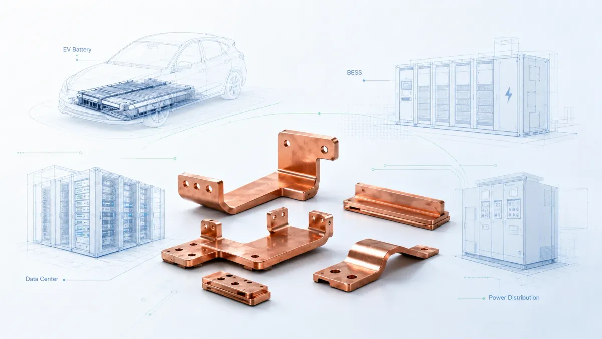
Application examples: EV, BESS, data centers, and power distribution
In EV battery packs, busbars connect cells, modules, fuses, contactors, current sensors, and pack terminals. The design must consider vibration, thermal expansion, service safety, insulation, and compact routing. Rigid busbars can provide stable low-resistance paths, while flexible laminated busbars and braided connectors help absorb movement. Plating and insulation are often critical because contact reliability and safety are both important.
In BESS cabinets, busbars may connect battery racks, DC combiner sections, fuse holders, switch-disconnectors, power conversion systems, and grounding paths. These systems may operate outdoors or in containerized environments. Buyers should consider corrosion resistance, temperature range, maintenance access, and clear labeling. Insulated copper busbars are common where compact high-current routing must remain safe for installation and service.
In data centers, power density and uptime pressure make busbar design increasingly important. Server rack power distribution may require compact conductors that are easier to assemble and more organized than cable bundles. JUMAI’s internal article on server rack bus bars explains why rack-level and cabinet-level conductors need careful design as AI servers increase power demand.
In switchgear and industrial power distribution, busbars must handle high current, short-circuit forces, temperature rise, and maintenance conditions. System-level design may reference standards such as IEC 61439, but the custom copper part still needs practical manufacturing control: hole accuracy, contact surface quality, plating, insulation, and reliable assembly.
In renewable energy equipment, inverters, combiner boxes, wind power converters, and charging infrastructure often need custom copper conductors that fit compact electrical layouts. The design may require tin plating, nickel plating, insulation, or heat dissipation features. For these applications, busbar manufacturing is closely connected to thermal management and service reliability.
What to send with a custom busbar RFQ
A strong RFQ saves time for both buyer and manufacturer. It does not need to be perfect, but it should include enough information to support a meaningful review.
At minimum, send the 2D drawing and 3D model if available. Common file formats include PDF, DXF, DWG, STEP, IGES, and CAD-native formats. The 2D drawing should include dimensions, tolerances, material, finish, insulation, critical features, and revision status. The 3D model helps confirm bend direction and assembly geometry.
Provide electrical requirements. State continuous current, peak current, duty cycle, voltage class, allowable temperature rise, ambient temperature, enclosure condition, and whether the part is in free air, inside a cabinet, inside a battery pack, or near heat-generating components. If the current requirement is not final, provide the expected range.
Provide mechanical information. Include mating components, bolt size, torque requirement, washer size, contact surface requirement, vibration condition, expected movement, and whether the busbar must compensate for tolerance. If the part connects battery modules or devices with positional variation, say so.
Provide surface finish and insulation expectations. State bare copper, tin plating, nickel plating, silver plating, selective plating, coating type, insulation material, exposed windows, color, flame rating, dielectric test, and cosmetic standard if applicable.
Provide quantity and project stage. A quote for 20 prototype pieces is different from a quote for 50,000 production pieces. State prototype quantity, annual volume, expected production schedule, and whether tooling investment is acceptable.
Provide documentation needs. If you require material certificates, RoHS, REACH, plating reports, dimensional reports, PPAP, IMDS, control plan, or special packaging labels, include that information early.
Finally, explain the application. A short sentence such as “rigid copper busbar for 800 V EV battery disconnect unit” or “tin-plated braided busbar for vibration compensation between inverter and module” helps engineers understand the design intent quickly.
Why work with a manufacturer that understands both copper busbars and precision metal forming
Some suppliers can cut copper. Fewer suppliers can review a high-current assembly from electrical, mechanical, surface treatment, insulation, tooling, and production perspectives. A custom busbar project often touches several disciplines at the same time. This is why supplier capability matters.
JUMAI manufactures soft, hard, braided, and laminated flexible copper busbars and supports surface finishes such as tin, nickel, silver, and custom insulation. The company also provides precision stamping, deep drawn components, stamping die customization, and tooling or mold components. This combination is useful when a buyer needs not only the busbar, but also related terminals, shields, brackets, covers, spacers, or formed metal components.
For example, an EV battery assembly may require a laminated flexible busbar, a stamped nickel-plated terminal, an insulating cover, and a small deep drawn shielding part. A data center power module may require rigid copper bars, formed brackets, plated contact pieces, and protective covers. A supplier with broader precision metal capability can help buyers reduce communication gaps between separate part suppliers.
This does not mean every project should be redesigned by the manufacturer. It means that early engineering review can identify risks before they become expensive. A supplier that understands bending, punching, plating, insulation, pressing, welding, and inspection can often suggest small changes that improve the final part without changing the customer’s electrical concept.
Common mistakes that delay custom busbar projects
One common mistake is sending only a picture. A photo can help explain the shape, but it cannot define tolerances, material, plating, or critical dimensions. If only a sample exists, the supplier may need reverse engineering, which takes time and may still require buyer approval of the final drawing.
Another mistake is using unclear material names. Terms such as “red copper,” “pure copper,” or “conductive copper” may mean different things to different teams. It is better to specify C11000/T2 copper, or state the required conductivity and certificate expectation.
A third mistake is ignoring the assembly environment. A busbar that works on a bench may fail in a vibrating vehicle, sealed cabinet, or high-temperature power module. The manufacturer should know whether the part is exposed to movement, heat, humidity, outdoor conditions, salt mist, or repeated maintenance.
A fourth mistake is over-tightening all tolerances. Tight tolerances are useful on critical features, but unnecessary tight tolerances increase cost and lead time. Buyers should mark critical-to-quality features and allow reasonable tolerance on non-critical contours.
A fifth mistake is treating insulation as an afterthought. Insulation changes thickness, bend behavior, fit, and contact windows. It should be designed and reviewed with the copper part, not added as a vague note after the mechanical design is frozen.
A sixth mistake is approving price before defining inspection. If the supplier quotes a simple part and later receives a demand for 100% inspection, plating reports, dielectric testing, and special packaging, the original price may no longer be realistic. Inspection and documentation should be part of the quotation basis.
How JUMAI supports global custom busbar buyers
JUMAI’s role is to help buyers turn a drawing or concept into a manufacturable copper part. The process usually begins with drawing evaluation. Engineers review material, geometry, bend feasibility, current path, finish, insulation, tolerance, and application. If information is missing, the team asks targeted questions rather than making silent assumptions.
After review, JUMAI can provide quotation, DFM comments, and prototype support. For suitable projects, samples allow the buyer to check assembly fit, contact areas, bend geometry, coating, and finish before approving production. This is especially valuable for EV, BESS, data center, and industrial power projects where late design changes are expensive.
For production, JUMAI can support cutting, punching, CNC bending, braided terminal pressing, laminated flexible busbar welding, plating, insulation, marking, inspection, and packaging according to the approved drawing and quality requirements. When related precision metal components are needed, the company’s deep drawing and tooling capability can support broader assembly needs.
Buyers can start from the Custom Copper Busbars page, review related technical articles in the JUMAI Knowledge Base, or send drawings through the contact page for engineering review. For projects involving precision formed metal accessories, the Deep Drawn Components page is also relevant.
Final thoughts: better drawings create better copper parts
Custom busbar manufacturing is not only a fabrication service. It is a translation process. The buyer’s electrical and mechanical requirements must be translated into copper grade, cross-section, bend geometry, hole pattern, contact surface, plating, insulation, tooling, inspection, and packaging. When that translation is done carefully, the final copper part is easier to assemble, easier to inspect, and more reliable in service.
The best time to improve a busbar is before production begins. A small change in bend radius, plating note, insulation window, hole tolerance, or contact surface requirement can prevent costly problems later. A clear RFQ helps the manufacturer quote accurately. A practical DFM review helps the buyer avoid design risk. A controlled prototype helps both sides confirm the part before mass production.
For EV batteries, BESS cabinets, renewable energy systems, data centers, switchgear, industrial equipment, and high-current electronics, the custom busbar is a small part with a large responsibility. It carries current, manages heat, connects hardware, and supports system reliability. If your project needs a rigid copper busbar, laminated flexible busbar, braided copper connector, plated copper part, or insulated high-current conductor, JUMAI can review your drawings and help move the project from design intent to final copper part.