Compact power systems are changing the way engineers and purchasing teams think about copper conductors. In older electrical cabinets, a designer could often leave more space between devices, route a large cable through a relaxed bend radius, or use a thick rigid copper bar with generous clearance. In modern equipment, that extra room is disappearing. EV battery packs are flatter. BESS racks are denser. Data center power shelves carry more current in less space. Solar inverters, UPS modules, charging cabinets, power distribution units, and industrial automation panels are all expected to become smaller, more modular, easier to assemble, and easier to maintain.
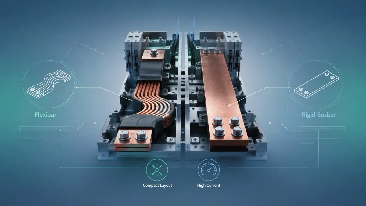
That is why the keyword flexibar is appearing more often in power distribution projects. A flexibar is not simply a soft version of a copper busbar. In practical engineering language, it usually refers to an insulated flexible copper bar made from stacked thin copper laminations that can be bent, folded, and twisted to fit short, compact, high-current connections. It often sits between two categories: it is more structured and space-efficient than a round cable, but more tolerant of installation offset and vibration than a traditional solid copper busbar.
For a manufacturer like JUMAI Custom Copper Busbars, this comparison is not theoretical. JUMAI manufactures hard/rigid copper busbars, laminated flexible copper busbars, and soft/braided copper busbars for new energy vehicles, renewable energy, power distribution, and data center applications. In many real projects, the best answer is not only flexibar or only rigid copper busbar. The best answer is the right conductor architecture for each current path.
This article compares flexibar and traditional copper busbar from a buyer-oriented point of view. It explains how each option performs in compact power systems, where each one creates risk, and what information you should prepare before requesting a custom quote.
- What Do Buyers Mean by Flexibar?
- What Is a Traditional Copper Busbar?
- Why Compact Power Systems Make This Decision More Important
- Flexibar vs Traditional Copper Busbar: Quick Comparison
- Electrical Performance: Current, Voltage Drop, and Heat
- Mechanical Fit: Where Flexibar Wins
- Where Traditional Copper Busbar Still Wins
- Space Efficiency: Shorter Path Is Not Always Better
- Thermal Management in Compact Enclosures
- Safety, Insulation, Creepage, and Clearance
- Assembly and Manufacturing Cost
- Application-by-Application Recommendation
- Flexibar in EV and BESS Power Systems
- Flexibar in Data Centers and High-Density Power Shelves
- Flexibar in Switchgear, Cabinets, and Industrial Equipment
- When Flexibar Is the Better Choice
- When Traditional Copper Busbar Is the Better Choice
- The Best Answer Is Often a Hybrid Busbar Assembly
- How to Specify a Custom Flexibar or Rigid Copper Busbar
- Manufacturing Details Buyers Should Not Ignore
- Quality Control: What a Serious Supplier Should Check
- Common Mistakes in Flexibar and Busbar Projects
- Why Work With JUMAI for Custom Flexibar and Copper Busbar Projects?
- FAQ: Flexibar vs Traditional Copper Busbar
- Final Recommendation
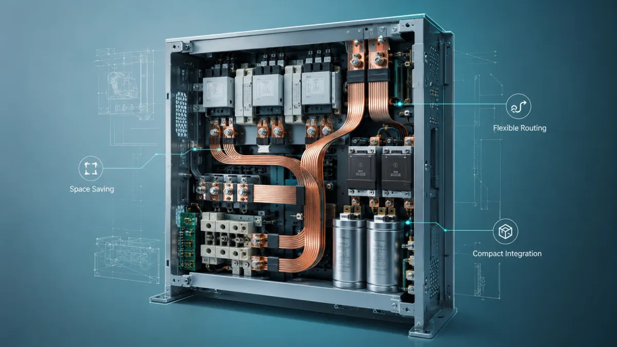
What Do Buyers Mean by Flexibar?
In the market, the word flexibar is often used in two ways. First, some buyers use it as a general term for an insulated flexible copper busbar. Second, some use it to describe a specific catalog-style flexible bar product used inside low-voltage switchboards, control panels, generators, transformers, busduct interfaces, and power distribution equipment.
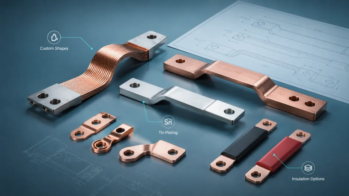
A typical flexibar is built from multiple thin copper strips stacked together. The strips are insulated as an assembly, while the terminal zones are prepared for bolted connections, punching, welding, or compression. Because the individual copper layers can slide slightly against each other during bending, the conductor can form tighter shapes than a thick solid bar of equivalent current capacity. This layered structure is the key reason flexibar can be routed through compact power compartments.
For example, commercial flexibar-style products available through nVent ERIFLEX distributors are described in ranges from about 19.5 mm2 to 1200 mm2 and 125 A to 2800 A, with some configurations using multiple conductors per phase for higher current. Helios Power Solutions also notes that such flexible bars can be bent, folded, or twisted for shorter and more compact connections, and may replace multiple round conductors in certain low-voltage applications (Helios Power Solutions – nVent ERIFLEX Flexibar). These figures should not be copied into a custom design without verification, but they show why the product category is attractive to engineers working in high-current but space-limited assemblies.
In JUMAI’s own technical language, the closest product family is the laminated flexible copper busbar. JUMAI explains in its article What Is a Flexible Busbar and Why Is It Used in High-Current Electrical Systems? that flexible busbars are part of a broader portfolio including rigid copper busbars, braided copper busbars, and laminated flexible busbars. The choice depends on current, voltage, heat, vibration, movement, insulation, and assembly conditions.
What Is a Traditional Copper Busbar?
A traditional copper busbar is a solid copper strip, bar, or plate used to collect and distribute current inside electrical equipment. It may be straight, punched, slotted, tapped, bent, plated, insulated, or assembled with spacers and supports. In high-current systems, rigid copper busbars are valued because their geometry is predictable. The cross-section is known. The hole positions are fixed. The connection surfaces can be controlled. The part can be inspected with simple dimensional tools. It can also provide mechanical stiffness in a power cabinet or battery enclosure.
The Copper Development Association lists C11000 copper as a high-conductivity copper with a minimum conductivity of 100% IACS in the annealed condition and a minimum copper content of 99.90% (Copper Development Association – C11000 Alloy). The same organization provides copper busbar ampacity tables based on Copper No. 110 with nominal 99% IACS conductivity and temperature rises of 30, 50, and 65 degrees C above ambient (Copper Development Association – Electrical Busbar). These references matter because they remind buyers that current rating is not a random catalog number. It depends on conductor material, cross-section, surface condition, temperature rise, enclosure condition, ventilation, and installation environment.
Traditional copper busbars remain widely used because they solve many engineering problems very well. A rigid bar can carry high continuous current with low voltage drop. It can be braced for short-circuit forces. It can be plated at the contact area. It can be formed into a repeatable shape for mass production. It can help create a clean, serviceable layout in switchgear, inverters, data center rack PDUs, and industrial control panels.
JUMAI discusses these design variables in more detail in its Copper Busbar Guide: Materials, Types, Manufacturing and Custom Options and its article on Copper Bus Bars for Power Distribution. Those guides are useful companion resources when the project is still at the concept stage.
Why Compact Power Systems Make This Decision More Important
Compact power systems are not just smaller versions of older systems. They usually operate with tighter thermal margins, shorter assembly time targets, stricter insulation requirements, and more difficult routing. The conductor is no longer a background component. It affects the entire product architecture.
In EV and energy storage systems, market growth is pushing power electronics and battery interconnect designs toward higher production volumes and more standardized assembly. The International Energy Agency reported that the electric car market exceeded 20 million sales in 2025, with electric cars reaching 25% of the overall car market that year (IEA Global EV Outlook 2026 – Trends in Electric Cars). This growth increases demand for reliable battery module interconnects, high-voltage distribution busbars, inverter links, charging connections, and energy storage rack conductors.
Data centers are following a similar density trend. The IEA projects global data center electricity consumption to more than double to around 945 TWh by 2030, with data center electricity consumption growing around 15% per year from 2024 to 2030 in its Base Case (IEA Energy and AI – Energy Demand from AI). It also notes that AI is a major driver of this growth and that data center electricity demand becomes increasingly important in local power markets (IEA Energy and AI – Executive Summary). For power distribution designers, this means higher currents, denser racks, more thermal constraints, and a stronger need for compact, repeatable conductor systems.
These market trends do not automatically mean flexibar is better than a rigid copper busbar. They mean the selection must be more deliberate. The right conductor needs to satisfy electrical performance, mechanical fit, insulation safety, thermal management, manufacturability, serviceability, and cost control at the same time.
Flexibar vs Traditional Copper Busbar: Quick Comparison
The table below gives a practical first-level comparison. It is intentionally simple. A final design should still be verified by engineering calculation, prototype testing, temperature-rise evaluation, insulation checks, and application-specific standards review.
| Evaluation Area | Flexibar / Laminated Flexible Copper Busbar | Traditional Rigid Copper Busbar | Practical Buying Note |
|---|---|---|---|
| Best use case | Short, compact, high-current links where routing tolerance, vibration, or installation offset matters | Fixed power paths where geometry, mechanical support, and repeatability matter | Many systems use both: rigid for main distribution, flexibar for tolerance zones |
| Mechanical behavior | Can bend, fold, and twist more easily because it is made from thin copper layers | Strong and stable, but less forgiving if parts are misaligned | Flexibar reduces stress on terminals; rigid busbar improves structural order |
| Space efficiency | Strong in tight cabinets because it can use shorter paths and tighter forming | Strong in clean fixed layouts, but bends require controlled radius and tooling | Flexibar can reduce routing complexity; rigid bars can reduce clutter if designed well |
| Electrical behavior | Good conductivity when designed with correct cross-section and terminal quality | Excellent predictable current path with controlled geometry | Cross-section alone is not enough; joint resistance and heat dissipation matter |
| Thermal behavior | Thin layers may expose more surface area, but insulation and stacking influence heat | Solid copper has high thermal mass and predictable heat path | Temperature rise must be checked in the actual enclosure |
| Vibration and thermal expansion | Better tolerance for movement and expansion than a solid bar | Can transmit stress to terminals if movement is not absorbed | EV packs and machinery often need flexible sections |
| Assembly labor | May reduce need for multiple cables, lugs, and complicated routing | Fast assembly when holes and bends are accurate | Low piece price does not always mean low installed cost |
| Inspection | Requires attention to lamination bonding, terminal compression, insulation transition, and bend zone | Easier dimensional inspection; contact flatness and bend accuracy are key | Supplier process control is critical for both types |
| Typical risk | Under-specified bend area, insulation damage, poor terminal quality, wrong current derating | Misalignment, stress concentration, insufficient clearance, bend cracks, contact hotspots | Good RFQ data reduces both risk categories |
Electrical Performance: Current, Voltage Drop, and Heat
Electrical performance starts with a simple idea: current flowing through resistance creates heat. A larger copper cross-section usually reduces resistance, but geometry, conductor length, joint design, surface condition, and temperature also matter. In a compact enclosure, even a well-sized copper conductor can overheat if airflow is blocked, neighboring components run hot, or the busbar is placed too close to insulation-sensitive materials.
Traditional rigid busbars are often easier to calculate because their geometry is stable. A 30 mm x 5 mm copper bar has a clear cross-section. Its mounting holes, bends, and contact zones can be defined in a drawing. Engineers can model the current path, voltage drop, and heat dissipation with good repeatability. For large switchgear, DC cabinets, busway interfaces, and fixed inverter DC links, this predictability is a major advantage.
Flexibar is different. Its electrical cross-section may be similar, but the layered structure and insulation package change how the conductor bends and releases heat. The copper layers are usually thin, and the conductor may be easier to form into a short compact path. In some layouts, this can reduce conductor length compared with cable or avoid a bulky formed rigid bar. Shorter length can reduce total resistance, but only if the terminal areas are designed correctly. A flexibar with poor contact pressure, damaged plating, undersized punching area, or sharp bend damage can still create hot spots.
That is why buyers should avoid the mistake of comparing only nominal amp rating. The better comparison is:
- continuous current and peak current;
- operating voltage and transient voltage;
- acceptable temperature rise;
- copper cross-section and effective current path length;
- contact area, bolt size, torque, plating, and washer stack;
- enclosure temperature and airflow;
- insulation class and creepage/clearance requirement;
- expected vibration, thermal cycling, and service life.
The following table summarizes technical data points that are useful for early design discussion. They are not a substitute for final engineering verification.
| Data Point | Useful Reference Value or Guidance | Why It Matters in a Flexibar vs Busbar Decision |
|---|---|---|
| C11000 copper conductivity | Minimum 100% IACS in annealed condition according to the Copper Development Association | High-conductivity copper supports lower resistance, but finished geometry and joints still decide system performance |
| Copper purity reference | C11000 has minimum 99.90% copper content according to CDA alloy data | Helps buyers specify credible material instead of vague “red copper” wording |
| Busbar ampacity reference | CDA busbar tables use Copper No. 110 with nominal 99% IACS and temperature-rise cases of 30, 50, and 65 degrees C | Reminds buyers to define ambient temperature and allowable temperature rise before comparing conductor sizes |
| Commercial flexibar category | Some catalog products cover roughly 19.5 mm2 to 1200 mm2 and 125 A to 2800 A, depending on supplier and configuration | Shows the category can cover serious low-voltage power connections, but custom designs require derating and validation |
| Data center demand trend | IEA Base Case projects data center electricity consumption around 945 TWh by 2030 | Higher power density increases the value of compact, thermally controlled busbar assemblies |
| EV market scale | IEA reports electric car sales exceeded 20 million in 2025 | Growth increases demand for repeatable battery, inverter, charging, and high-voltage conductor solutions |
For OEM buyers, the safest approach is to send the real current profile. Do not send only “500 A busbar” or “800 A flexibar.” A good RFQ should state continuous current, peak current, peak duration, duty cycle, ambient temperature, enclosure condition, and temperature-rise target. JUMAI can then review whether a laminated flexible copper busbar, rigid copper busbar, braided copper busbar, or hybrid assembly is more appropriate.
Mechanical Fit: Where Flexibar Wins
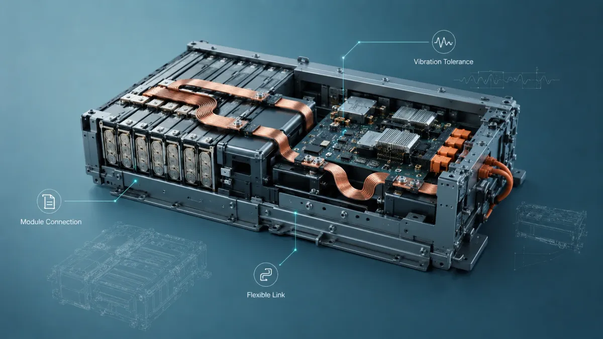
Flexibar is most attractive when the conductor needs to absorb small mechanical differences without stressing the connected devices. This is common in compact power systems because no real assembly is perfectly aligned. Batteries have tolerance stack-up. Cabinets have sheet metal variation. Terminals may shift after welding or coating. Components expand during thermal cycling. In a vibration environment, a rigid part can transfer repeated mechanical stress to bolts, terminals, plastic housings, and welded joints.
A laminated flexible copper busbar can solve these problems by providing controlled flexibility in the middle of the conductor. The terminal areas remain robust, while the flexible section absorbs offset or movement. This is especially valuable in EV battery module bridges, BESS rack links, inverter connections, compact switchgear links, generator connections, and machine connections.
JUMAI’s Battery Busbar Design Guide for EV Battery Packs and Energy Storage Systems makes a useful point: battery systems rarely use only one type of busbar. A fixed path may use a rigid copper busbar, a module-to-module bridge may use a laminated flexible copper busbar, and a grounding or vibration-sensitive connection may use a braided copper busbar. That pattern appears in many compact power systems outside EVs as well.
Flexibar is also useful when the installed path must be adjusted in the field. A rigid copper bar requires accurate dimensions, accurate bends, and a predictable assembly stack. If the final equipment has uncontrolled tolerance, a rigid bar can create forced assembly. Forced assembly is dangerous because the part may appear to fit, but the stress remains in the terminals. Over time, that stress can loosen bolts, deform contacts, crack insulation, or create intermittent resistance.
However, flexibility must be engineered. A flexibar should not be bent randomly during installation. The bend radius, bend direction, insulation transition, foil stack, and terminal zone all need clear design rules. If the flexible area is too short, it may fatigue. If the bend is too sharp, copper layers or insulation may be damaged. If the terminal area is poorly compressed or welded, current may not distribute evenly across all layers.
Where Traditional Copper Busbar Still Wins
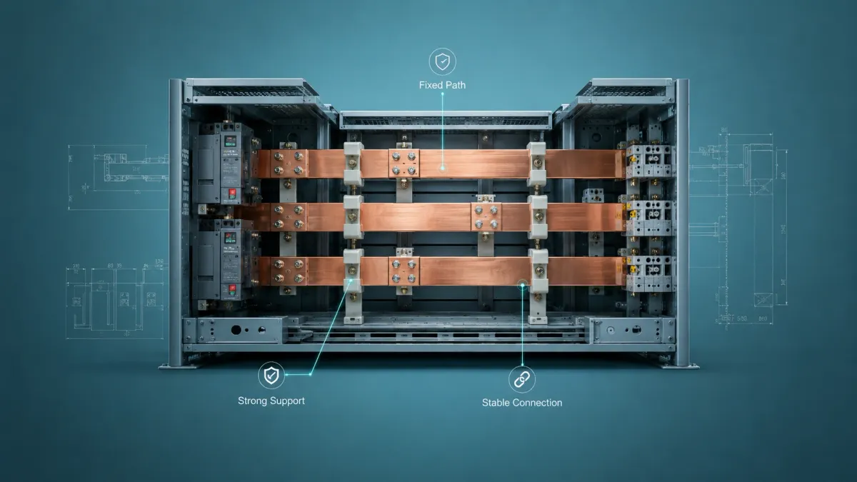
Traditional copper busbar remains the better choice in many compact power systems. This is especially true when the conductor is part of a fixed, repeatable, high-current layout. A rigid copper busbar offers clean geometry, strong mechanical support, and easy inspection. It can be cut, punched, bent, plated, insulated, and checked against a drawing. For OEM production, that repeatability is valuable.
Rigid busbars are often preferred for main DC rails, switchgear distribution, transformer links, power cabinet backbones, fixed inverter bus structures, and equipment where short-circuit forces must be mechanically restrained. A rigid bar can also act as part of the internal layout structure, keeping current paths separated and service areas clear.
In compact systems, rigid busbar can be more space-efficient than buyers expect. A carefully designed flat copper bar may occupy less volume than several large round cables. It may also improve airflow because the conductor path is neat and predictable. In contrast, poorly routed cables can block cooling channels, create service confusion, and add variation from one assembly worker to another.
Molex describes busbars as compact, high-current power distribution solutions for demanding thermal, mechanical, and integration challenges, and notes that rigid busbars can provide high current-carrying capacity, durability, thermal stability, and streamlined integration (Molex Busbars). This matches what many OEM engineers see in practice: if the design is fixed and the tolerance is controlled, a rigid busbar can be the most reliable and cost-effective solution.
The weakness of rigid busbar is not electrical capability. The weakness is mechanical forgiveness. If the installation has vibration, movement, thermal expansion, or uncertain alignment, a traditional rigid bar may need slots, expansion joints, flexible sections, or a different conductor type.
Space Efficiency: Shorter Path Is Not Always Better
In compact power systems, space efficiency is not only about the smallest conductor. It is about the smallest reliable assembly. A flexibar may allow a shorter path between two devices, but the bend must be safe, the insulation must remain intact, and the terminal area must remain flat. A rigid busbar may look larger on the drawing, but it may create a cleaner, more serviceable layout.
A common mistake is to judge by part size instead of assembly size. For example, a round cable may look flexible, but it needs bend radius, lug space, crimping space, tie-down points, and strain relief. A rigid copper busbar may look stiff, but it can bolt directly into a predictable location. A flexibar may be the best of both worlds when the route is short, current is high, and a small amount of flexibility prevents terminal stress.
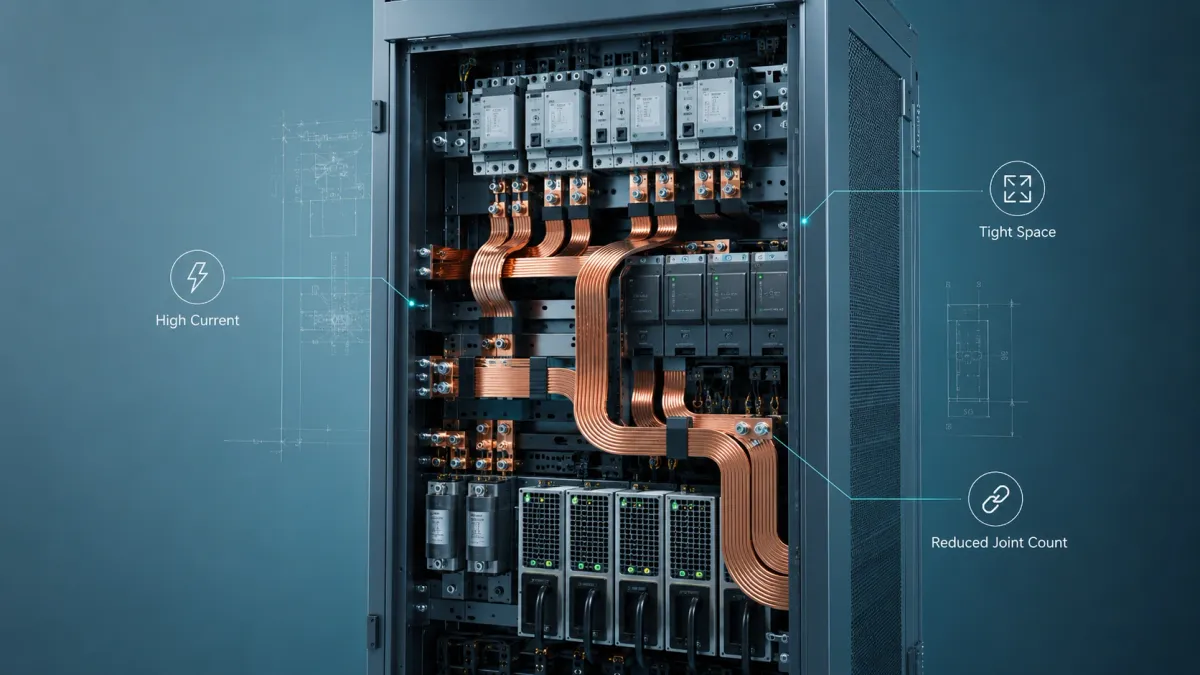
Commercial descriptions of flexibar often emphasize replacing multiple round conductors with one flexible copper bar and reducing the number of lugs or ring terminals. That can be valuable when the original design uses several parallel cables per phase. Fewer conductors can mean fewer crimps, fewer installation steps, fewer routing variations, and fewer contact points. But the exact saving depends on the assembly design.
For a purchasing team, the key question is not “Which part is cheaper?” The better question is “Which design gives the lowest installed cost while meeting thermal, mechanical, and safety targets?” Installed cost includes part price, tooling, assembly labor, inspection, rework, field service, warranty risk, and the cost of redesign if the first layout overheats or fails vibration testing.
Thermal Management in Compact Enclosures
Thermal management is usually the hidden decision-maker. If the conductor runs too hot, it can age insulation, damage nearby components, increase resistance, and reduce equipment life. In compact cabinets, the problem becomes harder because heat sources sit closer together.
A traditional rigid copper busbar has high thermal mass and a predictable geometry. It may transfer heat efficiently to mounting points or heat sinks if designed that way. It can also be spaced from neighboring parts and supported with known clearances. This makes it easier to simulate and inspect.
A flexibar may have a different thermal profile. The layered copper stack can expose surface area, but insulation reduces direct convection from copper to air. The bend shape may also create local areas where airflow is poor. If the flexibar is routed tightly against a device or through a narrow gap, heat may accumulate. This does not mean flexibar is thermally weak. It means the design should not be treated as a simple strip of bare copper.
The safest practice is to evaluate temperature rise in the real enclosure or a representative test setup. IEC 61439-related switchgear design practice places strong emphasis on temperature-rise verification for assemblies. Even when a project is not formally certified under a specific standard, the mindset is useful: verify the conductor as part of the assembly, not as an isolated part.
For high-power data centers, this issue is becoming more important. Molex notes that as power density in data centers rises, thermal constraints affect current capacity and drive the need for reliable, customizable solutions, including liquid-cooled busbars for compact high-power architectures (Molex Busbars). Most projects do not need liquid-cooled busbars, but the trend shows the same principle: current density and thermal design must be considered together.
Safety, Insulation, Creepage, and Clearance
Flexibar is often supplied with insulation, which can make it attractive in compact systems. Insulation can reduce accidental contact risk, help control phase separation, and simplify routing near other components. However, insulation is not magic. Engineers still need to define voltage, pollution degree, creepage, clearance, dielectric test, flame behavior, operating temperature, and environmental exposure.
Socomec describes insulated flexible copper bars as components used to provide power connections between busbars and disconnection devices, and lists conformity references such as VDE 207 Y16, BS 6746, NF A 51-050, VDE 207 YM4, and DIN 40050 for its product family (Socomec Insulated Flexible Copper Bars). Different suppliers and custom manufacturers may use different insulation materials and test methods, so buyers should specify what the final equipment needs instead of assuming every insulated bar is equivalent.
Traditional rigid copper busbars can be bare, plated, powder coated, heat-shrink insulated, epoxy coated, dipped, sleeved, or assembled with insulating supports. A rigid bar may be easier to mask for selective plating or selective insulation windows. A flexibar may need special attention at the transition between the flexible insulated body and the terminal area.
In both cases, the most common safety mistakes are:
- insufficient clearance around punched holes or terminals;
- insulation ending too close to a live edge;
- sharp copper edges cutting insulation;
- wrong insulation material for operating temperature;
- plating or coating not controlled at contact zones;
- bolt hardware reducing creepage distance;
- field bending that damages insulation;
- assuming catalog voltage ratings apply to a custom assembly without validation.
For JUMAI projects, buyers should provide the system voltage, maximum voltage, expected standards, insulation color, required withstand test, exposed copper windows, mounting hardware, and the environment. This allows engineering review before tooling or sample production.
Assembly and Manufacturing Cost
Flexibar often reduces assembly complexity when it replaces multiple cables or avoids difficult rigid-busbar alignment. It may reduce the number of lugs, crimps, cable ties, and routing operations. It may also make service access easier if a connection needs to be removed without forcing a rigid part out of place.
Traditional copper busbar often reduces cost when the design is stable and production volume is consistent. A rigid bar can be manufactured with stamping, CNC punching, bending, deburring, plating, and insulation processes. Once the tooling or fixture is stable, repeatability can be excellent. Inspection can be fast because the geometry is fixed.
The cost comparison should include more than copper weight. A thicker rigid bar may use more copper in one area but eliminate expensive cable labor. A flexibar may cost more per piece than a simple flat bar but reduce assembly time and tolerance-related rework. A custom hybrid busbar may look more complex than either option but prevent field failure.
JUMAI is well positioned for this type of cost engineering because its copper busbar work is connected with punching, bending, plating, insulation, deep-drawn parts, stamping dies, and tooling support. The Custom Copper Busbars service page explains that JUMAI manufactures rigid, braided, and laminated flexible busbars and supports custom punching, bending, plating, and insulation according to CAD specifications. For buyers, this means the discussion can focus on total assembly design rather than only one metal strip.
Application-by-Application Recommendation
Different compact power systems have different priorities. The table below gives a practical recommendation for common industries served by JUMAI.
| Application | Flexibar Is Usually Better When… | Traditional Copper Busbar Is Usually Better When… | Recommended Strategy |
|---|---|---|---|
| EV battery pack | Module positions vary, vibration is high, and the link must absorb thermal expansion | The path is fixed, braced, and part of the main HV distribution structure | Use laminated flexible busbars for module bridges and rigid busbars for fixed pack-level distribution |
| BESS rack | Rack tolerances, module replacement, or field service access require flexibility | Main DC rails and cabinet distribution need fixed geometry | Combine rigid rack rails with flexible module links |
| Solar inverter / PCS | Short connections around capacitors, contactors, or power modules need compact routing | A stable DC bus or AC output bar must be repeatable and thermally predictable | Use flexibar for difficult short links and rigid busbar for main power paths |
| Data center rack PDU / power shelf | Tolerance absorption and serviceable compact links are required | Backplane-style power distribution needs controlled geometry and airflow | Use rigid copper busbar for distribution backbone, flexible links for connection interfaces |
| Switchgear / control cabinet | Device terminals do not align perfectly or field wiring space is limited | Main busbar system needs short-circuit bracing and fixed clearances | Use rigid busbar for main bus system; use flexibar between devices and disconnectors |
| Industrial machinery | Vibration, movement, or thermal cycling would stress a rigid bar | The conductor is mounted in a fixed protected area | Use braided or laminated flexible busbar near moving/vibration zones |
| Transformer / busduct interface | Alignment tolerance or expansion joint behavior is needed | Straight high-current connection is fixed and well supported | Use flexibar or braided links as transition sections |
This table should be read as a starting point, not a rulebook. The final choice depends on current, voltage, temperature, available space, movement, standards, maintenance, and production process.
Flexibar in EV and BESS Power Systems
EV battery packs and BESS racks are among the strongest use cases for flexibar and laminated flexible busbar designs. These systems combine high current, high voltage, vibration, thermal cycling, and compact packaging. A rigid copper busbar may be perfect for a fixed pack-level connection, but it may not be ideal for every module-to-module bridge.
A battery pack is not a perfectly static object. Cells heat and cool. Modules expand slightly. Vehicle vibration creates repeated mechanical load. The enclosure may deform under road conditions. Service teams may need to remove modules or replace components. A laminated flexible copper busbar can help absorb these effects while maintaining a low-profile current path.
However, EV and BESS busbars must be specified carefully. Engineers should define voltage rating, insulation color, orange HV identification if required, copper grade, plating, bolt stack, hole size, torque, bend area, and test requirements. If the busbar includes sensing tabs, fuse features, welded terminals, or overmolded insulation, those features should be shown in the drawing.
For more EV-specific guidance, JUMAI’s Battery Busbar Design Guide and Flexible Copper Busbar for EV Batteries, BESS and Power Distribution provide additional context. Those articles are useful when a project team is deciding between rigid, laminated flexible, braided, and hybrid battery busbar assemblies.
Flexibar in Data Centers and High-Density Power Shelves
Data centers are becoming a major driver of compact high-current power distribution. AI servers, GPU racks, high-density PDUs, power shelves, UPS systems, and busway interfaces all need clean and reliable conductor paths. In these systems, the choice between flexibar and rigid copper busbar is strongly connected to airflow, serviceability, power density, and assembly repeatability.
A traditional rigid copper busbar is often ideal for rack-level distribution because it creates a fixed backbone. It can keep current paths organized, reduce cable clutter, and support repeatable assembly. In a high-density rack, predictable geometry can also help airflow. Random cable loops and inconsistent routing can block cooling paths or make service more difficult.
Flexibar becomes attractive at the interfaces. A short flexible laminated connection may help connect a power shelf to a busbar backbone, compensate for tolerance between modules, or route around compact components. It may also reduce the need for multiple parallel cables in a short connection area.
JUMAI’s article Bus Bar for Server Rack Power Distribution: What Data Center Buyers Should Know explains why custom copper busbar design is important in rack power distribution. In many data center projects, the best design is a structured rigid power path with flexible sections only where they add mechanical or assembly value.
Flexibar in Switchgear, Cabinets, and Industrial Equipment
Switchgear and industrial cabinets often use both conductor types. Main horizontal and vertical busbars are usually rigid because they must be supported, spaced, braced, and inspected. Device connections may use flexible copper bars where terminal positions vary or where installation needs more tolerance.
This pattern is common around molded-case circuit breakers, disconnect switches, transformers, contactors, soft starters, VFDs, generators, and busduct transitions. A rigid main busbar provides structure. A flexibar connection makes it easier to connect devices without forcing alignment.
The advantage becomes obvious during assembly. A panel builder may be able to connect devices faster with a formed flexibar than with multiple large cables. It may also make the cabinet cleaner and easier to service. But if the connection is long, unsupported, exposed to mechanical damage, or needs exact phase spacing, a rigid busbar may still be better.
Buyers should also consider short-circuit behavior. A rigid busbar can be mechanically braced. A flexible conductor may move under fault forces if not supported correctly. For switchgear and high-fault-current systems, the conductor choice should be reviewed as part of the complete assembly design.
When Flexibar Is the Better Choice
Flexibar is usually the better choice when the project has several of the following conditions:
- the available space is tight and a short folded path is needed;
- the connection must absorb small alignment errors;
- the equipment experiences vibration or thermal cycling;
- several parallel cables could be replaced by one cleaner conductor;
- the connection is between devices rather than a long fixed distribution backbone;
- assembly labor and routing variation are major cost concerns;
- the project needs insulated flexible routing with a defined copper path;
- the layout may change during prototype development;
- the design needs a transition between rigid structures.
Flexibar is especially useful in compact systems where the conductor is not only carrying current but also protecting terminals from mechanical stress. If the connected devices are expensive, fragile, or difficult to replace, reducing stress can be more valuable than saving a small amount of copper.
When Traditional Copper Busbar Is the Better Choice
Traditional copper busbar is usually the better choice when the project has these conditions:
- the conductor path is fixed and repeatable;
- the busbar needs mechanical strength or structural support;
- short-circuit bracing is important;
- the connection is a main distribution path rather than a tolerance link;
- dimensional inspection and repeatability are priorities;
- selective plating or selective insulation windows must be tightly controlled;
- the design needs consistent spacing for creepage, clearance, and service access;
- the assembly volume is high and tooling can be optimized;
- the environment does not require much movement absorption.
Rigid busbars are not outdated. In many compact power systems, they are the cleanest and most reliable option. The problem is not rigid copper. The problem is using rigid copper in a location that needs flexibility.
The Best Answer Is Often a Hybrid Busbar Assembly
Many buyers ask, “Which is better, flexibar or traditional copper busbar?” A more useful question is, “Where should the system be rigid, and where should it be flexible?”
A hybrid design may use a rigid copper busbar for the main current path, a laminated flexible copper busbar for a short tolerance zone, and a braided copper strap for grounding or vibration absorption. This approach is common in EV battery packs, BESS cabinets, server rack power systems, and industrial machinery.
A hybrid assembly can also help control cost. Instead of using expensive flexible conductor everywhere, the design uses it only where it solves a real mechanical or assembly problem. Instead of forcing rigid busbars into difficult terminal offsets, the design adds a flexible section where it protects the system.
JUMAI’s manufacturing capabilities support this type of project because the company works with rigid busbars, laminated flexible busbars, braided busbars, plating, insulation, punching, bending, and related stamped or deep-drawn components. A buyer can send the complete power path rather than separately sourcing each conductor type without system-level review.
How to Specify a Custom Flexibar or Rigid Copper Busbar
A good RFQ makes the supplier faster and more accurate. A weak RFQ creates assumptions, and assumptions create risk. For a compact power system, the manufacturer should know how the part will be used, not only what the outline looks like.
| RFQ Item | What to Provide | Why It Matters |
|---|---|---|
| Drawing files | 2D PDF/DWG and 3D STEP/IGES if available | Allows DFM review for bends, holes, tolerances, and assembly fit |
| Application | EV battery, BESS rack, inverter, UPS, switchgear, data center PDU, machinery, or other | Helps the supplier understand vibration, temperature, safety, and inspection needs |
| Conductor type | Flexibar / laminated flexible busbar, rigid busbar, braided busbar, or “need recommendation” | Prevents the supplier from quoting the wrong conductor architecture |
| Current profile | Continuous current, peak current, peak duration, duty cycle | Required for cross-section, heat, and terminal design |
| Voltage | Nominal voltage, maximum voltage, AC/DC, transient requirement | Required for insulation, creepage, clearance, and testing |
| Environment | Ambient temperature, enclosure type, airflow, vibration, humidity, chemical exposure | Influences copper size, insulation, plating, and fatigue risk |
| Material | C11000/T2 copper, oxygen-free copper, tinned copper, or customer specification | Controls conductivity, formability, and sourcing |
| Surface finish | Bare copper, tin plating, nickel plating, silver plating, selective plating | Affects oxidation resistance and contact behavior |
| Insulation | Heat shrink, PVC, silicone, epoxy, powder coating, dipping, color, exposed windows | Controls safety, appearance, voltage protection, and assembly |
| Terminals | Hole size, slot size, bolt, torque, washer stack, contact surface, flatness | Poor terminal design is a common cause of hot spots |
| Testing | Dimensional inspection, plating thickness, insulation withstand, pull test, temperature rise, sample validation | Aligns quality control with real project risk |
| Quantity and schedule | Prototype quantity, annual volume, target delivery | Helps select tooling, fixture, and process route |
If you are unsure whether the part should be flexibar, rigid busbar, or braided busbar, state that clearly. A qualified busbar manufacturer can review the layout and recommend a more practical structure.
Manufacturing Details Buyers Should Not Ignore
The visible shape of a busbar is only one part of the design. Manufacturing details decide whether the part performs reliably.
For flexibar, important details include foil thickness, number of layers, terminal bonding method, insulation material, bend zone length, exposed copper window, terminal flatness, hole punching quality, edge burr control, and plating condition. The flexible zone should be designed so it can move without concentrating stress at the terminal.
For traditional rigid busbar, important details include copper thickness, bend radius, grain direction, punching clearance, burr removal, hole-to-edge distance, bend-to-hole distance, flatness, twist, plating thickness, coating adhesion, and masking quality. A thick copper bar with a poor bend or sharp burr can create assembly and insulation problems.
For braided copper busbar, important details include wire diameter, braid density, terminal compression, solder or welding method, plating, fatigue resistance, and corrosion protection. Braided links are excellent for movement, but their terminal quality must be controlled.
This is where a custom manufacturer adds value. A buyer may only see the final conductor, but the supplier must control material selection, tooling, forming, surface treatment, insulation, inspection, and packaging.
Quality Control: What a Serious Supplier Should Check
A serious busbar supplier should not rely only on visual inspection. Depending on project requirements, quality control may include:
- material certificate review;
- copper thickness and width measurement;
- hole position and slot size inspection;
- bend angle and bend location inspection;
- burr and edge condition inspection;
- terminal flatness inspection;
- plating thickness and adhesion checks;
- insulation thickness and coverage checks;
- dielectric withstand test where required;
- continuity and resistance checks where required;
- packaging protection for plated and insulated surfaces.
For prototype builds, it is also useful to check assembly fit before mass production. A flexibar may fit physically but still have a bend that is too tight for long-term reliability. A rigid busbar may match the drawing but still create stress if the customer’s assembly stack is different from the CAD model. Early sample review prevents expensive production changes.
Common Mistakes in Flexibar and Busbar Projects
The most common mistake is treating the conductor as a commodity. In compact power systems, the busbar is part conductor, part mechanical component, part thermal path, and part safety-critical interface.
Another mistake is copying an old cable ampacity mindset into a busbar design. Busbars and cables lose heat differently. A cable may be surrounded by insulation and bundled with other cables. A busbar may be flat, exposed, plated, insulated, or enclosed. The real temperature depends on the assembly.
A third mistake is underestimating contact resistance. Many overheating problems happen at the joint, not in the middle of the copper. Poor surface flatness, insufficient bolt torque, wrong washer selection, oxidation, contamination, or undersized contact area can create local heat even if the copper cross-section is large.
A fourth mistake is asking for flexibility without defining movement. Flexibility has direction, amplitude, frequency, and life-cycle requirements. A part that can be bent once during installation is different from a part that must survive repeated vibration.
A fifth mistake is ignoring insulation transitions. In both flexibar and rigid busbar designs, the exposed copper window and insulated section must be designed together. If insulation ends too close to the terminal or is damaged by a bend, the system may fail safety testing.
Why Work With JUMAI for Custom Flexibar and Copper Busbar Projects?
JUMAI is a practical manufacturing partner for buyers who need custom copper conductors rather than off-the-shelf parts. The company focuses on custom soft, hard, and braided copper busbars, while also supporting deep drawn components, stamping die customization, and precision tooling. This is useful for compact power systems because the busbar often interacts with brackets, terminals, covers, spacers, housings, and other metal parts.
For a flexibar project, JUMAI can review whether a laminated flexible copper busbar is appropriate, how the terminal area should be designed, where the bend zone should be placed, and whether plating or insulation needs to be adjusted. For a rigid busbar project, JUMAI can review copper size, bend sequence, punching, edge quality, plating, insulation windows, and mass-production repeatability.
For hybrid systems, JUMAI can help divide the power path into functional zones: rigid where the design needs structure, laminated flexible where it needs compact movement, and braided where it needs multi-directional vibration absorption. This is often the most realistic solution for EV, BESS, server rack, UPS, inverter, and switchgear buyers.
The value is not only manufacturing. It is manufacturing feedback before the design becomes expensive to change.
FAQ: Flexibar vs Traditional Copper Busbar
Is flexibar always better than a traditional copper busbar?
No. Flexibar is better when the connection needs compact routing, tolerance absorption, vibration resistance, or easier installation in a tight space. Traditional copper busbar is better when the power path is fixed, needs mechanical strength, requires short-circuit bracing, or benefits from predictable geometry. Many compact systems use both.
Is flexibar the same as a braided copper busbar?
No. In most engineering discussions, flexibar refers to an insulated laminated flexible copper bar made from stacked copper strips. A braided copper busbar is made from woven fine copper wires with pressed, welded, or brazed terminals. Flexibar is usually better for low-profile compact power links. Braided busbar is usually better for multi-directional movement and vibration absorption.
Can flexibar replace cable?
Sometimes. Flexibar can replace multiple large cables in short low-voltage power connections, especially where cable bend radius, lugs, and routing complexity create problems. However, cable may still be better for long flexible runs, field wiring, or applications that require high movement over long distances. The decision should be based on current, voltage, space, movement, installation labor, and serviceability.
Can flexibar carry the same current as a rigid copper busbar?
It can carry high current when designed correctly, but the answer depends on cross-section, length, insulation, cooling, terminal design, allowable temperature rise, and installation environment. Do not compare only nominal amp ratings. Compare the complete conductor system.
Which is better for EV battery packs?
For EV battery packs, laminated flexible copper busbars are often better for module-to-module bridges and tolerance zones. Rigid copper busbars are often better for fixed high-voltage distribution paths, fuse links, and contactor connections. A hybrid layout is usually the best engineering approach.
Which is better for data center rack power systems?
Rigid copper busbars are often better for the distribution backbone because they provide clean geometry and predictable airflow. Flexibar can be better for short interface links where tolerance, service access, or compact routing is important. JUMAI’s server rack bus bar guide explains this context in more detail.
What information should I send to JUMAI for a custom quote?
Send drawings, current rating, peak current, voltage, application, copper grade, surface finish, insulation requirement, terminal hardware, operating temperature, vibration condition, expected standards, prototype quantity, and annual volume. If you are unsure about the conductor type, send the assembly layout and ask for a recommendation.
Final Recommendation
For compact power systems, flexibar and traditional copper busbar are not enemies. They are different tools.
Choose flexibar when your design needs a short, compact, flexible, insulated, high-current connection that can absorb tolerance, vibration, or thermal movement. Choose traditional copper busbar when your design needs fixed geometry, high mechanical strength, predictable inspection, short-circuit bracing, and repeatable mass production. Choose a hybrid busbar assembly when the power path contains both fixed structural zones and flexible tolerance zones.
For OEM buyers, the smartest purchasing decision is to involve the busbar manufacturer early. A small design change in bend location, hole position, foil stack, plating, insulation window, or terminal structure can reduce heat, improve assembly, avoid stress, and lower total cost.
If your project involves EV battery packs, BESS cabinets, data center power shelves, UPS systems, inverters, switchgear, or industrial machinery, JUMAI can review your drawings and help determine whether flexibar, rigid copper busbar, braided copper busbar, or a custom hybrid solution is the better fit. Start with the real application conditions, not only the part shape. That is how compact power systems become safer, cleaner, and easier to manufacture.