Copper busbars sit at the heart of every serious high-current power distribution system. Whether you are designing EV battery packs, data center PDUs, renewable energy inverters, industrial switchboards, or rail traction systems, the way you design and manufacture the copper busbar will determine how safe, efficient, and compact your final product can be.
This guide is written from the perspective of a custom copper busbar manufacturer. Our goal is to help design engineers, purchasing managers, and project owners understand the key design parameters, standards, and manufacturing choices that drive performance and cost in high-current copper busbar solutions.
Instead of drowning you in formulas, we’ll walk through the design logic step by step—how to size the copper busbar, control temperature rise, layout joints and holes correctly, and ensure that what looks good in CAD can actually be manufactured reliably at scale. Along the way, we’ll reference independent standards and technical guides so you can validate your decisions with authoritative data and tables.
Table of Contents
1. Why Copper Busbars Are the Backbone of High-Current Systems
1.1 Electrical and Thermal Advantages of Copper
The reason copper busbar remains the default choice for high-current applications is simple: copper offers outstanding electrical and thermal conductivity in a compact cross-section. High conductivity reduces I²R losses, which translates directly into lower heat generation, higher efficiency, and more stable operation under heavy load.
Thermally, copper conducts heat away from hot spots much more effectively than most alternatives. This allows you to carry high current in a relatively small profile while staying within the temperature-rise limits imposed by standards such as IEC 61439-1, which sets a maximum temperature rise of 105 K for bare copper busbars in low-voltage assemblies. Cognitor+1
In practical terms, efficient copper busbar design means you can push more amps through less metal, saving space in your cabinet or pack and often reducing total system cost compared to oversized cable harnesses.
1.2 Typical High-Current Use Cases
High-current copper busbar systems show up in almost every power-intensive sector you can think of. Switchboards and distribution panels rely on solid or laminated busbars to route thousands of amps across short, controlled distances. EV and hybrid vehicles use flat, 3D-formed busbars instead of bulky cables for battery interconnects and inverters to save space and improve reliability. Interplex
Data centers use copper busbars in PDUs and busway systems to move large currents efficiently to racks, while renewable energy systems use busbars in inverters, combiner boxes, and energy storage modules. In each case, the same fundamental design questions apply: How much current must the copper busbar carry? How hot can it get? What clearances and creepage distances are required? How will it behave during fault conditions?
1.3 Copper vs. Aluminum Busbars
Aluminum busbars are sometimes considered for cost and weight reasons, but they require a significantly larger cross-section to achieve the same electrical and thermal performance as copper. For example, one industry whitepaper notes that for equivalent electrical/thermal performance, the cross-section of an aluminum busbar will be roughly double that of a copper busbar (e.g., 2 mm Al vs 1 mm Cu), especially relevant in tight EV and HEV packaging. Interplex
In high-current, compact environments—particularly where joint reliability, thermal cycling, and long-term stability are critical—copper busbar remains the preferred option. Aluminum can be attractive for overhead or long-distance distribution, but for dense equipment like switchgear, data center power, and vehicle electrification, copper’s smaller size and stable joint behavior often deliver a better total cost of ownership.
2. Key Design Parameters for Copper Busbars
2.1 Current Rating and Current Density
The starting point for any copper busbar design is the required continuous current rating. Once the system current is known, the next step is selecting a cross-section (width × thickness) that keeps current density within safe limits, considering installation conditions and cooling.
There is no single “magic number” for current density in standards like IEC 61439; instead, compliance is typically verified by temperature-rise tests or by calculation using validated reference designs. However, many engineers use 1.2–1.6 A/mm² for copper busbar as a practical design guideline for enclosed LV switchgear with natural ventilation, adjusting up or down based on ambient temperature, enclosure size, and cooling. LinkedIn+1
For more detailed ampacity data, resources such as the Copper Development Association’s busbar tables provide current ratings for common copper busbar sizes under specified temperature-rise conditions. copper.org These references are extremely useful during preliminary sizing and allow you to quickly check whether your proposed cross-section is realistic.
Recommended external resource:
– Copper.org Busbar Ampacity Tables copper.org
2.2 Temperature Rise and Thermal Management
Current density and temperature rise go hand in hand. Every amp flowing through a copper busbar generates I²R losses that appear as heat. Standards such as IEC 61439-1 limit the allowable temperature rise for busbars and components (e.g., 105 K for bare copper busbars, with maximum absolute temperatures around 140 °C for copper conductors in low-voltage switchboards). Schneider Electric Blog+1
Your design must ensure that, under worst-case load, the busbar surface temperature remains below these limits. This is influenced by:
- Cross-sectional area (and thus resistance per meter)
- Length of the busbar and current path
- Enclosure size, airflow, and ventilation
- Proximity of other heat sources (transformers, power electronics, etc.)
Technical guides such as Copper for Busbars – Guidance for Design and Installation from the Copper Alliance discuss temperature rise, energy efficiency, jointing, and short-circuit stresses in depth and should be part of any serious busbar design toolkit. EEP – Electrical Engineering Portal
Recommended external resource:
– Copper for Busbars – Guidance for Design and Installation EEP – Electrical Engineering Portal
2.3 Voltage Drop and Energy Efficiency
In high-current LV systems, voltage drop along a copper busbar run is usually small because lengths are relatively short and cross-sections large. However, in applications with long busway sections or distributed loads (e.g., data center busway, PV busbars), voltage drop can become a significant efficiency factor.
Designers should calculate the resistive voltage drop using the busbar resistance (Ω/m) from material tables and verify that total drop remains within system limits. Reducing voltage drop may require increasing cross-section, shortening the current path, or using laminated busbars with multiple parallel conductors to lower overall resistance.
Lower I²R losses not only improve efficiency but also reduce internal heating, leading to cooler operation and potentially longer equipment life. In industries where energy costs are a major OPEX item, optimizing busbar resistance can deliver measurable savings over the lifetime of the installation.
2.4 Short-Circuit Withstand and Mechanical Strength
High-current systems must survive short-circuit events without catastrophic damage. During a fault, magnetic forces between copper busbars can be extremely high, especially at tens of kA. The mechanical strength of the busbar, its supports, and its joints must be sufficient to withstand these forces for the duration of the rated fault clearance time.
Standards such as IEC 61439 and UL 891 require type tests or calculations to verify short-circuit withstand. ABB Library+1 Busbar spacing, bracing distance, support materials, and fastening methods all influence the ability of the system to handle dynamic forces. Under-designed busbar support structures can deform under fault conditions, reducing clearances and creating flashover risks.
Proper calculation or testing of short-circuit forces—and coordination with protective devices—ensures both safety and compliance for your copper busbar assembly.
3. Geometry, Layout, and Insulation Choices
3.1 Selecting Cross-Section and Profile
Once current rating and thermal limits are defined, you can translate them into specific busbar dimensions. Common cross-sections for copper busbar include:
- Flat rectangular bars (e.g., 40 × 5 mm, 80 × 10 mm)
- Laminated stacks of thinner copper strips
- Custom profiles with chamfered or rounded edges for better electric field distribution
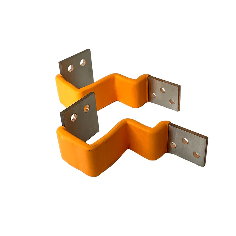
Rectangular bars are easy to manufacture and mount but may require spacing or stacking to achieve higher currents. Laminated busbars use multiple thin layers separated by insulation; these can reduce inductance and improve thermal performance in high-frequency or fast-switching power electronics, while also enabling compact 3D routing. Interplex
At JUMAI TECH, we combine precision stamping, bending, and machining to produce complex copper busbar profiles that fit directly into tight enclosures, EV battery modules, and power converter housings without additional adapter plates.
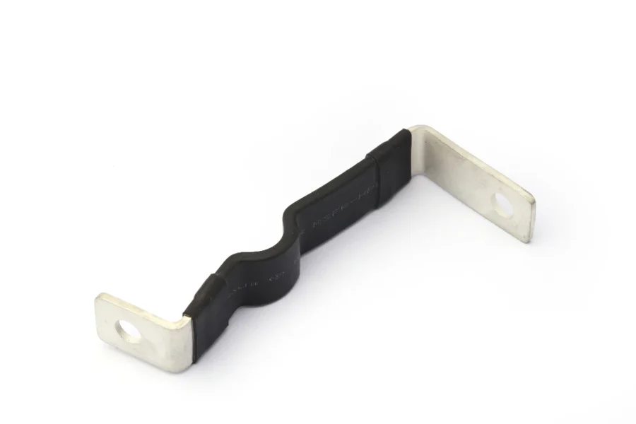
3.2 Hole Patterns, Joints, and Contact Areas
Bolted joints are the most common method for joining copper busbars to each other and to equipment terminals. Design of the overlapping area is critical: current density in the joint should be kept lower than in the busbar body to avoid hot spots and accelerated oxidation. Recent technical guidance suggests limiting current density in the overlapping contact area to around 0.31 A/mm², including bolt-hole area, to ensure long-term reliability. Green Energy Electrical Co.
When designing joints in your copper busbar:
- Ensure enough overlap length and width to keep contact current density low
- Avoid placing holes too close to busbar edges to maintain mechanical strength
- Use proper surface preparation (cleaning, brushing, plating if needed) to reduce contact resistance
- Select bolt size, torque, and washer type to maintain stable clamping force over the product lifetime
For very high-current or vibration-prone applications, alternative joining methods such as friction stir welding, laser welding, or riveted joints may be considered and are discussed in depth in busbar design guides from the Copper Alliance and other industry sources. p537794.webspaceconfig.de+1
3.3 Insulation, Clearance, and Creepage
Even though copper busbars are often bare, high-current systems must respect clearance and creepage distances to prevent arcing and tracking. The required clearances depend on system voltage, pollution degree, and overvoltage category defined in standards such as IEC 61439. ABB Library
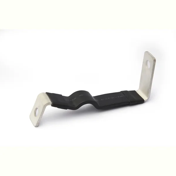
There are several options for insulating copper busbar conductors:
- Heat-shrink sleeves or extruded insulation tubing
- Powder-coating or epoxy insulation
- Laminated busbars with dielectric films between layers
Recent busbar design articles for MV and LV switchgear highlight the increasing use of insulation sleeves (XLPE, silicone rubber, polyester, etc.) to improve phase-to-phase isolation and reduce the risk of flashover in compact metal-enclosed gear. Weisho Electric Co., Ltd.
Good insulation design allows you to reduce air clearances and shrink enclosure size while maintaining or even improving safety margins.
4. Manufacturing Considerations: From Prototype to Mass Production
4.1 Material Selection and Surface Finishes
For most high-current applications, copper busbar is made from high-conductivity electrolytic tough pitch (ETP) copper with a conductivity of ~99.9% IACS. In environments where hydrogen embrittlement, corrosion, or special joining processes are a concern, oxygen-free copper (OF or OFE) may be selected.
Surface finish is another important lever. Bare copper offers excellent conductivity but oxidizes over time, increasing contact resistance. Tin plating is a common solution; it balances cost and performance and is widely accepted in LV switchgear and EV battery systems. Silver plating provides even lower contact resistance and better high-temperature behavior but at a higher cost and with more demanding process control.
As a custom copper busbar manufacturer, we help customers choose the right combination of base material and plating based on current rating, environment (humidity, corrosive gases, etc.), connection technology, and lifetime expectations.
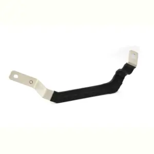
4.2 Forming Technologies (Stamping, Deep Drawing, Bending, Laminating)
Translating your CAD model into a reliable physical busbar requires choosing the right forming technology. Key options include:
- CNC punching and stamping for flat profiles with holes, slots, and complex contours
- CNC bending for 2D and 3D bends with tight tolerances
- Deep drawing and progressive stamping for integrated busbar-plus-housing or busbar-plus-terminal structures
- Lamination of multiple copper layers into a single molded busbar assembly
High-power molded or laminated busbars are especially attractive in EV, inverter, and UPS designs because they can integrate multiple phases and auxiliary circuits into a compact, low-inductance package with excellent repeatability. Interplex
At JUMAI TECH, we combine precision stamping dies, progressive tooling, and deep-drawn components to integrate copper busbars with mounting frames, shielding cans, and connector interfaces. This can significantly reduce part count and assembly time for OEMs.
4.3 Quality Control and Testing
Careful quality control is essential to ensure that every copper busbar produced matches the electrical and mechanical performance predicted in your design. Typical QC and validation activities include:
- Dimensional inspection of cross-sections, bends, and hole positions
- Plating thickness measurements and adhesion tests
- Surface roughness and cleanliness checks at joint areas
- High-potential (Hi-Pot) and insulation resistance tests for insulated busbars
- Thermal imaging under load to detect hot spots
- Type tests for temperature rise and short-circuit withstand, as required by IEC or UL
By integrating quality checks into every stage—from incoming copper strip to final assembly—you avoid latent defects that might only appear in the field under high load or high temperature.
5. Standards and Compliance for Copper Busbar Systems
5.1 IEC 61439 and Temperature-Rise Verification
For low-voltage switchgear and controlgear assemblies (up to 1000 V AC / 1500 V DC), the primary global standard is IEC 61439. It defines how assemblies must be designed, built, and tested, including temperature-rise tests, dielectric tests, short-circuit withstand, clearances, and creepage distances. Tuling+1
Under IEC 61439-1, manufacturers can verify current ratings and temperature rise either by testing a representative assembly or by calculation using verified reference designs. Temperature rise limits for busbars and components are specified assuming a 35 °C ambient and limited maximum service temperatures. LinkedIn+1
Designers using copper busbar must ensure that their chosen dimensions, layout, and ventilation strategy allow the assembly to pass these tests. Working with a manufacturer experienced in IEC 61439 can significantly reduce project risk and time-to-market.
Recommended external resource:
– Schneider Electric: IEC 61439 Rated Current & Temperature Rise Schneider Electric Blog
5.2 UL 891 and North American Switchboard Requirements
For the North American market, UL 891 is the key standard for low-voltage dead-front switchboards (typically up to 600 V or 1000 V AC). It defines construction and test requirements to ensure safe operation, including clearances, insulation, mechanical strength, and temperature-rise limits for busbars and terminals. Gt-Engineering+1
UL 891 compliance is usually demonstrated by type testing complete switchboard assemblies, including their copper busbar systems, under worst-case load conditions. Design-for-UL-891 requires attention not only to electrical performance, but also to markings, labeling, compartmentalization, and accessibility. UL Standards Store+1
If you plan to market in North America, it is essential to work with a busbar manufacturer familiar with UL 891 and the interplay with NEC Article 408, EUSERC requirements, and local utility specifications.
Recommended external resource:
– UL 891 Switchboard Standard Overview Gt-Engineering
5.3 Documentation, Traceability, and Certification
From an OEM perspective, a good copper busbar partner is more than just a metal supplier. They should deliver:
- Complete drawings and 3D models with material and plating specifications
- Process documentation for stamping, bending, and plating
- Material certificates and traceability back to copper batch and lot
- Test reports for temperature rise, short-circuit withstand, and insulation as applicable
- Clear labeling and marking schemes that support UL / IEC compliance
This documentation supports your own design verification and simplifies audits by end customers, certification bodies, or utilities.
6. Partnering With JUMAI TECH for Custom Copper Busbars
6.1 Our Engineering Workflow
At JUMAI TECH, we specialize in precision copper busbar solutions for high-current, high-reliability applications. Because we also design and manufacture deep-drawn components, precision stamped parts, and progressive stamping dies, we are able to integrate busbars into larger mechanical and electrical assemblies—reducing part count and improving consistency.
Our typical engineering workflow looks like this:
- Application review – We discuss your system (voltage, current, duty cycle, ambient, standards to meet) and review existing drawings, 3D models, or legacy components.
- Preliminary design & feasibility – Our engineers propose cross-sections, materials, plating, and forming processes that align with IEC, UL, or other target standards, referencing authoritative guides like Copper Alliance and copper.org where needed. copper.org+1
- DFM optimization – We adjust hole patterns, bend radii, and tolerances to match real-world manufacturing capability and lower tooling costs.
- Sampling & validation – We produce prototypes and, if required, support temperature-rise and short-circuit testing on representative assemblies.
- Mass production & quality assurance – Once validated, we ramp to serial production with tightly controlled processes, full traceability, and ongoing feedback loops with your engineering team.
Throughout this process, we act as an extension of your design team, not just a build-to-print supplier.
6.2 Typical Project Timeline
While timelines vary by complexity, a typical custom copper busbar project might follow this pattern:
- 1–2 weeks – Application review, concept design, and DFM feedback
- 2–4 weeks – Tooling preparation for stamping / bending or deep-drawn elements
- 1–3 weeks – Prototype busbar production and basic functional testing
- 4–8 weeks – Validation in your system (thermal, electrical, mechanical), plus any design refinements
- Ongoing – Serial production with controlled lead times and buffer stocks as needed
By involving us early—before the busbar design is frozen—you can often reduce total development time and avoid costly design iterations late in the project.
6.3 How to Get Started
If you’re planning a new high-current system or upgrading an existing design, now is the best time to rethink your copper busbar strategy. Better busbar design can reduce enclosure size, improve efficiency, and simplify assembly—while also making compliance with IEC 61439, UL 891, and customer specifications much easier.
Share your project details with us—target current, voltage, environment, key standards, and any existing drawings or models. Our engineering team will review your requirements and propose a manufacturable, cost-effective copper busbar solution tailored to your application.
Final Thoughts
Designing a copper busbar for high-current applications is not just about choosing a random cross-section and hoping it works. It requires balancing current density, temperature rise, voltage drop, short-circuit forces, mechanical constraints, and manufacturing realities—while staying within the limits of IEC 61439, UL 891, and other relevant standards.
By combining authoritative external references (such as copper.org, Copper Alliance guides, and IEC/UL publications) with practical manufacturing experience, you can create busbar solutions that are safe, efficient, and ready for mass production. And with a partner like JUMAI TECH, you can turn those designs into high-quality, repeatable hardware that supports the long-term success of your products.