In medium-voltage (MV) distribution – often called medium tension (MT) in many regions – the copper busbar is the backbone of safe and reliable power flow. When you select an MT copper busbar for 3.3–36 kV systems, you are not just choosing a piece of metal; you are defining how your switchgear, busduct, or transformer connection will perform over 20–30 years under heat, mechanical stress, and short-circuit faults. Power and Cables
For OEMs and EPC contractors, the challenge is always the same: how to translate standards and theoretical design into a specification for MT copper busbar that suppliers can manufacture consistently, test, and document. In this guide, we’ll walk through the key electrical, mechanical, and thermal specifications you should include, and show how JUMAI TECH supports you with customized busbars, precision stamping dies, and deep-drawn components around your busbar system.
Table of Contents
1. Understanding MT Copper Busbars in Medium-Voltage Systems

1.1 What Does “MT” Mean in Power Distribution?
In many countries, electrical engineers use MT (Medium Tension) as a conventional term for medium-voltage networks, typically in the range of 1 kV up to around 36 kV, depending on the local standard. Medium tension lines and equipment connect primary substations, ring main units (RMUs), industrial plants, and large commercial facilities. Open JICA Report
Within this MV/MT environment, the MT copper busbar is the rigid conductor that distributes power inside metal-clad switchgear, busduct (busway) systems, unit substations and large motor control centers. The busbar defines the current-carrying capacity, short-circuit performance, and thermal behavior of the entire assembly.
1.2 Role of Copper Busbars in MV Switchgear and Busduct
In MV switchgear and metal-enclosed bus duct, copper busbars perform several critical functions:
- Collect and distribute power between incoming feeders, outgoing feeders, and transformer connections.
- Provide a low-impedance path to limit voltage drops and power losses.
- Withstand mechanical forces during short-circuit events without excessive deformation or displacement. ABB Library
Most medium-voltage metal-enclosed bus systems are designed according to IEEE C37.23 or equivalent IEC standards, which define voltage classes up to 38 kV and continuous current ratings that can reach tens of kiloamps for metal-enclosed bus assemblies. IEEE Standards Association
Your MT copper busbar specification therefore becomes a key part of your switchgear or busduct specification, and must align with these higher-level standards.
1.3 Typical Applications for MT Copper Busbars
You will typically find MT copper busbars in:
- Medium-voltage switchgear: 12 kV, 24 kV or 36 kV metal-clad switchgear, ring main units and compact substations. Mitsubishi Electric
- Medium-voltage busduct/busway systems: cast-resin or air-insulated busways interconnecting transformers and switchgear, or running overhead in industrial plants. EAE Elektrik
- Generators and large motor connections: where high currents and short-circuit forces demand rigid copper conductors.
In all of these applications, mt copper busbar design must consider not just current and voltage, but also environmental conditions, insulation type, maintenance strategy, and available footprint inside the enclosure.
2. Key Electrical Specifications of MT Copper Busbars
2.1 Voltage Class and Insulation Coordination
The first step in specifying an MT copper busbar is to define the rated voltage of the system and the associated insulation requirements. Medium-voltage switchgear design guides from major manufacturers show that voltage class directly influences clearances, creepage distances and insulation levels for internal busbars. Power and Cables+1
Key points to define:
- Rated maximum voltage (Um): e.g., 12 kV, 17.5 kV, 24 kV, or 36 kV.
- Impulse withstand level (BIL/LIWV): typically 60–170 kV depending on Um and standard series.
- Power-frequency withstand: the 1-minute AC withstand test value (e.g., 28 kV, 38 kV).
Even though copper is a conductor, your MT busbar specification should clearly describe:
- Minimum phase-to-phase and phase-to-earth clearance in air.
- Required creepage distance over any solid insulation or insulator surfaces.
These parameters are normally derived from IEC/IEEE insulation coordination rules and the particular switchgear or busduct standard you are following. Power and Cables
2.2 Continuous Current Rating (Ampacity)
For MT copper busbars, the continuous current rating is often between 630 A and 5000 A in standard MV switchgear and busway products, with higher currents for special designs. EAE Elektrik
To define the ampacity of your mt copper busbar, engineers usually:
- Choose a copper grade: Typically high-conductivity copper, equivalent to Alloy C11000 (ETP copper) for its excellent electrical properties. WatterEdge
- Select a bar cross-section: width and thickness that give the required cross-sectional area.
- Check the ampacity tables from reputable sources like the Copper Development Association, which provide current ratings for standard copper busbar sizes under defined conditions (ambient temperature, spacing, orientation, and allowable temperature rise). Copper Development Association
- Apply derating factors if your installation has higher ambient temperatures, reduced ventilation, or special enclosure arrangements.
CDA busbar tables and related technical guides are widely used industry references and form a credible external source you can cite in your design specification. p537794.webspaceconfig.de
2.3 Short-Circuit Withstand and Thermal Limits
Beyond continuous current, your MT copper busbar must survive short-circuit events without permanent damage. That means:
- Thermal withstand: Ability to withstand the temperature rise during a fault (e.g., 1–3 seconds at the rated short-circuit current) without melting or annealing beyond acceptable limits.
- Mechanical withstand: Ability to withstand the electrodynamic forces between phases and between bars during high-current faults.
IEC and IEEE busbar and switchgear standards define short-time withstand currents (Ik) and peak withstand currents that busbars and their supports must meet. IEC 61439 and related guides note that bare copper busbars in low-voltage assemblies may have maximum allowable temperature rises up to around 105 K above ambient; similar principles and calculations are applied for MV busbar systems, considering conductor temperature limits and insulation ratings. 16557801101891546621.googlegroups.com
For your specification:
- State the rated short-time current (Ik), e.g., 25 kA, 31.5 kA or 40 kA for 1 s or 3 s.
- State the peak withstand current (Ipk), e.g., 63 kA, 80 kA or higher.
- Require verification according to relevant clauses of IEC / IEEE standards for metal-enclosed bus or switchgear (e.g., IEC 61439-6 for busbar trunking, IEEE C37.23 for metal-enclosed bus assemblies). ABB Library
A supplier like JUMAI TECH will then size the mt copper busbar, supports and joints to meet these fault levels under your specified mechanical constraints and enclosure geometry.
3. Mechanical and Dimensional Specifications
3.1 Copper Grades and Conductivity Requirements
For MT busbars, you should clearly define the copper material and its properties. Typical requirements include:
- Material: High conductivity copper equivalent to C11000 or similar grade with minimum conductivity of 100% IACS (International Annealed Copper Standard). WatterEdge
- Form: Rolled or extruded rectangular bars with controlled grain structure for predictable mechanical strength and bending behavior.
- Surface condition: Clean, oxide-free, deburred edges to ensure reliable bolted joints and stable corona performance at MV levels.
In some specifications, designers require tin-plated copper busbars to improve corrosion resistance and contact performance. Technical specifications for MV switchgear often call for tin-plated copper busbars for improved joint reliability under varying environmental conditions. Mitsubishi Electric
At JUMAI TECH, we work with certified copper mills and can provide mt copper busbar with bare, tin-plated, nickel-plated or silver-plated surfaces depending on your application.
3.2 Cross-Section, Stacking and Compact Layouts
The cross-section of the MT copper busbar directly affects current-carrying capability, temperature rise, and mechanical stiffness. Engineers typically:
- Use wide, relatively thin bars for better heat dissipation and lower temperature rise.
- Stack multiple bars in parallel per phase to reach higher current ratings while staying within practical dimensions. Electrical Engineering Book
Your specification should include:
- Nominal width and thickness for each phase busbar (e.g., 80 × 10 mm, 100 × 10 mm).
- Number of bars per phase (e.g., 2 × 80 × 10 mm in parallel).
- Phase spacing (center-to-center distance) to satisfy insulation and electrodynamic force requirements.
Well-designed mt copper busbar systems balance mechanical strength, dielectric clearances and thermal performance, especially in compact metal-clad switchgear and MV busway where space is limited but fault currents are high.
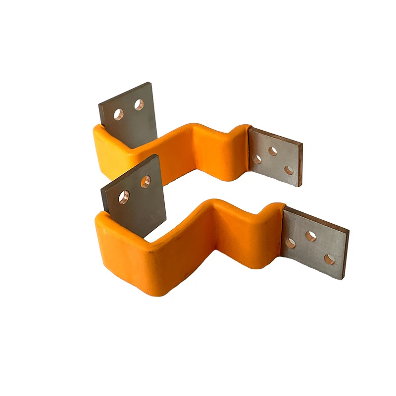
3.3 Bending, Hole Patterns and Tolerances
An MT copper busbar is rarely just a straight bar. It typically includes:
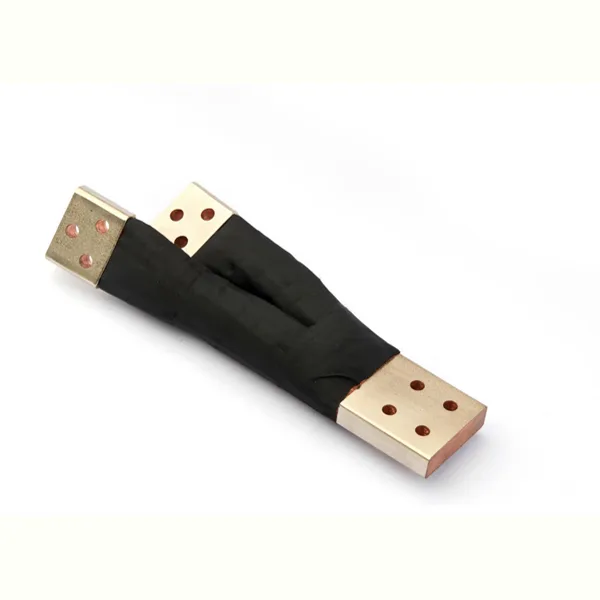
- Bends and offsets to align with equipment terminals, bushings and cable connection points.
- Drilled or punched holes for bolted connections, joint packs and accessories.
When working with a precision manufacturer, it is best to provide:
- 3D or 2D drawings showing all bends (angles, inner radii) and hole patterns.
- Dimensional tolerances for critical interfaces, such as ±0.3 mm for hole locations or ±1.0 mm for overall length, depending on your assembly needs.
Because JUMAI TECH also designs precision stamping dies and deep-drawn components, we can integrate items like contact brackets, terminal pads or mounting flanges directly with the mt copper busbar design, reducing part count and assembly time for OEMs.
4. Insulation, Coatings and Thermal Management
4.1 Bare vs Insulated MT Copper Busbars
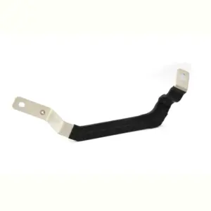
Medium-voltage busbars can be:
- Bare copper busbars mounted on epoxy or porcelain insulators inside metal-clad compartments (common in traditional switchgear). Mitsubishi Electric
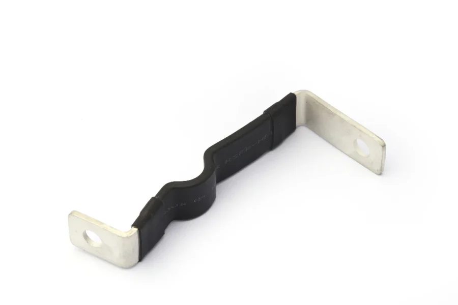
- Insulated busbars, where the copper is covered with cast resin, heat-shrink sleeves, or epoxy coatings to increase dielectric strength and reduce the risk of flashover in compact spaces. EAE Elektrik
For an mt copper busbar in a compact MV system, insulation options include:
- Heat-shrinkable tapes or sleeves specifically designed for MV busbar insulation, applied with overlap and heat to create a continuous, adhesive-lined insulation layer. Etelec Italia S.p.A. Energia Connessa
- Cast-resin encapsulation, as used in some MV busway systems, offering robust environmental protection and mechanical strength. EAE Elektrik
Your specification should state:
- Whether the MT copper busbar is to be supplied bare or insulated.
- Insulation class and thickness (e.g., minimum 3 mm epoxy coating, specified dielectric strength).
- Environmental category, such as indoor, outdoor, pollution level, and any special requirements (e.g., high humidity, corrosive atmosphere).
4.2 Temperature-Rise Limits and Busbar Heating
Heat is one of the primary design constraints for any mt copper busbar. Busbars generate heat due to I²R losses, eddy currents, and proximity effects; this heat must be dissipated through conduction, convection and radiation to keep the conductor and surrounding insulation below their permitted temperatures.
IEC 61439-1 and related documents discuss temperature-rise limits for copper busbars and other components, with typical guidelines indicating that bare copper busbars may be allowed a temperature rise of around 105 K above ambient, provided the absolute conductor temperature and insulation limits are not exceeded. 16557801101891546621.googlegroups.com
For MV systems, equipment manufacturers often adopt similar or slightly more conservative limits, taking into account:
- Maximum ambient temperature (commonly 40 °C).
- Allowable conductor temperature for copper and insulation.
- Ventilation conditions inside the enclosure or busduct.
When you specify an mt copper busbar, it is good practice to:
- Define the ambient temperature and installation conditions used for rating (e.g., 40 °C ambient, enclosed switchgear, natural ventilation).
- Request type test reports demonstrating compliance with specified temperature-rise limits for the busbar system from a recognized manufacturer or test laboratory. ABB Library
4.3 Ventilation, Derating and Enclosure Design
Even if an MT copper busbar is correctly sized according to ampacity tables, its real-world performance depends heavily on the enclosure design:
- Poor ventilation can raise internal temperatures significantly.
- High current density and tight phase spacing can increase local hot spots.
- Additional losses may come from enclosure eddy currents and other conductors nearby. ABB Library
When you work with JUMAI TECH, our engineering team can:
- Review your 3D switchgear or busway layout for potential hot spots and suggest busbar arrangement improvements.
- Propose optimized bar configurations and spacing to reduce temperature rise and magnetic forces.
- Coordinate with your mechanical team to include ventilation openings, heat-dissipating fins or other design features in the enclosure.
I’ve covered the introduction plus the first major chapters on electrical, mechanical, and thermal specifications for mt copper busbar.
If you’d like, I can continue with:
- Standards, testing, and documentation requirements
- A step-by-step MT copper busbar selection checklist
- A marketing-focused section on why global OEMs should partner with JUMAI TECH
so the full article exceeds 2000 words and is ready for direct publishing on deepdrawtech.com.
FAQ
What is an MT Copper Busbar?
An MT Copper Busbar is a strong metal conductor that helps distribute electricity in medium-voltage systems, like within switchgear or transformers. It’s essential for carrying electrical currents safely and efficiently, and plays a crucial role in the performance of electrical systems over many years.
How does the MT Copper Busbar work?
The MT Copper Busbar collects and distributes electrical power from various sources, like transformers and feeders. It ensures that electricity flows smoothly without overheating or losing too much energy, which helps keep electrical systems operating correctly and safely.
Why is copper used for busbars?
Copper is used for busbars because it is an excellent conductor of electricity, meaning it allows electrical currents to flow easily. It also has good thermal properties, helping to manage heat, and is strong enough to withstand the stresses during electrical faults.
What are the common applications for MT Copper Busbars?
You can find MT Copper Busbars in various applications, such as in medium-voltage switchgear, busway systems, and connections for large motors and generators. They’re ideal for settings where high electricity currents are present, like industrial plants and commercial buildings.
What factors should be considered when choosing an MT Copper Busbar?
When selecting an MT Copper Busbar, you need to consider the voltage rating, continuous current capacity, insulation needs, and the busbar’s dimensions and material grade. This ensures it performs well under specific conditions and meets safety standards.
What happens if there is a short-circuit in a busbar system?
If a short-circuit occurs, the MT Copper Busbar must be able to withstand the sudden surge of electricity without being damaged. It has to endure high temperatures and forces during such events, which is critical for preventing further damage to the electrical system.
How do I maintain MT Copper Busbars?
Maintaining MT Copper Busbars includes regular inspections for corrosion, ensuring connections are tight, and checking insulation. It’s also important to monitor the operating temperature and ensure the busbars are not overloaded during use.
Are MT Copper Busbars insulated?
MT Copper Busbars can be either bare (not covered) or insulated with various materials like resin or epoxy. Insulating helps protect against accidental contact and can improve the busbar’s capacity to handle electrical stress.
What is the typical lifespan of an MT Copper Busbar?
Generally, an MT Copper Busbar can last anywhere from 20 to 30 years if it’s installed correctly and maintained properly. Factors affecting its lifespan include environmental conditions, temperature management, and electrical loading.
How can JUMAI TECH help with MT Copper Busbars?
JUMAI TECH supports customers by providing customized MT Copper Busbars designed to meet specific needs, along with precision components and thorough documentation. Expert assistance is available for selecting the right specifications for different applications.