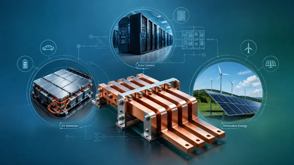
A copper busbar looks simple at first sight: a strip, plate, foil stack or braided conductor that moves current from one point to another. In real projects, however, a copper busbar is not only a piece of metal. It is a controlled electrical path, a thermal component, a mechanical interface, an insulation boundary, a contact system and a manufacturable part that must survive assembly, vibration, temperature rise, coating, shipping and years of service.
That is why buyers in electric vehicle batteries, data centers and renewable energy systems rarely succeed by choosing copper only by thickness and price. The correct copper busbar must match current, voltage, available space, cooling condition, mounting method, contact pressure, plating, insulation, creepage and clearance, production quantity and the actual way the system will be assembled. A busbar that works on a drawing can still fail in production if bend radius, hole tolerance, burr direction or coating window is ignored.
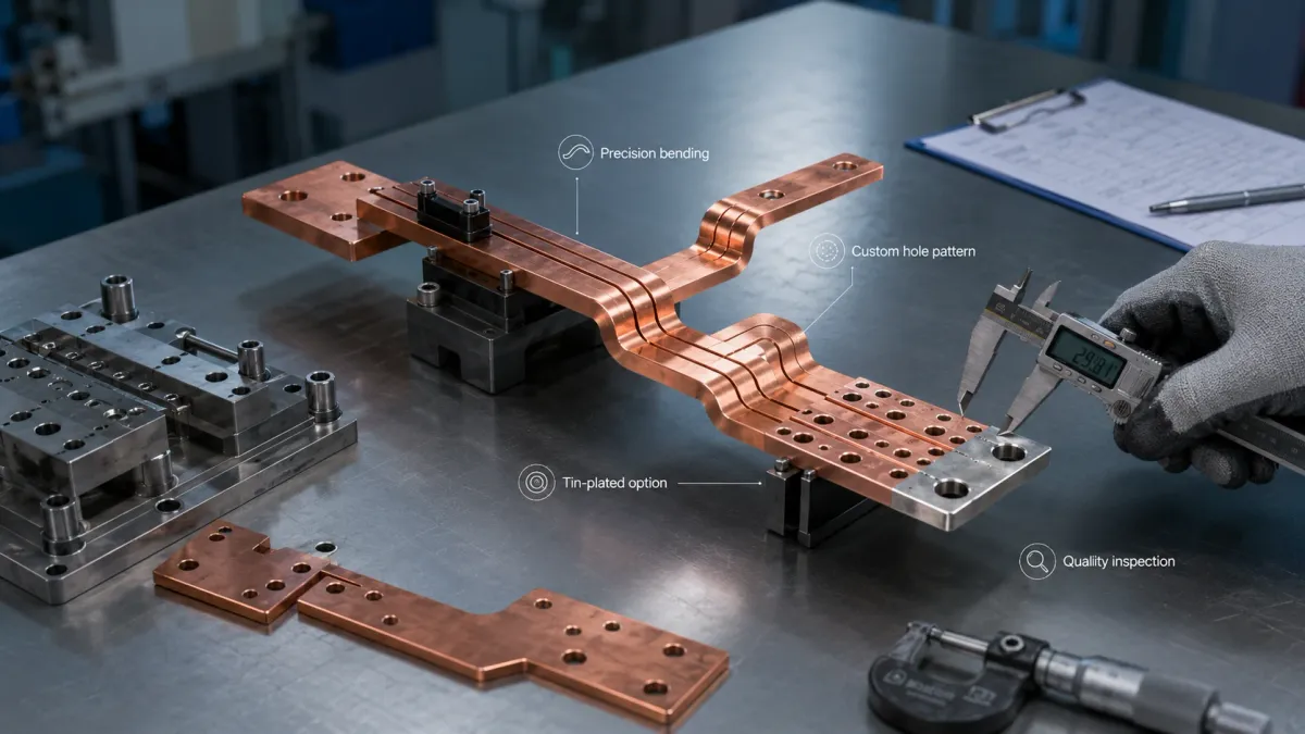
JUMAI focuses on custom soft, hard and braided copper busbars for global customers. The company manufactures custom copper busbars using high-purity T2/C11000 copper and supports punching, CNC bending, plating, insulation, cold pressing for braided terminals and diffusion welding for laminated flexible designs. JUMAI also supports related deep drawn components, stamping die customization and tooling and mold components when the buyer needs a complete electrical-mechanical assembly rather than a single copper strip.
This guide is written for engineers, product managers and sourcing teams who need a practical way to specify a copper busbar for EV battery packs, battery energy storage systems, AI server racks, UPS cabinets, solar inverters, wind power converters and low-voltage power distribution. It combines industry data, design rules, manufacturing experience and business-oriented RFQ advice, so that your team can move from concept to quote with fewer redesigns.
- Why copper busbar design is becoming more important
- What a copper busbar does inside a power system
- Copper busbar types and when to choose each one
- Why copper is still preferred for high-current conductors
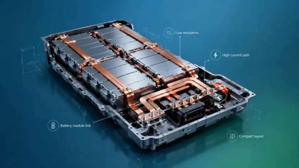
- Copper busbars in EV battery packs
- EV battery busbar design details that affect reliability
- Copper busbars in AI data centers and rack power distribution
- Data center busbar design details that affect uptime
- Copper busbars in renewable energy and BESS systems
- Application comparison: EV batteries, data centers and renewable energy
- Copper grade selection: C11000, T2, C10100 and oxygen-free copper
- Surface finish and insulation choices
- Ampacity, voltage drop and temperature rise
- Low inductance and high-frequency behavior
- Creepage, clearance and insulation coordination
- Manufacturing process: from drawing to production copper busbar
- Deep drawing, stamping and tooling support around busbar projects
- RFQ checklist for a custom copper busbar
- Common design mistakes to avoid
- How JUMAI supports copper busbar projects
- Practical specification template
- FAQ
- Final recommendation
Why copper busbar design is becoming more important
Electrification is increasing the amount of current that must be moved safely inside smaller spaces. EV battery packs are becoming denser. Data centers are moving toward high-power AI clusters and 48 V rack architectures. Renewable energy projects require inverters, power conversion systems, switchgear and storage cabinets that can handle frequent cycling and high current. In all three markets, the busbar is no longer a secondary accessory. It is one of the parts that determines system efficiency, thermal behavior and service reliability.
The market signals are clear. According to the International Energy Agency, global electric car sales are expected to reach 23 million in 2026, or about 28% of all car sales, in its Global EV Outlook 2026 executive summary. In the same outlook, the IEA projects EV battery deployment to rise from around 1.2 TWh in 2025 to almost 3 TWh by 2030 in current and stated policy scenarios, as described in its section on electric vehicle batteries. For data centers, the IEA projects global data center electricity consumption to reach about 945 TWh by 2030 in its Energy and AI analysis. For renewables, the IEA projects almost 4,600 GW of renewable power capacity additions from 2025 to 2030 in Renewables 2025.
These figures do not mean every project uses the same copper busbar. They mean the opposite: as volumes rise, design discipline becomes more important. A good supplier must understand why a flexible laminated conductor is better in one battery module, why a rigid plated busbar is better in one inverter, why a braided connector is safer near a vibrating machine, and why a data center rack busbar must be designed around contact resistance, airflow and installation repeatability.
| Market or technical signal | Data point from public sources | What it means for copper busbar buyers |
|---|---|---|
| EV adoption | Global electric car sales are expected to reach 23 million in 2026, or 28% of total car sales, according to the IEA Global EV Outlook 2026. | Battery modules, pack-level HV distribution and charging interfaces need more repeatable copper busbar designs. |
| EV battery deployment | EV battery deployment is projected to grow from about 1.2 TWh in 2025 to almost 3 TWh by 2030 in IEA scenarios. | More pack platforms will need laminated flexible, rigid-flex and insulated copper busbars. |
| Data center load growth | The IEA projects global data center electricity use to roughly double to about 945 TWh by 2030. | Rack busbars, UPS conductors, PDUs and power shelves need lower loss and better thermal control. |
| Renewable power expansion | Renewable power capacity is projected to increase by almost 4,600 GW from 2025 to 2030. | Solar inverters, wind converters, BESS cabinets and switchgear need scalable high-current interconnects. |
| Copper material baseline | The Copper Development Association lists C11000 as high-conductivity copper with minimum 100% IACS conductivity in the annealed condition. | C11000/T2 copper is a practical baseline for many custom busbar projects. |
| 48 V rack current density | The Open Compute Project ORv3 power output connector specification lists 46-52 V DC and high continuous current ratings, including 360 A in still air and 500 A with airflow for the power contact. | Data center busbar joints must be treated as engineered contact systems, not only copper cross-section. |
What a copper busbar does inside a power system
A copper busbar distributes electrical energy between components. It may connect battery cells, modules, fuses, contactors, shunts, relays, inverters, capacitors, power modules, circuit breakers, transformers, rectifiers or rack-level power shelves. A busbar can be flat, bent, folded, laminated, braided, insulated, plated, punched, threaded, welded, riveted or assembled with inserts and covers.
The most common reason to use a copper busbar instead of cable is control. A busbar gives the designer a defined current path and a repeatable geometry. It can be installed quickly, inspected visually and designed to fit tight packages. When shaped correctly, it can reduce assembly errors, lower inductance in power electronics layouts, improve heat spreading and reduce voltage drop. When insulated correctly, it can also improve safety in high-voltage or high-density equipment.
Copper is preferred in many busbar applications because it combines high electrical conductivity, good thermal conductivity, ductility, formability and corrosion resistance. The Copper Development Association describes C11000 copper as a high-conductivity material with a minimum conductivity of 100% IACS in the annealed condition and a minimum copper content of 99.90%. The U.S. Geological Survey also notes that copper is widely used because of its high ductility, malleability, thermal and electrical conductivity and resistance to corrosion, with electrical uses representing a major share of copper consumption.
In simple terms, copper helps the system move current with lower resistance. Lower resistance reduces voltage drop and heat generation. That matters because heat is not only an efficiency issue. Heat accelerates aging of insulation, loosens contact interfaces through thermal cycling, increases resistance further and can create thermal runaway risks in battery systems if the design is poor. A good copper busbar is therefore a reliability part, not only a conductor.
Copper busbar types and when to choose each one
A buyer who searches for copper busbar may receive very different quotations because suppliers may be thinking about different product types. The right structure depends on the application. JUMAI’s Copper Busbar Guide explains the practical differences between rigid, laminated flexible and braided copper busbars. The selection is not about which type is universally best. It is about matching electrical load, mechanical movement and assembly constraints.
| Copper busbar type | Best fit | Key design points |
|---|---|---|
| Rigid copper busbar | Switchgear, UPS cabinets, inverters, power distribution units, fixed battery pack paths and industrial control panels. | Check cross-section, bend radius, hole tolerance, flatness, contact area, edge radius, plating and cabinet clearance. |
| Laminated flexible copper busbar | EV battery modules, BESS racks, compact converters and tight spaces where a controlled bend or twist is needed. | Specify foil thickness, layer count, terminal welding area, insulation material, bend zone and minimum bend radius. |
| Braided copper busbar | Vibration-heavy equipment, grounding, moving interfaces, thermal expansion compensation and misalignment correction. | Define braid cross-section, wire finish, terminal size, cold-pressed area, pull strength, movement direction and plating. |
| Rigid-flex or hybrid busbar assembly | Battery packs, renewable energy cabinets and custom power modules where one part must combine fixed routing and flexibility. | Divide the part into fixed, flexible and contact zones; define coating windows, inspection gauges and assembly sequence early. |
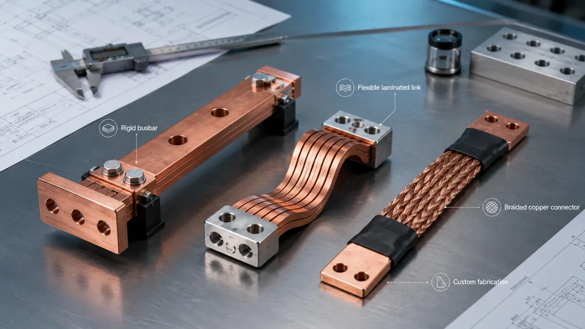
Rigid copper busbars are usually cut or stamped from copper plate or strip, then punched, bent, plated and sometimes insulated. They are easy to inspect and suitable for high-volume production because the geometry is stable. They are a strong choice when the installed components do not move and the power path must be robust.
Laminated flexible copper busbars are usually made from stacked thin copper foils. The terminal zones are pressed, welded or diffusion bonded, while the middle section remains flexible. This structure is popular in EV battery modules and compact energy storage systems because it allows the conductor to absorb small tolerances and thermal expansion without forcing stress into the cell terminals or power terminals. JUMAI’s Flexible Busbar vs. Cable comparison explains why flat laminated conductors can be easier to route than large round cables in tight spaces.
Braided copper busbars are made from woven copper wires, often with bare, tinned or plated surfaces. They are useful where vibration, movement or installation mismatch is expected. The terminal area is normally cold pressed, welded or otherwise consolidated to create a stable bolted contact. A braided conductor is not automatically better than a laminated flexible busbar. It is better when multi-directional movement and vibration absorption matter more than a flat controlled geometry.
Why copper is still preferred for high-current conductors
Aluminum busbars are used in many power systems, especially where weight and material cost are major drivers. Aluminum can be a rational choice in large fixed distribution systems if the designer accepts a larger cross-section and manages oxide, creep and joint design carefully. Copper remains the preferred choice in many high-current custom parts because it allows a smaller cross-section for the same resistance, supports compact packaging, and provides excellent thermal spreading.
The practical business advantage is often not simply lower electrical loss. It is easier packaging. In an EV battery pack, every millimeter matters. In a data center power shelf, current density and airflow matter. In a solar inverter, copper paths must fit around capacitors, IGBTs, SiC modules, sensors and protective barriers. If a copper busbar reduces conductor size, simplifies assembly and prevents rework, the value can exceed the difference in raw metal cost.
JUMAI’s article on why copper is still the preferred material for high-current conductors makes a useful point for procurement teams: busbar copper is not a commodity decision only. It is an electrical, mechanical and manufacturing decision. The final cost is influenced by copper grade, thickness, tooling, bending, welding, plating, insulation, inspection method, packing and the cost of failures. A lower piece price may be expensive if the part overheats, is difficult to install or requires manual correction on the production line.
A useful way to evaluate copper versus aluminum is to ask four questions. First, does the enclosure have enough space for a larger conductor if aluminum is used? Second, can the joint maintain stable contact resistance over temperature cycling? Third, will the application face vibration or movement? Fourth, will the supplier control plating, surface preparation and torque recommendations? If the answer to any of these questions is uncertain, copper often becomes the safer choice.
Copper busbars in EV battery packs
EV battery packs are among the most demanding copper busbar applications because they combine high current, limited space, vibration, thermal cycling and high-voltage safety. The copper busbar may connect cells inside a module, modules inside a pack, the pack to a fuse, the fuse to a contactor, the contactor to a current sensor, or the battery to the inverter and charging interface. Each location has a different mechanical and electrical requirement.
The EV battery busbar should be designed as part of the pack architecture, not added after the cells and enclosure are fixed. A module interconnect may need to absorb tolerance between cells. A pack-level conductor may need to route around coolant plates, service disconnects and structural beams. A high-voltage distribution busbar may need insulation and touch-safe protection. A current collector near the inverter may need low inductance. A grounding braid may need high flexibility and fatigue resistance.
For EV battery projects, the most important design questions are current, voltage, temperature rise, isolation, vibration and assembly sequence. Current determines the required cross-sectional area and contact design. Voltage determines insulation, creepage and clearance. Temperature rise determines conductor width, thickness, heat sinking and allowable contact resistance. Vibration determines whether a rigid, laminated flexible or braided copper busbar is appropriate. Assembly sequence determines hole access, torque access, coating windows and whether the part can be installed without bending it beyond its intended range.
A useful starting point is JUMAI’s Battery Busbar Design Guide, which explains how battery busbars should be treated as engineered power paths. In EV packs, the most common mistake is copying the copper cross-section from an old design without checking the new thermal environment. A 200 mm2 conductor in free air does not behave the same as a 200 mm2 conductor inside a sealed battery pack beside hot cells. Similarly, a bolted joint with clean silver-plated contact surfaces does not behave the same as a joint with oxide, burrs or poor torque control.
Standards also shape design. ISO 6469-3:2021 specifies electrical safety requirements for voltage class B circuits in electrically propelled road vehicles, including protection against electric shock and thermal incidents, as summarized on the official ISO 6469-3:2021 page. Product teams must also consider OEM specifications, regional regulations, creepage and clearance requirements, environmental tests, vibration tests and insulation withstand requirements. The copper busbar supplier does not certify the full vehicle, but it must manufacture the component in a way that supports the customer’s certification path.
In EV batteries, laminated flexible copper busbars are often chosen between modules because they can compensate for tolerance and thermal expansion. Rigid busbars are often used in fixed pack-level high-current paths where geometry is stable. Braided copper busbars are useful for grounding, vibration compensation and flexible current paths near moving or tolerance-sensitive interfaces. Many packs use a combination of all three.
EV battery busbar design details that affect reliability
The first electrical calculation is usually simple. Resistance is proportional to length and inversely proportional to cross-sectional area. The basic relationship is:
R = rho x L / A
where R is resistance, rho is the resistivity of the copper, L is conductor length and A is cross-sectional area. Voltage drop is:
Vdrop = I x R
Heat generated in the conductor is:
P = I^2 x R
These formulas are simple, but the real design is not simple because the copper body is only one part of the heat path. Contacts can generate more local heat than the straight conductor. For example, a short copper section with a low body resistance may only dissipate a few watts, but a poor bolted joint can add a small resistance that becomes a serious hot spot at high current. At 400 A, only 50 micro-ohms of extra contact resistance produces 8 W of heat at the joint. That heat is concentrated in a small area, often near insulation and plastic structures.
This is why contact design should be discussed before production. The buyer should define contact area, hole diameter, washer type, plating, torque range, surface flatness, burr direction and whether the part will be assembled once or serviced repeatedly. Tin plating is often selected for general corrosion protection and solderability. Nickel plating can be useful in harsher environments and as a diffusion barrier. Silver plating may be selected where very low contact resistance and stable high-current interfaces are required, although it increases cost.
Insulation is equally important. Heat shrink tubing is useful for straight or moderately bent parts. PVC dipping or coating can cover complex shapes but requires good control of thickness and coating windows. Epoxy powder coating can provide a tough insulated surface for rigid or laminated busbars, but the designer must define uncoated contact areas precisely. Silicone or TPE insulation may be selected where flexibility or temperature performance is important. Flame behavior should be defined carefully. UL Solutions explains that the UL 94 vertical burning test is used to determine V-0, V-1 and V-2 ratings by evaluating burning, afterglow and dripping behavior.
Mechanical details are also critical. Tight bend radii can thin the outer radius and create stress. Holes too close to bends can distort. Sharp edges can cut insulation. Burrs can damage neighboring parts or reduce contact quality. An EV battery busbar drawing should therefore include edge break, burr direction, plating zone, insulation zone, bend tolerance, flatness requirement and inspection datum. For laminated flexible busbars, the drawing should also define the flexible section and terminal consolidation method. For braided copper busbars, the drawing should define braid length, terminal dimensions and allowable movement.
Copper busbars in AI data centers and rack power distribution
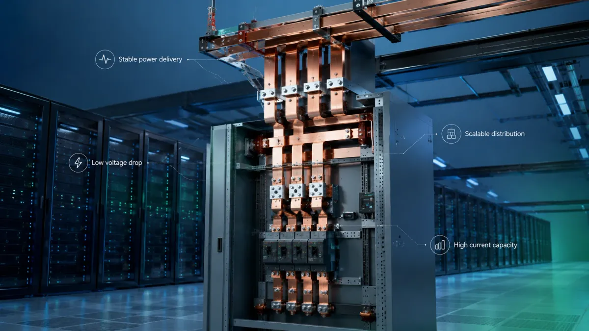
Data center power distribution is changing because high-density compute loads and AI accelerators demand more current at the rack and board level. A traditional data center power chain may include utility input, switchgear, UPS, busway, rack PDU, power shelf, server power conversion and board-level distribution. Copper busbars appear at many points in this chain. They may be used inside switchboards, UPS cabinets, busway plugs, power shelves, rack-level vertical distribution, battery backup systems and high-current server assemblies.
The design goal in data centers is uptime. A busbar that saves a little money but creates heat, voltage drop, installation complexity or field maintenance risk is not attractive. High-current data center components also face a special challenge: the power system may be modular, but the load can be very dynamic. GPU clusters can ramp quickly, and the power distribution path must handle load transients without excessive voltage drop or thermal stress.
The move toward 48 V DC rack architecture is a good example of why copper busbar design matters. Open Compute Project ORv3 documents define 48 V rack interfaces and power connections. The OCP Open Rack V3 Power Output Connector specification lists a 46.0 V to 52.0 V DC range and high continuous current levels for the power contact, including ratings with still air and airflow. These values show that a rack power interface is not merely a wire replacement. It is a contact, busbar, airflow, voltage-drop and temperature-rise problem.
JUMAI’s article Bus Bar for Server Rack Power Distribution explains that a rack busbar is a custom electrical-mechanical component. It must match rack geometry, blind-mate or bolted interfaces, plating, insulation and assembly tolerances. For data center buyers, this means the RFQ should include more than a copper size. It should include voltage, current, allowable voltage drop, temperature-rise target, airflow condition, contact method, surface treatment, expected service cycles and whether the conductor is part of a larger rack assembly.
Copper busbars are also used inside UPS and power distribution equipment. For low-voltage assemblies, IEC 61439-1:2020 lays down general definitions, service conditions, construction requirements, technical characteristics and verification requirements for low-voltage switchgear and controlgear assemblies, as described on the IEC 61439-1 page. Data center equipment may also need to meet product-specific standards, regional electrical codes and customer specifications. A busbar supplier supports that process by delivering consistent material, dimensions, plating and insulation, but the system integrator must verify the complete assembly.
Data center busbar design details that affect uptime
For data center copper busbars, the joint is often the risk point. A long straight copper bar can be sized by cross-section and cooling condition, but a connector interface depends on pressure, plating, alignment and installation. A small increase in contact resistance can create local heat. Local heat can relax contact pressure, oxidize surfaces and increase resistance further. This feedback loop is why contact design must be conservative.
A data center busbar should be designed with clear control of contact surfaces. Tin plating can be sufficient in many power distribution applications. Silver over nickel may be used in demanding rack interfaces or high-current contacts where stable low resistance is required. Nickel can improve corrosion performance and act as a barrier layer. The correct choice depends on contact material, mating cycles, environment, temperature and cost. Selective plating is often useful because it gives high performance at the contact area without coating the entire part with the most expensive finish.
Thermal management must be realistic. A busbar inside an open test setup may run cooler than a busbar inside a crowded cabinet. Airflow can dramatically change temperature rise. If the busbar is near heat sources such as power modules or rectifiers, the local ambient temperature may already be high. The drawing or RFQ should therefore define ambient temperature, airflow, duty cycle and temperature-rise target. If these values are unknown, the prototype should be tested under representative conditions rather than judged only by room-temperature resistance.
Mechanical repeatability also matters. Rack-level busbars may be assembled with blind-mate connectors, sliding contacts or bolted joints. Each interface needs dimensional control. Flatness, parallelism, plating thickness and mounting hole tolerance can determine whether contact pressure is stable. If the busbar is part of a modular assembly, the supplier may need inspection fixtures that simulate the mating hardware. This is where a custom copper busbar manufacturer with tooling and fixture experience can reduce risk before mass production.
Copper busbars in renewable energy and BESS systems
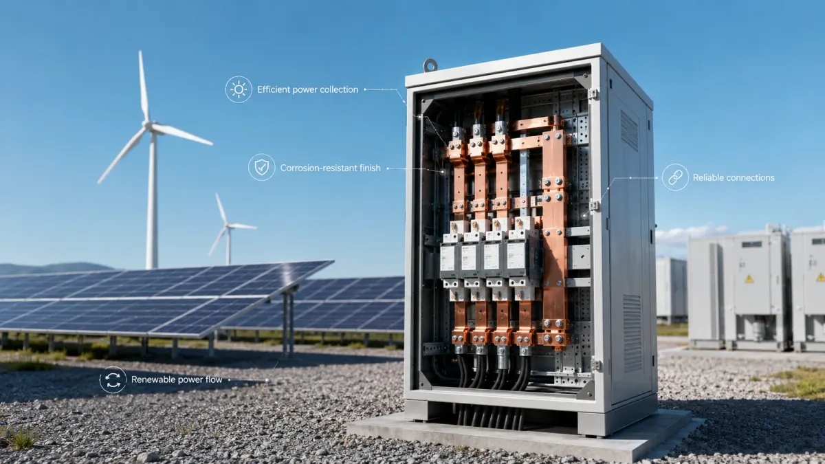
Renewable energy systems use copper busbars in solar inverters, wind turbine converters, combiner cabinets, battery energy storage systems, power conversion systems, DC disconnects, switchgear, transformers and grid connection equipment. The current may be DC or AC. The voltage may range from low-voltage control circuits to high-voltage DC energy storage. The environment may be indoor, outdoor, coastal, dusty, humid or exposed to strong thermal cycling.
The IEA’s Renewables 2025 executive summary projects renewable power capacity to double by 2030, with solar PV making up almost 80% of the increase. This expansion creates demand for power electronics and grid equipment, and these systems depend on reliable current paths. Copper busbars are used to connect DC inputs, capacitors, power semiconductor modules, AC outputs, protection devices and grounding systems.
In solar inverters and PCS equipment, busbar design often focuses on low resistance, low inductance, compact routing and insulation. Wide flat conductors can help reduce inductance compared with long round cables, especially when positive and negative conductors are designed as laminated or parallel paths. In high-frequency switching environments, physical layout matters because stray inductance can increase voltage overshoot and stress semiconductor devices. Laminated busbar structures can be useful when the design requires controlled spacing between conductors, but they must be engineered carefully with insulation layers, edge margins and manufacturing tolerances.
In BESS cabinets, busbars connect battery racks, fuses, contactors, current sensors, DC/DC converters, PCS units and protection devices. The design resembles EV battery busbar design in some ways, but the duty cycle and environment can be different. Stationary storage may face long continuous operation, high ambient temperature, maintenance access requirements and strict safety standards. ANSI/CAN/UL 1973:2022 covers battery systems used for stationary energy storage applications such as PV, wind turbine storage and UPS systems, as summarized on the ANSI page for UL 1973. Busbar components inside these systems must support the broader battery system safety strategy.
Corrosion protection is often more important in renewable energy than in vehicle interiors. Outdoor cabinets, coastal installations and humid environments may require tin or nickel plating, sealed insulation, stainless hardware and better control of galvanic compatibility. Bare copper may be acceptable in some controlled indoor cabinets, but it oxidizes. Oxide does not automatically make a busbar unusable, but it can affect contact quality if it appears at bolted interfaces. The contact zone should therefore be protected or cleaned and assembled according to a defined process.
Application comparison: EV batteries, data centers and renewable energy
The same copper busbar factory may produce parts for all three industries, but the design emphasis is different. EV batteries prioritize packaging, vibration and high-voltage safety. Data centers prioritize uptime, contact resistance and modular installation. Renewable energy systems prioritize long service life, corrosion resistance, thermal cycling and high-current power conversion.
| Application | Typical busbar requirements | Common JUMAI manufacturing support |
|---|---|---|
| EV battery pack and battery module | Compact routing, vibration resistance, controlled flexibility, insulation, creepage and clearance, low voltage drop, repeatable assembly. | Laminated flexible copper busbars, rigid busbars, braided copper links, tin/nickel/silver plating, epoxy or heat-shrink insulation, fixture inspection. |
| AI data center rack, UPS and PDU | High continuous current, low contact resistance, stable temperature rise, precise interfaces, rack-level repeatability and service access. | Rigid copper busbars, plated contacts, flexible busbar or braided links for tolerance compensation, insulation windows, dimensional inspection. |
| Solar inverter, wind converter and BESS cabinet | High-current DC or AC paths, corrosion resistance, insulation, low inductance, thermal cycling resistance and safe maintenance access. | Rigid and laminated copper busbars, selective plating, custom bends, punched holes, threaded features, covers, stamped brackets and deep drawn accessories. |
This comparison helps the buyer avoid generic RFQs. A drawing that only says “copper busbar, 2 mm thickness, tin plated” is not enough for a serious supplier to optimize the part. A better inquiry explains the application and the reason behind the dimensions. For example, a 2 mm thickness may be chosen because of available space, desired flexibility, existing tooling or current rating. If the reason is known, JUMAI engineers can often suggest a more manufacturable option.
Copper grade selection: C11000, T2, C10100 and oxygen-free copper
Material selection begins with conductivity and manufacturability. C11000, also known as electrolytic tough pitch copper, is widely used because it provides high conductivity, good formability and strong availability. In China-related specifications, T2 copper is commonly used for high-purity copper parts and is often treated as a practical equivalent family for many electrical busbar applications. JUMAI’s Custom Copper Busbars page describes the use of high-purity T2/C11000 copper for custom busbars.
C10100 or other oxygen-free copper grades may be selected when the application requires better performance in certain welding, brazing, vacuum or high-temperature reducing environments. Oxygen-free grades can cost more and may not be necessary for standard bolted busbars. The correct question is not “which copper is the best?” but “which copper is best for this process and this risk?” JUMAI’s article on C10100 vs C11000 copper busbar selection discusses the tradeoff between conductivity, weldability, ductility and cost.
The buyer should also consider copper temper. Annealed copper is softer and easier to form. Harder tempers can provide more strength but may be less forgiving in tight bends or deep forming. Cold working can change resistance slightly and affects springback. For a busbar with multiple bends, the supplier should confirm bend feasibility and whether the part needs intermediate annealing or process controls.
Surface finish and insulation choices
Surface finish is not decoration. It protects copper from oxidation, improves contact behavior and supports assembly. Tin plating is common for many electrical connections because it is cost-effective and provides corrosion protection. Nickel plating is often used for harsher environments, higher temperature exposure or as a diffusion barrier. Silver plating is used when low contact resistance and high-current performance are more important than coating cost.
Insulation must be selected based on voltage, environment, bend requirements and safety standards. Heat shrink tubing is simple and economical, but it may not fit complex 3D geometry well. PVC dipping can cover irregular shapes but must be controlled for thickness and masking. Epoxy powder coating can provide a robust insulated surface for rigid busbars, but it requires controlled coating windows and edge preparation. Silicone, TPE or other flexible insulation may be useful for laminated flexible busbars that must bend during assembly.
| Design item | Practical recommendation | Why it matters |
|---|---|---|
| Copper grade | Use C11000/T2 for most high-conductivity busbar applications; consider oxygen-free copper for special welding, brazing or high-vacuum requirements. | Material choice affects conductivity, cost, formability and process risk. |
| Plating | Define bare, tin, nickel, silver or selective plating by contact requirement and environment. | The contact surface often determines long-term resistance more than the copper body. |
| Insulation | Define heat shrink, PVC dipping, epoxy powder coating, silicone, TPE or custom sleeve by voltage and geometry. | Insulation controls safety, spacing, flame behavior and assembly protection. |
| Bend design | Define bend radius, bend angle tolerance, grain direction and distance from holes. | Poor bending can create thinning, cracks, springback and fit problems. |
| Edge and burr control | Add edge radius, deburring and burr-direction notes to the drawing. | Sharp edges can cut insulation and burrs can damage contact surfaces. |
| Contact interface | Define hole size, flatness, contact area, washer, torque range and plating window. | A small contact resistance increase can create a major hot spot at high current. |
| Validation | Request dimensional inspection, resistance checks, insulation checks and sample testing under realistic load. | Prototype results reduce mass-production and certification risk. |
The safest specification is not always the thickest coating or the most expensive plating. Too much coating in a contact area is a defect. Coating on a bend zone may crack if the process is wrong. Silver plating everywhere may be unnecessary. Good design separates functional zones: current-carrying body, contact area, insulated area, bend area, flexible area and inspection datum.
Ampacity, voltage drop and temperature rise
Ampacity is the current a conductor can carry continuously under defined conditions without exceeding its temperature limit. The phrase “under defined conditions” is important. A copper busbar has no single universal ampacity. Current capacity depends on cross-section, surface area, orientation, ambient temperature, enclosure, airflow, adjacent heat sources, allowable temperature rise, plating, insulation and duty cycle. A bare copper bar in free air can carry more current than the same bar inside a sealed plastic housing.
For early design, engineers often start with current density or ampacity charts. These are useful for screening, but they should not replace thermal testing or simulation. The final design should consider conductor body heating and contact heating separately. The conductor body can be estimated from resistance. The contact must be controlled by surface condition, pressure and assembly process.
Consider a simplified example. A 200 mm long copper busbar with a 200 mm2 cross-section has low body resistance. Using a typical copper resistivity value near room temperature, the conductor body may produce only a few watts at 400 A. In contrast, a poor contact adding 50 micro-ohms produces 8 W at the joint. If that joint is near plastic, insulation or battery cells, the local hot spot is much more important than the average conductor temperature.
This is why temperature-rise testing should include real hardware. The test should use the intended fasteners, washers, torque, plating, contact surfaces and cooling condition. If the final product uses an insulated busbar, test the insulated busbar. Insulation can reduce convective cooling. If the final product is inside a sealed enclosure, testing the busbar on a bench in open air is not enough.
For high-current design, it is also useful to specify allowable voltage drop. In a 48 V data center rack, a few millivolts at one interface can matter because current is high and voltage margin is limited. In an 800 V EV pack, the same millivolt drop may be less important for system voltage but still important for heat generation. In both cases, power loss is the product of current and voltage drop, so high current makes small resistance values important.
Low inductance and high-frequency behavior
In DC battery links, resistance and temperature rise may dominate. In power electronics, inductance can be equally important. Fast switching devices such as IGBTs and SiC MOSFETs can generate voltage overshoot if the DC link has excessive stray inductance. Copper busbars can help reduce inductance by controlling conductor geometry.
A laminated busbar places positive and negative conductors close together with insulation between them. This arrangement can reduce loop area and lower inductance compared with separated cables. However, laminated busbars must be designed carefully. The insulation must support voltage stress. Edges must be controlled. Overlap areas must be designed around creepage and clearance. Manufacturing tolerances must be realistic. The supplier must understand how copper layers, insulation layers and terminals are bonded or assembled.
Flexible laminated copper busbars also influence AC behavior. Multiple thin foils can reduce skin-effect impact compared with one thick bar in some alternating or pulsed current conditions. However, this should not be oversold. The real benefit depends on frequency, foil thickness, geometry and current distribution. For most buyers, the practical takeaway is simple: when the system uses fast switching or high ripple current, involve the busbar supplier early and share electrical layout goals, not only mechanical drawings.
Creepage, clearance and insulation coordination
Creepage is the shortest path along an insulating surface between conductive parts. Clearance is the shortest distance through air. Both matter in EV batteries, data centers, renewable energy systems and industrial power distribution. The required distance depends on voltage, pollution degree, material group, altitude, insulation type, overvoltage category and applicable product standard.
IEC 60664-1 is commonly referenced for insulation coordination in low-voltage systems. A public EN IEC 60664-1:2020 catalog summary states that it deals with insulation coordination for equipment up to AC 1,000 V or DC 1,500 V connected to low-voltage supply systems. In practical busbar design, this means the supplier must know the voltage and insulation requirement before finalizing coating windows, cutouts, hole spacing and the distance between adjacent conductors.
Do not assume that coating alone solves all spacing problems. Coating can improve protection, but it must be qualified for the application and applied consistently. Edges, holes and masking boundaries are common weak points. If a busbar has epoxy insulation but the hole edge is poorly masked or sharp, the system can still fail. Good drawings show exposed copper zones, insulation zones, keep-out areas and inspection requirements.
Manufacturing process: from drawing to production copper busbar
A custom copper busbar project usually begins with a 2D drawing, 3D CAD file or application sketch. The supplier reviews material, thickness, bend feasibility, hole locations, tolerance, plating, insulation and production quantity. For simple rigid busbars, tooling may be minimal. For high-volume stamped busbars, progressive tooling can reduce cost. For laminated flexible busbars, process planning must include foil cutting, stacking, terminal consolidation, welding or diffusion bonding, insulation and inspection. For braided busbars, the process includes braid selection, cutting, terminal forming and pressing or welding.
JUMAI’s process on the Custom Copper Busbars page follows a practical path: drawing evaluation, rapid prototyping, mass production, QC and global shipping. This process is important because a busbar that seems simple can have hidden risks. A hole may be too close to a bend. A coating area may cover a contact zone. A bend may be impossible after plating. A terminal may require a special fixture to maintain flatness. Early DFM review prevents these problems.
For production, the key process controls include material certificate, thickness check, flatness, hole position, bend angle, burr removal, surface cleaning, plating thickness, coating thickness, adhesion, insulation withstand, resistance and packing. For EV and data center parts, traceability may also be required. For renewable energy projects, corrosion and environmental requirements may be added. A professional supplier should be willing to discuss the inspection method before production begins.
Deep drawing, stamping and tooling support around busbar projects
Many custom power assemblies need more than a conductor. They may require brackets, covers, terminals, shields, spacers, drawn housings or custom tooling. This is one reason JUMAI’s broader capability is useful for busbar buyers. The company’s Deep Drawn Components service supports seamless metal enclosures and high-strength formed parts. The Stamping Die Customization service supports in-house die design and fabrication for production metal components. These capabilities can support busbar-adjacent parts such as shields, covers, copper terminals and custom fixtures.
For example, an EV battery pack may need a laminated flexible copper busbar, an insulating cover, a stamped bracket and a sensing terminal. A renewable energy cabinet may need rigid copper busbars, copper grounding links, stainless mounting parts and custom protective covers. A data center power shelf may need plated copper conductors and precision metal components that position the interface. Managing these parts separately can create tolerance stack-up problems. A supplier that understands tooling, stamping and busbar manufacturing can help reduce that risk.
Tooling matters most when the project moves from prototype to mass production. A prototype can be laser cut and hand formed, but the production part may need stamping, progressive dies, forming fixtures, welding fixtures and inspection gauges. If the prototype is designed without considering production tooling, cost can rise sharply during scale-up. The best time to discuss tooling is before the design is frozen.
RFQ checklist for a custom copper busbar
A good RFQ reduces quotation time and improves the quality of supplier feedback. If you send only a screenshot, the supplier may quote conservatively or ask many questions. If you send clear design data, JUMAI can review manufacturability and recommend cost-saving changes sooner.
Prepare the following information when possible:
- Application: EV battery module, pack distribution, BESS cabinet, solar inverter, wind converter, UPS, rack PDU, switchgear or other equipment.
- Electrical requirement: continuous current, peak current, duty cycle, voltage, AC/DC, ripple current, target voltage drop and allowable temperature rise.
- Mechanical requirement: envelope, hole positions, thickness, bend angles, bend radius, installation tolerance, vibration and movement.
- Material: C11000/T2 copper, oxygen-free copper or customer-specified grade.
- Busbar type: rigid, laminated flexible, braided or hybrid.
- Surface finish: bare copper, tin plating, nickel plating, silver plating or selective plating.
- Insulation: heat shrink, PVC dipping, epoxy powder coating, silicone, TPE, sleeve, custom molded cover or no insulation.
- Contact design: hole size, fastener, washer, torque, contact surface, plating zone and service cycles.
- Standards and tests: insulation withstand, resistance, pull test, vibration, salt spray, temperature rise, RoHS, REACH or customer-specific requirements.
- Files: 2D drawing, STEP/IGES file, PDF, assembly image, target quantity and prototype schedule.
If some values are unknown, explain the application and constraints. A good supplier can help identify missing data. For example, if you know the current but not the temperature-rise target, JUMAI can ask about enclosure, cooling and insulation. If you know the mechanical envelope but not the best conductor type, JUMAI can suggest whether rigid, laminated flexible or braided copper is more appropriate.
Common design mistakes to avoid
The first mistake is sizing the copper body but ignoring the contact. In high-current systems, the bolted or welded interface is often the hottest point. Define surface finish, flatness, torque and plating.
The second mistake is using a rigid busbar where movement is expected. Battery modules, vibrating equipment and thermally expanding assemblies may need laminated flexible or braided copper busbars. A rigid part can transfer stress into terminals and cause fatigue.
The third mistake is adding insulation too late. Insulation changes bend behavior, thickness, clearance, assembly sequence and heat dissipation. Define coating windows and insulation boundaries during design, not after the copper geometry is frozen.
The fourth mistake is placing holes too close to bends. This can distort holes, reduce contact flatness and create cracks or thinning. Keep functional holes away from high-strain areas when possible.
The fifth mistake is applying unnecessary tight tolerances. Tight tolerances increase cost if they do not support function. Define critical dimensions clearly and allow reasonable tolerances elsewhere.
The sixth mistake is ignoring burr direction. A burr on the wrong side can damage insulation or reduce contact quality. Add deburring and edge-break notes.
The seventh mistake is treating prototype and production as the same. Prototype methods may not scale. Discuss mass-production process, tooling, inspection and packing early.
How JUMAI supports copper busbar projects
JUMAI is positioned for buyers who need more than standard copper stock. The company supports custom rigid copper busbars, laminated flexible copper busbars, braided copper busbars, surface finishing, insulation and related precision metal processing. Its Custom Copper Busbars page describes capabilities including punching, bending, plating, insulation, cold pressing for braided terminals and diffusion welding for laminated busbars. For customers preparing a project, internal resources such as the Copper Busbar Guide, Battery Busbar Design Guide, Flexible Busbar vs. Cable comparison and Busbar Copper Standards and Testing guide provide practical background.
The business value is speed and manufacturability. Buyers can send CAD drawings, sketches or early concepts for review. JUMAI can help check whether the copper cross-section, bend geometry, hole locations, plating zones and insulation concept are realistic. This is especially useful for international buyers who must coordinate electrical engineering, mechanical design and sourcing across different time zones.
JUMAI can support several project scenarios:
- EV battery module links that require laminated flexible copper busbars.
- Pack-level high-voltage copper busbars with insulation and plating.
- BESS rack and cabinet conductors for renewable energy storage.
- AI server rack and UPS copper busbars with stable contact surfaces.
- Braided copper links for vibration, grounding and movement compensation.
- Copper busbars combined with stamped brackets, covers or deep drawn accessories.
- Prototype development before mass-production tooling.
- Design-for-manufacturing review for drawings, bends, holes, plating and insulation.
The best first step is to send a drawing and application description. Even if the drawing is not final, an early review can identify risks before they become expensive redesigns.
Practical specification template
The template below can be copied into an RFQ email or drawing note. It is intentionally simple so that engineering and purchasing teams can use the same language.
- Project: EV battery pack module interconnect / data center rack busbar / BESS cabinet busbar / solar inverter busbar / custom power distribution conductor.
- Busbar type: Rigid copper busbar / laminated flexible copper busbar / braided copper busbar / rigid-flex assembly.
- Electrical rating: Continuous current _ A; peak current _ A for _ seconds; voltage _ V DC/AC; allowable voltage drop _ mV; target temperature rise _ °C.
- Material: C11000/T2 copper / oxygen-free copper / customer-specified grade; thickness _ mm; width _ mm; total cross-section ___ mm2.
- Surface finish: Bare copper / tin plating / nickel plating / silver plating / selective plating; plating thickness requirement _; masked areas _; contact zones ___.
- Insulation: Heat shrink / PVC dipping / epoxy powder coating / silicone / TPE / custom sleeve / no insulation; insulation thickness _; flame rating or standard _; exposed copper windows ___.
- Mechanical: Overall dimensions; hole diameter and tolerance; bend angle; bend radius; flatness; burr direction; edge radius; installation tolerance; vibration or movement requirement.
- Testing: Dimensional inspection; resistance check; insulation withstand; coating adhesion; plating thickness; pull strength; thermal rise; salt spray; customer-specific validation.
- Files and quantity: 2D PDF, STEP/IGES, assembly image, prototype quantity, annual quantity, target delivery date and packaging requirement.
FAQ
What is a copper busbar?
A copper busbar is a conductive copper strip, plate, foil stack or braided assembly used to distribute current between electrical components. It is common in EV batteries, data centers, renewable energy systems, switchgear, inverters, UPS cabinets and industrial power equipment.
Why use a copper busbar instead of cable?
A copper busbar provides a controlled geometry, lower profile, easier inspection and repeatable assembly. It can also reduce voltage drop, improve heat spreading and fit tight spaces better than large cables. Flexible or braided busbars can still provide movement compensation when needed.
Is a rigid copper busbar better than a flexible copper busbar?
Neither is always better. A rigid copper busbar is better when the current path is fixed and mechanical support is useful. A laminated flexible copper busbar is better when the system needs controlled bending, tolerance compensation or compact routing. A braided copper busbar is better when vibration and multi-directional movement are important.
What copper grade is best for busbars?
C11000/T2 copper is a practical choice for many high-conductivity busbar applications because it offers strong conductivity, availability and manufacturability. Oxygen-free copper such as C10100 may be selected for special welding, brazing, vacuum or high-temperature reducing environments. The best grade depends on the application and process.
How do I estimate copper busbar size?
Start with continuous current, peak current, allowable temperature rise, voltage drop, ambient temperature, enclosure and cooling. Use resistance and heat calculations for screening, then verify by testing or simulation. Do not rely on cross-section alone, because contact resistance and cooling conditions can dominate temperature rise.
What surface finish should I choose?
Tin plating is common for general corrosion protection and electrical contact. Nickel plating can help in harsher environments or as a barrier layer. Silver plating is used for demanding high-current, low-resistance contact areas. Selective plating can reduce cost by plating only the functional contact zones.
What information should I send JUMAI for a quote?
Send 2D drawings, 3D CAD files, application, current, voltage, material, surface finish, insulation requirement, contact method, quantity and testing requirements. If the design is early, send the concept and constraints so JUMAI can review manufacturability.
Final recommendation
A copper busbar is one of the small parts that can decide whether a high-current system is efficient, safe and easy to build. In EV batteries, the busbar must survive vibration, thermal cycling and high-voltage packaging. In data centers, it must support uptime, high current density and stable contact resistance. In renewable energy systems, it must handle long service life, environmental exposure and power conversion stress.
The best copper busbar is not simply the thickest bar or the lowest quote. It is the part that matches the electrical load, thermal condition, mechanical movement, insulation requirement and production process. When the supplier understands all of these factors, the result is a conductor that is easier to install, easier to inspect and more reliable in the field.
For custom copper busbar projects, JUMAI can help global customers review drawings, improve manufacturability and produce rigid, laminated flexible and braided copper busbars for prototype and production. Start with the application, not only the dimensions. Share the current path, voltage, thermal target, contact method and assembly constraints. That information allows JUMAI to turn a copper shape into a reliable power path.