In high-current electrical equipment, a conductor is rarely just a strip of metal. It is part of the electrical path, part of the mechanical structure, part of the thermal design, and often part of the safety strategy of the whole system. This is why folded bus bars are becoming more important in electric vehicles, battery energy storage systems, data center power distribution, renewable energy equipment, UPS cabinets, switchgear, charging stations, power converters, and industrial control cabinets.
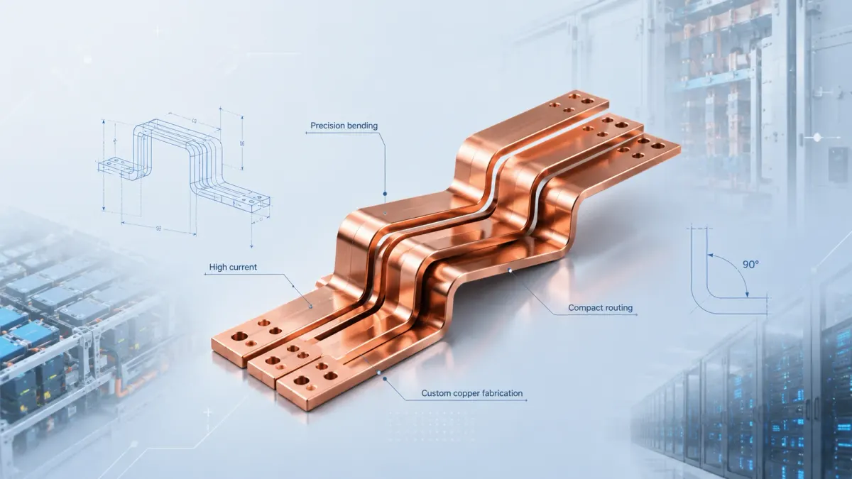
A folded bus bar is a copper busbar that has been cut, punched, and bent into a controlled three-dimensional shape. The word “folded” is practical rather than decorative. It means the bus bar is not limited to a flat strip or a simple straight link. It can turn around a module, rise above a component, step down to a terminal, avoid an insulation wall, bridge two levels of a cabinet, or connect points that do not sit on the same plane. For OEM buyers, this geometry can reduce wiring complexity, save installation space, improve assembly repeatability, and make the final equipment cleaner and easier to service.
JUMAI manufactures custom soft, hard, and braided copper busbars, with the main business focus on custom copper busbar fabrication. The company also supports deep-drawn components, stamping die customization, and related precision metal parts when a copper connection needs brackets, shielding covers, formed terminals, or custom tooling support. For a general overview of the busbar product range, buyers can start from JUMAI’s Custom Copper Busbars service page. For broader material and sourcing background, the Copper Busbar Guide is also a useful internal reference.
This article explains folded bus bars from a business and engineering perspective. It is written for purchasing managers, electrical engineers, mechanical designers, project managers, OEM sourcing teams, and system integrators who need custom copper parts that are not only conductive, but also manufacturable, repeatable, and easy to approve.
- Why folded bus bars matter in modern high-current assemblies
- What is a folded bus bar?
- The design logic: a folded bus bar is a controlled current path
- Material data buyers should understand before specifying folded bus bars
- Bending accuracy: the hidden difference between a copper strip and an engineered bus bar
- Bend radius, bend relief, and copper thickness
- Electrical design in plain English: resistance, voltage drop, and heat
- Contact design: why the terminal area is more important than it looks
- Insulation, clearance, and safety in folded copper busbar design
- Manufacturing process: from drawing review to finished folded bus bars
- Bending accuracy and inspection methods for production control
- Application scenarios: where folded bus bars create the most value
- Cost drivers: why the lowest copper price is not always the lowest project cost
- Common design mistakes in folded bus bar projects
- How JUMAI supports custom folded bus bar projects
- A practical folded bus bar specification template
- FAQ about folded bus bars
- Final recommendation: design the folded bus bar around the whole system
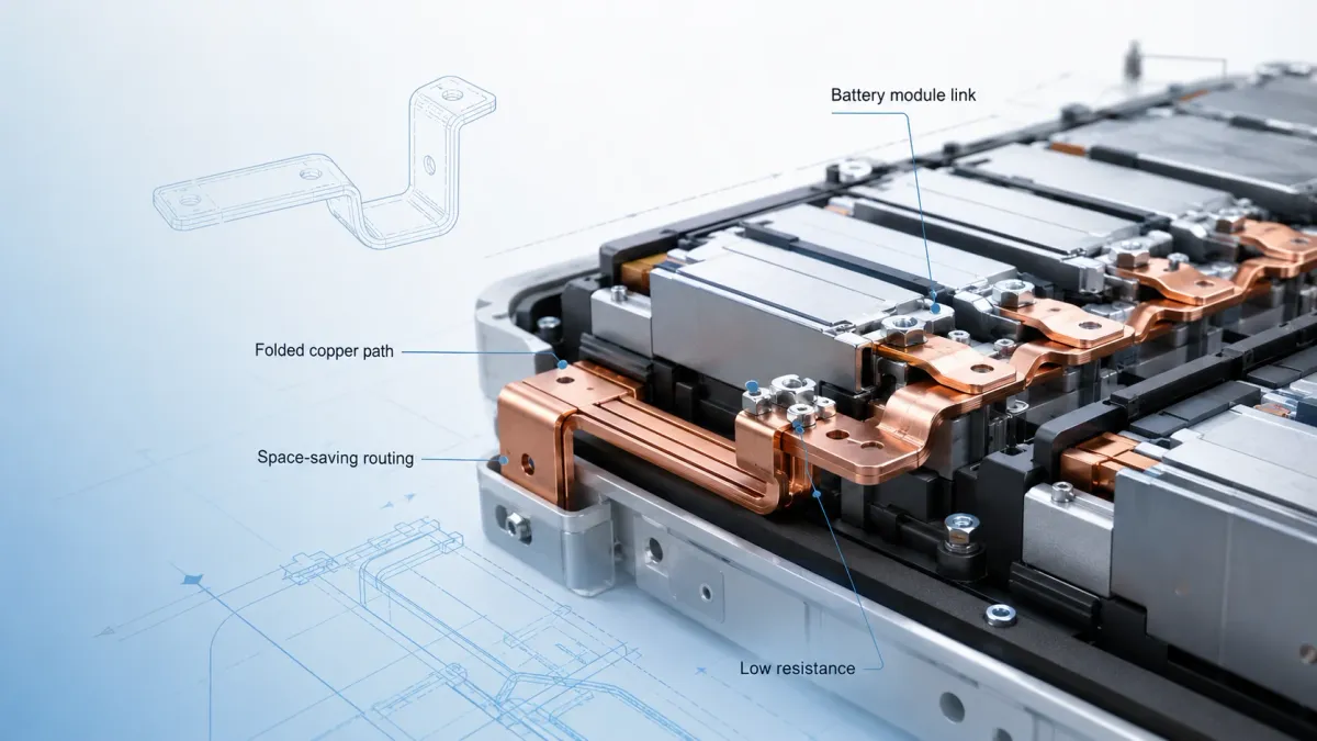
Why folded bus bars matter in modern high-current assemblies
The demand behind folded bus bars comes from a simple trend: electrical systems are carrying more power in less space. A cable can still be the right solution in many applications, but a cable bundle often requires large bending radius, manual routing, extra fixing accessories, and more installation labor. A folded copper bus bar, by contrast, gives the designer a defined current path. The part can be manufactured according to a drawing, inspected with fixtures, plated or insulated in selected areas, packed consistently, and installed in the same way every time.
This repeatability has commercial value. In a production line, a worker should not need to guess how a high-current cable should bend around a module. In a field service situation, a technician should not need to pull a cable into position under mechanical stress. In a cabinet design, the power path should not change from one assembly to the next because every installer routed the conductor slightly differently. Folded bus bars solve these problems by converting the conductor into an engineered part.
Industry growth also supports the need for better busbar design. The International Energy Agency reported that global electric car sales topped 17 million in 2024 and represented more than 20% of new car sales worldwide in its Global EV Outlook 2025. EV battery packs, high-voltage junction boxes, power distribution units, DC fast chargers, and traction inverter systems all need compact, reliable high-current conductors. In parallel, the IEA’s Energy and AI analysis estimated data center electricity consumption at about 415 TWh in 2024, or around 1.5% of global electricity consumption, with annual growth of about 12% over the previous five years. This expansion is pushing data center power systems toward higher density, better thermal control, and more repeatable power distribution hardware.
Folded bus bars fit this environment because they combine electrical performance with layout control. A copper conductor can be formed to follow a short, direct path from breaker to module, from battery cell group to pack terminal, from inverter DC link to power stage, or from busway to rack-level distribution. When the geometry is correct, the finished assembly can become smaller, safer, and more consistent.
What is a folded bus bar?
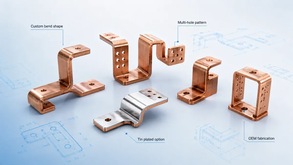
A folded bus bar is usually a rigid or semi-rigid copper conductor that has at least one bend. The bend may be a simple 90-degree fold, an offset step, a U-shape, a Z-shape, a multi-plane route, or a complex 3D profile with several bends and mounting holes. Most folded bus bars begin as copper sheet, strip, plate, or bar stock. The manufacturing route commonly includes blanking, cutting, punching, deburring, bending, cleaning, plating, insulation, marking, dimensional inspection, and packaging.
The simplest folded copper busbar may look like a flat bar with two holes and one right-angle bend. More advanced parts may include several features:
- multiple bends in different directions;
- mounting holes with controlled burr direction;
- slotted holes for assembly tolerance;
- embossed or formed areas for stiffness;
- offset terminal pads;
- tin, nickel, or silver plating in contact areas;
- heat-shrink, epoxy coating, PVC dipping, powder coating, or sleeving;
- insulation windows around holes and terminals;
- serial marking, polarity marking, or assembly identification.
In many projects, the best design is not purely rigid or purely flexible. A folded rigid copper bar may be used for the stable part of the power path, while a laminated flexible busbar or braided copper connector may be used where the assembly must absorb vibration or misalignment. JUMAI discusses this decision in Rigid Busbars vs Flexible Busbars and in its guide on what a flexible busbar is used for in high-current systems. For buyers, the important point is not to force every connection into one conductor type. The better approach is to match each section of the current path to the mechanical and electrical conditions it will face.
| Folded bus bar form | Common geometry | Typical use case | Main business value |
|---|---|---|---|
| Single-bend rigid bus bar | One 90-degree or angled bend between two terminal areas | Power cabinets, switchgear, charger modules, inverter terminals | Simple routing with repeatable assembly |
| Offset or step bus bar | Two bends creating a height change | Battery packs, BESS racks, compact cabinets, power distribution modules | Connects terminals on different planes without cable loops |
| Multi-plane folded bus bar | Three or more bends in a controlled 3D path | Dense equipment with obstacles, insulation partitions, stacked modules | Saves space and reduces installation uncertainty |
| Folded bus bar with plated terminals | Formed copper with tin, nickel, or silver on contact areas | Bolted joints, plated copper interfaces, mixed-metal contacts | Improves contact stability and corrosion resistance |
| Folded insulated bus bar | Bent copper with heat-shrink, epoxy, PVC, or coating | EV packs, power cabinets, high-voltage or compact low-voltage assemblies | Adds touch protection and reduces accidental short risk |
| Rigid-flex busbar assembly | Folded rigid section plus laminated or braided flexible section | Vibration zones, thermal expansion zones, module-to-module links | Balances accuracy, conductivity, and movement compensation |
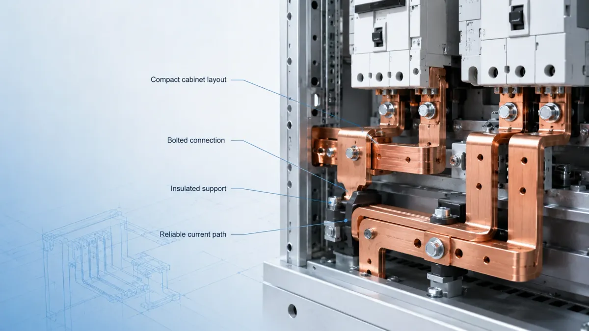
The design logic: a folded bus bar is a controlled current path
When a buyer requests folded bus bars, the first design question should not be, “How thick is the copper?” The better first question is, “What current path must this part control?” A folded busbar should be reviewed as an electrical, thermal, and mechanical component at the same time.
Electrically, the bus bar must carry rated current without excessive voltage drop or temperature rise. It must also survive overloads, short-duration peaks, and fault conditions according to the equipment design. The Copper Development Association’s busbar design resources explain that ampacity depends not only on conductor size, but also on heat dissipation, convection, surface condition, and emissivity. This matters because two copper bars with the same cross-sectional area can behave differently if one is installed in open air and the other is installed inside a compact sealed enclosure.
Thermally, a folded bus bar must remove heat from the current path. Copper has excellent conductivity, but it is not magic. When current passes through resistance, the conductor generates heat. If the bus bar is too thin, too narrow, too enclosed, poorly connected, or located near other heat sources, the temperature can rise beyond the design margin. IEC 61439-related low-voltage assembly guidance often focuses on temperature-rise verification because overheating can affect busbars, connections, functional units, and nearby insulation. Schneider Electric’s discussion of IEC 61439 temperature-rise verification gives a practical explanation of why this validation is important in electrical panels.
Mechanically, the bus bar must fit the assembly without forcing terminals out of position. This is where folded bus bars become more demanding than flat copper strips. The hole positions, bend angles, bend sequence, terminal flatness, bend radius, and springback compensation all influence whether the final part can be installed easily. A beautiful 3D model is not enough. The design must be producible in copper, with real tooling, real bend relief, real tolerance stack-up, and real inspection methods.
Commercially, a folded bus bar must be cost-effective at the expected production volume. A one-off prototype can be laser-cut and manually formed. A high-volume battery or power equipment project may need progressive tooling, bend fixtures, automated inspection, controlled plating windows, and repeatable packaging. If the part design ignores production volume, cost and lead time can become unstable later.
Material data buyers should understand before specifying folded bus bars
Most folded bus bars are made from high-conductivity copper such as C11000 or comparable T2 copper. JUMAI’s custom busbar service page states that the company uses high-purity T2/C11000 copper and can manufacture rigid, braided, and laminated flexible busbars for new energy vehicles, renewable energy, power distribution, and data center applications. For many custom copper busbar projects, C11000 is a practical balance of electrical performance, availability, cost, and formability.
Authoritative material references help buyers avoid vague specifications. ASTM B152/B152M covers copper sheet, strip, plate, and rolled bar, including C11000 and other copper UNS numbers. ASTM B187/B187M establishes requirements for copper conductor bars, rods, and shapes for electrical bus and general applications. These standards do not replace a project drawing, but they help define the material family, form, temper, and inspection expectations more professionally.
The Copper Development Association’s copper property information gives another useful data point: annealed copper at 20 degrees C is associated with electrical resistivity of about 1.7241 micro-ohm-centimeter and a temperature coefficient of electrical resistance of about 0.00393 per degree C for 100% IACS copper. These values, shown in CDA’s introduction to copper fact sheets, explain why copper remains a preferred conductor in high-current assemblies. Lower resistance means less heat for the same current, and high thermal conductivity helps spread heat away from local hot spots.
| Design data point | Practical value for folded bus bars | Typical engineering implication | Useful reference |
|---|---|---|---|
| Copper grade | C11000/T2 copper is widely used for high-conductivity busbar work | Good balance of conductivity, cost, availability, and formability | JUMAI Custom Copper Busbars |
| Copper purity | 99.9% copper is commonly specified for high-conductivity busbars | Helps reduce conductor resistance and supports stable electrical performance | JUMAI product information and copper material standards |
| Resistivity at 20 degrees C | About 1.7241 micro-ohm-centimeter for annealed copper | Used in voltage-drop and heat-generation calculations | Copper Development Association copper facts |
| Temperature coefficient | About 0.00393 per degree C for 100% IACS annealed copper | Resistance increases as temperature rises, so thermal design matters | Copper Development Association copper facts |
| Material form | Sheet, strip, plate, rolled bar, bar, rod, or conductor shape | Affects cutting, bending, tooling, flatness, and purchasing language | ASTM B152/B152M, ASTM B187/B187M |
| Surface condition | Bare copper, tin plating, nickel plating, silver plating, coating, or insulation | Influences oxidation resistance, contact behavior, cost, and safety | JUMAI tinned copper rigid busbar plating guide |
| Application growth signal | EVs and data centers are increasing demand for compact high-current conductors | Better busbar geometry supports high power density and reliable assembly | IEA Global EV Outlook 2025, IEA Energy and AI |
Bending accuracy: the hidden difference between a copper strip and an engineered bus bar
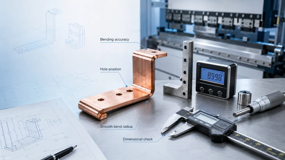
The most important manufacturing issue in folded bus bars is bending accuracy. A flat copper blank may pass incoming inspection, but after bending it becomes a 3D component. Each bend changes the final position of the holes, pads, and contact surfaces. When there are multiple bends, small angle errors can accumulate into a large assembly mismatch.
Bending accuracy includes several measurable items. Bend angle is the most obvious. A 90-degree bend that actually becomes 88.5 degrees may create a visible misfit. Bend position is equally important. If the bend line shifts by a small amount, the terminal pad may not reach the mounting location. Parallelism and perpendicularity matter when the bus bar must connect two flat surfaces. Terminal flatness matters because bolted electrical joints need good contact pressure. Hole location matters because the installer should not need to force screws through the part.
Copper also has springback. After a punch and die form the bend, the material tends to relax slightly. The amount depends on copper grade, temper, thickness, bend radius, bend angle, grain direction, tooling clearance, and forming method. A supplier that understands copper fabrication will compensate for springback in the tooling and process. This is one reason a folded bus bar should not be treated like a generic sheet metal part. Copper is softer and more conductive than many structural metals, but it also marks easily, work-hardens, and requires careful handling to protect contact surfaces.
For a simple part, the tolerance discussion may be straightforward. For a complex 3D folded busbar, JUMAI normally benefits from receiving both 2D drawings and 3D STEP or IGES files. The 2D drawing defines critical dimensions, tolerances, surface finish, plating, insulation, and inspection notes. The 3D file helps engineers review bend sequence, interference risk, and assembly envelope. This workflow is consistent with the manufacturing-route logic in JUMAI’s Copper Busbar Guide and with the engineering checklist used in JUMAI’s server rack power distribution bus bar guide.
Common commercial tolerance targets should be treated as starting points, not universal rules. A prototype for a power cabinet may accept a wider bend-angle tolerance than a high-volume battery module link that must fit into automated assembly equipment. Critical contact surfaces may need tighter flatness than non-contact routing areas. A hole used for loose mechanical mounting may allow a wider tolerance than a hole that locates a current-carrying terminal. The right supplier should help separate critical-to-function dimensions from normal manufacturing dimensions.
Bend radius, bend relief, and copper thickness
A folded bus bar design should define bend radius intentionally. A bend radius that is too sharp can create cracking, thinning, edge stress, or excessive hardening, especially when the copper is thick or hard temper. A bend radius that is too large may waste space and make the assembly less compact. The best bend radius is therefore not always the smallest possible radius. It is the smallest radius that can be produced repeatably without damaging the copper or causing assembly problems.
Bend relief is another design feature that many buyers overlook. If a bend begins very close to a wide section, hole, slot, step, or tab, the metal may distort near the bend. Relief notches or clearance features can help control deformation, but they must be designed so they do not create weak points, electrical bottlenecks, or insulation issues. For high-current folded bus bars, a relief cut is not only a mechanical detail; it can also affect current density and local heating.
Copper thickness affects almost every design decision. Thicker copper can carry more current and provide more mechanical stiffness, but it requires higher bending force, larger bend radius, stronger tooling, and more careful springback control. Thinner copper is easier to form and can be stacked or laminated for some applications, but it may need wider geometry or multiple layers to carry the required current. In EV batteries and BESS systems, laminated flexible busbars may be preferred when the connection must bend repeatedly or absorb movement. JUMAI’s battery busbar design guide gives more context for battery-focused conductor decisions.
For folded rigid bus bars, the design team should avoid treating thickness as the only current-capacity parameter. Width, length, installation orientation, surface area, contact resistance, enclosure temperature, neighboring heat sources, cooling airflow, and duty cycle all matter. A short wide bar may run cooler than a long narrow bar with the same cross-sectional area because it has a different heat path and surface area. A plated joint with stable contact pressure may perform better than a bare copper joint that oxidizes or loosens under vibration.
Electrical design in plain English: resistance, voltage drop, and heat
A folded copper bus bar carries current through a defined path. Every conductor has resistance. Copper has low resistance, but in high-current systems even small resistance can create measurable heat. The simple relationship is that heat generated in the conductor increases with the square of current. This means doubling the current does not merely double heat generation; it can produce four times the resistive heating if resistance remains the same.
Voltage drop is also important. A long, narrow busbar can reduce voltage at the load side. In low-voltage high-current equipment, voltage drop can affect efficiency, regulation, and heat balance. In high-voltage battery or power conversion systems, voltage drop may be less visible than insulation and clearance issues, but it still contributes to thermal performance and energy loss.
The copper cross-section is the starting point for resistance calculation. A wider or thicker conductor usually has lower resistance. However, folded bus bars are not just theoretical rectangles. Holes, slots, notches, narrowed sections, embossed features, bend deformation, contact interfaces, and plating choices can change real performance. A hole near a high-current path reduces local conductive area. A narrow neck between two wider sections can become a hot spot. A poorly controlled bolted joint can contribute more heat than the copper span itself.
This is why JUMAI recommends that buyers provide not only dimensions, but also current, voltage, duty cycle, ambient temperature, cooling condition, insulation requirement, and connection method. A drawing without electrical context can be manufactured, but it cannot be optimized. JUMAI’s broader copper bus bars for power distribution article discusses why busbar design affects efficiency, reliability, installation speed, and equipment layout.
For early quoting, a supplier can often estimate whether the proposed copper size is reasonable. For final approval, the system owner should verify thermal performance in the real equipment. This may include calculation, simulation, prototype testing, temperature-rise testing, or certified assembly testing depending on the product category. The supplier can manufacture a high-quality folded bus bar, but the complete electrical assembly must still be validated by the equipment designer or certified laboratory where required.
Contact design: why the terminal area is more important than it looks
Many folded bus bar failures are not caused by the middle of the copper span. They occur at the joints. The terminal area is where electrical, mechanical, and environmental requirements meet. If a bolted joint has poor flatness, incorrect torque, contamination, oxidation, insufficient contact area, or mismatch between metals, resistance can increase. Higher resistance generates heat. Heat can soften insulation, accelerate oxidation, reduce contact pressure, and create a cycle of worsening performance.
A good folded bus bar design defines the contact surface carefully. The drawing should show whether the contact area is bare copper, tin-plated, nickel-plated, silver-plated, masked from insulation, or coated after assembly. Tin plating is common because it helps protect copper against oxidation and supports stable contact in many industrial environments. Nickel may be used where higher temperature or diffusion barrier behavior is needed. Silver may be specified for demanding electrical contact performance, but it increases cost and should be used where the performance benefit is justified. JUMAI’s tinned copper rigid busbar plating guide provides practical context for choosing tin, nickel, or silver plating.
The terminal pad should also be flat enough for the joint. During bending, copper can distort, especially when the bend is near the hole. If the terminal area is not controlled, the installer may tighten the bolt but still fail to achieve uniform contact pressure. This is why terminal flatness, deburring, cleaning, and packaging all matter. Scratches, dents, and oxidation can reduce the quality perception of the part and may also affect contact behavior.
Hole design deserves similar attention. Round holes are common, but slotted holes can help compensate for assembly tolerance. However, slots should not be used to hide poor bend accuracy. They should be applied intentionally, with the current path and contact washer area in mind. Oversized or poorly located holes may reduce contact area or create local current crowding.
Insulation, clearance, and safety in folded copper busbar design
A folded copper busbar often passes near other conductors, metal housings, battery modules, PCB assemblies, cabinet walls, or human-accessible areas. The more compact the system, the more important insulation becomes. Insulation is not only a coating added at the end. It should be designed together with bend geometry, terminal windows, edge quality, heat rise, creepage, clearance, and assembly process.
Common insulation options include heat-shrink tubing, PVC dipping, powder coating, epoxy coating, wrapped insulation film, molded covers, insulating boots, and laminated structures. Each option has trade-offs. Heat-shrink can be cost-effective and flexible for many shapes. Epoxy coating can provide a clean appearance and good coverage when the geometry is suitable. PVC dipping can cover complex shapes but requires careful control of thickness and terminal masking. Custom covers may be useful when serviceability or high-voltage separation is important.
Clearance and creepage requirements depend on system voltage, pollution degree, altitude, insulation material, regulatory framework, and the overall equipment design. Folded bus bars can make these requirements easier or harder. A well-designed bend can keep the conductor away from a grounded wall. A poorly designed bend can bring a live edge too close to another metal part. This is why a supplier should review the busbar in the context of the assembly envelope, not only as an isolated copper part.
For enclosures, the International Electrotechnical Commission describes IEC 60529 IP ratings as a method for rating resistance of enclosures against dust and liquid intrusion. IP rating is not a busbar coating standard, but it affects the environment in which a folded busbar operates. A busbar inside a clean, dry cabinet faces different risks than one inside equipment exposed to moisture, conductive dust, vibration, or outdoor temperature swings.
In compact high-current equipment, insulation windows must be controlled carefully. The contact pad must remain free of coating where electrical contact is required. At the same time, coating should extend far enough to reduce accidental contact risk. Poor masking can create either weak electrical joints or exposed copper areas. For repeat production, masking fixtures and inspection standards should be defined early.
Manufacturing process: from drawing review to finished folded bus bars
Custom folded bus bars are usually built through a sequence of controlled steps. The exact process depends on thickness, quantity, geometry, plating, insulation, and inspection requirements, but the overall flow is predictable.
First, the supplier reviews the RFQ package. This should include drawings, 3D files, material requirements, current and voltage information, surface finish, insulation, quantity, annual forecast, assembly conditions, and any applicable standards. If only a photo or sample is available, reverse engineering may be possible, but a formal drawing is still needed before stable production.
Second, engineers review manufacturability. They check whether the bend radius is practical, whether holes are too close to bend lines, whether the bend sequence is possible, whether the part will collide with tooling, whether the terminal pads can remain flat, and whether plating or coating can be controlled. This DFM review is one of the most valuable services a custom copper fabricator can provide. A small change in bend position, relief notch, hole shape, or insulation boundary can prevent production problems later.
Third, the copper blank is produced. Depending on the project, this may involve shearing, laser cutting, CNC punching, stamping, or progressive die production. For prototypes and low-volume projects, flexible cutting methods can reduce tooling cost. For higher-volume projects, dedicated stamping tooling may reduce unit cost and improve repeatability. JUMAI’s article on stamping die basics is relevant when a folded bus bar or related copper part needs repeatable high-volume blanking and forming.
Fourth, the blank is deburred and cleaned. Burr direction is important because burrs can interfere with assembly, damage insulation, reduce creepage distance, or create sharp edges near other conductors. For current-carrying contact areas, surface cleanliness also affects plating and joint performance.
Fifth, the part is bent. Bending may be completed with press brake tooling, forming dies, dedicated fixtures, or staged operations. The process must control angle, position, sequence, and cosmetic marks. For multi-bend busbars, first-off inspection should verify not only individual bend angles but also final 3D geometry.
Sixth, the surface is finished. Some folded bus bars remain bare copper, but many are tin-plated, nickel-plated, silver-plated, coated, dipped, or heat-shrink insulated. The process may involve selective plating or masking to keep certain areas conductive and other areas protected. Plating thickness, adhesion, visual quality, and coverage should match the drawing and application.
Seventh, quality control verifies the part. Inspection may include dimensional measurement, hole position, bend angle, flatness, coating coverage, plating appearance, burr condition, conductivity-related checks, pull tests for attached terminals, and packaging inspection. For complex projects, checking fixtures can make inspection faster and more repeatable.
Finally, the parts are packed for shipment. Packaging is not a minor detail. Copper surfaces can scratch, oxidize, or deform if parts are stacked carelessly. Bent bus bars can also be damaged if heavy parts press against terminal areas or bends during transport. Good packaging protects the part and reduces incoming quality disputes.
Bending accuracy and inspection methods for production control
A reliable folded busbar project should define how accuracy will be measured. If the drawing only says “make according to sample,” inspection becomes subjective. If the drawing defines critical dimensions, tolerances, datum references, and measurement method, the buyer and supplier can make decisions based on evidence.
For simple parts, calipers, angle gauges, height gauges, and visual inspection may be enough. For complex parts, a coordinate measuring machine, optical measurement, 3D scanning, or dedicated go/no-go fixture may be needed. Production fixtures are especially useful when the part must fit a cabinet, battery module, or rack power assembly with limited clearance. The fixture can confirm whether all mounting points and terminal pads land in the correct position.
Critical-to-quality dimensions should be separated from normal dimensions. For example, a cosmetic edge length may not need tight control, while a terminal-to-terminal distance may decide whether the part fits the assembly. A mounting hole near a flexible bracket may allow more tolerance than a bolted electrical interface that must match a power module. Good tolerance strategy can reduce cost because it keeps tight tolerances where they matter and avoids over-specifying non-critical features.
Buyers should also consider bend sequence during design approval. A part may be possible to draw but difficult to bend because one bend blocks access to the next bend. A bend may require special tooling because a flange, offset, or previous bend interferes with the machine. When JUMAI reviews a 3D file, these issues can be identified before tooling or sample production. Early DFM feedback is much cheaper than changing a production tool after the first samples fail to fit.
| RFQ or drawing item | Why it matters for folded bus bars | Recommended buyer input |
|---|---|---|
| 2D drawing with tolerances | Defines acceptance criteria for dimensions, holes, bends, plating, and insulation | PDF or DWG with critical dimensions, tolerances, units, revision control |
| 3D model | Helps review bend sequence, collisions, assembly envelope, and fixture design | STEP or IGES file for complex folded shapes |
| Current and voltage | Needed to review cross-section, heat, insulation, clearance, and creepage | Rated current, peak current, voltage class, AC/DC condition, duty cycle |
| Operating environment | Affects plating, insulation, corrosion resistance, and vibration design | Ambient temperature, enclosure type, humidity, vibration, dust, cooling condition |
| Contact method | Determines terminal flatness, hole size, plating, washer area, and torque sensitivity | Bolt size, contact surface, mating material, torque requirement, plating preference |
| Bend requirements | Controls manufacturability and final assembly fit | Bend angle, inside radius, bend direction, bend line location, critical datum scheme |
| Surface finish | Affects conductivity, oxidation resistance, solderability, and contact quality | Bare copper, tin, nickel, silver, selective plating, coating, or insulation details |
| Production quantity | Influences tooling choice, unit cost, lead time, and inspection strategy | Prototype quantity, pilot order, annual forecast, target price, ramp schedule |
| Compliance target | Prevents late-stage redesign for certification or customer approval | IEC, UL, RoHS, REACH, customer standard, drawing standard, test method |
Application scenarios: where folded bus bars create the most value
Folded bus bars are most valuable when high current, limited space, and repeatable assembly meet in the same product. They may not be necessary for every connection, but they are often the cleanest solution when the conductor must do more than simply bridge two nearby terminals.
In EV battery packs, folded bus bars can connect modules, contactors, fuses, current sensors, service disconnects, and pack terminals. Space is limited, vibration is real, and the assembly must be consistent. Some connections may use laminated flexible busbars, while other pack-level conductors may use folded rigid copper with insulation. The supplier should understand both options because the best battery pack often uses several conductor styles together.
In BESS racks and cabinets, folded copper busbars can help connect battery modules, DC combiner sections, protection devices, and cabinet-level output terminals. BESS systems may have long service life expectations, thermal cycling, and maintenance requirements. Plated terminals and controlled insulation windows can improve assembly quality and reduce field service risk.
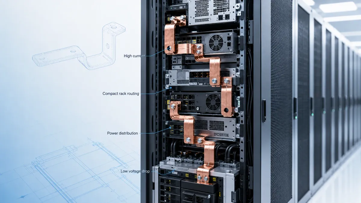
In data centers, power density is a central concern. Rack power distribution, busway interfaces, PDUs, UPS systems, and power conversion equipment all benefit from compact and repeatable conductors. JUMAI’s bus bar for server rack power distribution article explains why server rack power designs need careful review of current, voltage, thermal conditions, and application environment. Folded bus bars are especially useful where power must move vertically or horizontally through constrained cabinet geometry.
In switchgear and power distribution cabinets, folded bus bars can connect breakers, contactors, meters, bus compartments, and output terminals. IEC 61439 and related assembly requirements make thermal and mechanical verification important. The conductor must not only carry current; it must also fit safely within the assembly, maintain clearance, and support predictable temperature rise.
In renewable energy equipment, folded bus bars appear in solar inverters, wind power converters, combiner boxes, and energy storage interfaces. These systems often combine high current, outdoor or semi-outdoor environments, and long operation life. Plating, insulation, and enclosure protection should be selected together.
In industrial drives, welding equipment, charging equipment, and power electronics, folded bus bars can reduce inductance compared with long cable loops and improve layout control. In some cases, laminated busbars may be used for low-inductance DC links, while folded rigid bus bars handle input/output or cabinet-level current routing. The decision depends on frequency, switching behavior, current, thermal design, and cost target.
Cost drivers: why the lowest copper price is not always the lowest project cost
Folded bus bars look simple, so some buyers compare them only by copper weight and unit price. This can be misleading. The real cost of a folded busbar project includes material, cutting, bending, tooling, deburring, plating, insulation, inspection, packaging, quality documentation, engineering support, scrap risk, and potential redesign cost.
Material cost is visible, but process cost can be equally important. A bus bar with many holes, slots, and bends may require more machine time. A tight bend radius may require special tooling. A multi-plane part may need a dedicated forming fixture. A selective plating design may need masking. An insulated part may require careful terminal window control. A high-volume project may benefit from stamping die investment, while a low-volume project may be better served by flexible cutting and CNC bending.
Tolerance also affects cost. Tight tolerances are sometimes necessary, but they should be applied intelligently. If every dimension is specified with unnecessary tight control, the supplier may need slower inspection, additional fixtures, higher scrap allowance, or more expensive tooling. If critical tolerances are not defined, the parts may be cheap but difficult to assemble. The best commercial result usually comes from clear critical dimensions, practical general tolerances, and early communication between buyer and supplier.
Plating and insulation are another cost driver. Tin plating may be practical for many applications, while silver plating should be justified by contact performance or customer requirement. Full insulation may be required for safety, but unnecessary coating over non-critical areas may increase cost without improving function. Good design controls where copper must be exposed and where it must be protected.
Packaging can also influence cost and quality. If parts are heavy, bent, plated, and cosmetic, protective packaging may be required. Poor packaging can create scratches, bent terminals, or oxidation complaints. For international projects, packaging should protect the parts through long transport, warehouse handling, and incoming inspection.
Common design mistakes in folded bus bar projects
One common mistake is placing holes too close to bend lines. This can distort the hole, reduce terminal flatness, or create cracks near the bend. If the hole must be near the bend, the design may need a larger bend radius, relief, different bend sequence, or special tooling.
Another mistake is ignoring burr direction. A burr facing an insulation layer, mating surface, or nearby conductor can cause problems. The drawing should define burr direction or deburring requirements when they matter. For high-current contact surfaces, edge quality and surface cleanliness are not optional details.
A third mistake is designing a very narrow neck between wider copper sections. The wide sections may look strong, but the narrow neck can become the real current bottleneck. Current density rises in the narrow area, and local heating can increase. Holes and notches should be placed away from the main current path when possible.
A fourth mistake is using cable thinking for a folded copper part. Cable routing can absorb some assembly tolerance because the cable is flexible. A rigid folded bus bar cannot. The part must fit based on controlled geometry. If the equipment has large assembly tolerance, the design may need slots, a flexible busbar section, a braided connector, or an intentional compliant joint.
A fifth mistake is coating the wrong area. Insulation should not cover electrical contact surfaces unless the coating is removed later by a controlled process. At the same time, exposed copper edges near other conductive parts can reduce safety margin. Masking windows should be clearly defined in the drawing.
A sixth mistake is approving a prototype without considering mass production. A technician can manually adjust a prototype busbar, but production parts should not depend on manual correction. If the project is expected to scale, the supplier should discuss fixtures, tooling, inspection method, and process capability early.
How JUMAI supports custom folded bus bar projects
JUMAI is positioned for buyers who need custom copper busbars rather than only catalog strips. The company’s core capability includes soft, hard, and braided copper busbars, with in-house support for punching, bending, plating, insulation, and CAD-based customization. When the project requires related metal parts, JUMAI also offers precision deep drawn components and stamping die support, which can be useful for shields, housings, brackets, terminals, covers, or forming tools used around the busbar assembly.
For a folded bus bar project, JUMAI can support several stages. During inquiry, the team reviews the drawing, 3D file, current requirement, voltage, insulation, plating, quantity, and application environment. During DFM, engineers check bend radius, hole position, bend sequence, terminal flatness, plating windows, and manufacturability. During prototyping, samples can be produced for dimensional and assembly review. During production preparation, JUMAI can define fixtures, process flow, plating or insulation control, and packaging. During mass production, quality control helps keep the copper geometry stable from batch to batch.
This is especially helpful for global buyers who need supplier feedback before committing to a final drawing. A buyer may know the equipment layout but not the best copper forming method. JUMAI can review whether a folded rigid busbar, laminated flexible busbar, braided copper connector, or mixed rigid-flex structure is more suitable. This approach reduces the risk of ordering a part that looks correct on paper but fails in assembly.
JUMAI is also useful when a project combines electrical and mechanical metalwork. For example, a data center power module may need folded copper bus bars, stamped brackets, deep-drawn shielding covers, and custom tooling. An EV battery pack may need insulated folded conductors, braided links, plated terminals, and formed protective parts. Having copper busbar and metal forming knowledge in one supplier can simplify communication and shorten development time.
A practical folded bus bar specification template
A good specification does not need to be overly complicated, but it should remove ambiguity. The following template can be adapted for an RFQ or drawing note.
Part name: Custom folded copper bus bar for [application].
Material: C11000/T2 copper, temper to be confirmed according to bending and mechanical requirements.
Thickness and width: Define nominal copper thickness, width, and any local narrowed sections.
Electrical requirement: Rated current, peak current, voltage, AC/DC, duty cycle, expected ambient temperature, and cooling condition.
Geometry: Provide 2D drawing with bend angles, bend directions, inside bend radius, hole sizes, hole locations, slots, datums, and critical dimensions. Provide 3D STEP or IGES file for complex folded shapes.
Surface finish: Bare copper, tin plating, nickel plating, silver plating, selective plating, or other finish. Define plating areas and non-plated areas.
Insulation: Heat-shrink, PVC dipping, epoxy, powder coating, sleeve, cover, or no insulation. Define terminal windows, coating thickness target, color, and any inspection requirement.
Contact areas: Define contact surface flatness, plating, burr direction, washer area, and any torque-related requirement.
Quality control: Define key dimensions, bend angle tolerance, hole tolerance, terminal flatness, visual standard, coating inspection, and sample approval process.
Packaging: Define whether parts require individual protection, anti-oxidation packaging, separators, labels, or special export cartons.
Standards and compliance: List any applicable customer standard, IEC, UL, ASTM, RoHS, REACH, or product certification requirement.
This level of information helps the supplier quote more accurately and helps the buyer compare suppliers on real capability rather than only price.
FAQ about folded bus bars
Are folded bus bars the same as rigid busbars?
Not exactly. A folded bus bar is often a type of rigid busbar, but the term emphasizes the formed geometry. A rigid busbar may be flat and straight, while a folded bus bar has one or more bends to fit a specific 3D path. Some projects also combine folded rigid sections with flexible or braided sections.
Why use a folded bus bar instead of a cable?
A folded bus bar provides a repeatable current path, controlled geometry, compact routing, and easier inspection. Cables are flexible, but they may require more space, larger bend radius, manual routing, and extra fixing accessories. In production equipment, folded copper busbars can reduce assembly variation.
What material is commonly used for folded bus bars?
High-conductivity copper such as C11000 or T2 copper is commonly used. The final material and temper should be selected according to current, bending, stiffness, plating, and cost requirements. Some projects may use oxygen-free copper or other copper alloys when the application requires it.
What drawings are needed for a custom folded bus bar?
A 2D drawing is essential because it defines tolerances, holes, bends, material, plating, insulation, and inspection requirements. A 3D STEP or IGES file is strongly recommended for complex folded shapes because it helps review bend sequence and assembly envelope.
How tight can the bending tolerance be?
The answer depends on copper thickness, bend radius, temper, part size, tooling, and inspection method. Many commercial folded busbar projects use practical bend-angle targets such as plus or minus 0.5 to 1 degree for normal formed parts, but critical applications may require project-specific controls and dedicated fixtures. The supplier should confirm feasible tolerances after reviewing the drawing.
Should contact areas be plated?
Often yes, especially where oxidation resistance and stable contact behavior are important. Tin plating is common for many industrial busbar joints. Nickel or silver may be used in more demanding conditions. The right choice depends on mating material, temperature, environment, cost, and customer standard.
Can folded bus bars be insulated after bending?
Yes. Common options include heat-shrink tubing, epoxy coating, PVC dipping, powder coating, and custom covers. The design should clearly define terminal windows and areas that must remain free of insulation.
Are folded bus bars suitable for EV battery packs?
Yes, folded copper busbars can be used in EV battery packs, especially for stable pack-level or module-level connections. However, areas exposed to vibration, thermal expansion, or assembly movement may require laminated flexible busbars or braided connectors. JUMAI can review which structure is more suitable for each connection.
Can JUMAI make prototypes before mass production?
Yes. JUMAI can review drawings, produce samples, inspect dimensions, and provide manufacturing feedback before mass production. For high-volume parts, the prototype stage can also help decide whether dedicated tooling or checking fixtures are needed.
What information should be included when requesting a quote?
Send the drawing, 3D file if available, quantity, material, thickness, current, voltage, plating, insulation, application environment, and any standards or test requirements. If the design is not finalized, send the available layout and functional requirements so JUMAI can provide DFM suggestions.
Final recommendation: design the folded bus bar around the whole system
Folded bus bars are valuable because they turn a high-current connection into a controlled, inspectable, and repeatable component. They are not only pieces of bent copper. They influence heat rise, voltage drop, contact reliability, assembly speed, maintenance access, insulation strategy, and equipment layout. In high-power industries such as EV batteries, BESS, data centers, renewable energy, power distribution, and industrial equipment, this level of control can directly affect commercial success.
The best folded bus bar design starts with the system requirement. Define the current path, electrical load, thermal condition, mechanical tolerance, insulation boundary, contact method, and production volume before locking the copper geometry. Then work with a supplier that understands copper behavior, bending accuracy, plating, insulation, tooling, and quality control.
For buyers who need custom folded bus bars, JUMAI can support rigid copper busbars, laminated flexible busbars, braided copper connectors, plated terminals, insulated conductors, and related precision metal parts. Share your CAD drawings, samples, application conditions, and target quantity with the JUMAI engineering team. A better folded bus bar is not only a better-looking part. It is a better power path, a better assembly process, and a better foundation for long-term equipment reliability.