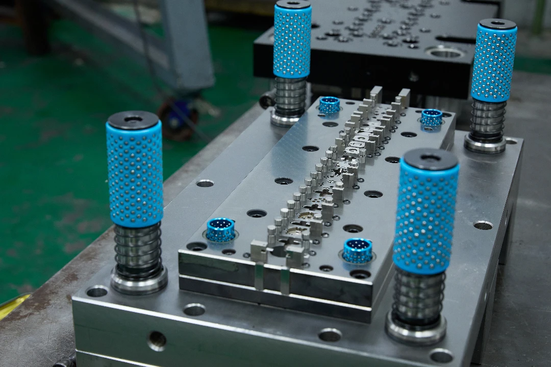
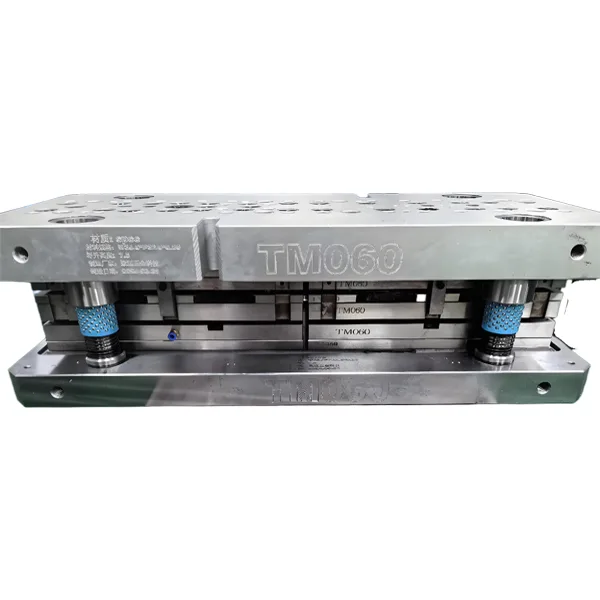
In the high-stakes world of precision manufacturing, the stamping die is the heartbeat of production. Whether we are producing complex Deep-Drawn Components or manufacturing high-conductivity Precision Copper Busbars here at JUMAI TECH, the integrity of the tooling dictates the quality of the final part. A stamping die is not merely a consumable tool; it is a sophisticated asset that represents a significant capital investment. When a die fails, it does not just halt a machine; it disrupts the supply chain, increases scrap rates, and erodes profit margins.
Having spent decades in the metal forming industry, I have witnessed firsthand that the difference between a profitable run and a logistical nightmare often comes down to how well an organization understands its tooling. It is not enough to simply react to problems as they arise. To maintain competitiveness in a global market, manufacturers must adopt a proactive stance toward stamping die health. This guide provides an exhaustive analysis of why dies fail and how a rigorous preventive maintenance program can extend tool life, ensure part consistency, and optimize operational efficiency.
Table of Contents
The Anatomy of Stamping Die Wear and Life Expectancy
To understand failure, one must first understand the life expectancy of a stamping die. A die does not degrade in a linear fashion; rather, it follows a “bathtub curve” of failure probability. Initially, there is a break-in period where minor imperfections are smoothed out. This is followed by a steady-state period of normal wear, which constitutes the majority of the tool’s useful life. Finally, the tool reaches a wear-out phase where dimensions drift rapidly, and catastrophic failure becomes imminent.
The lifespan of a die is heavily influenced by the material being stamped. For instance, stamping soft aluminum or copper for our busbar applications induces different wear patterns compared to stamping high-strength low-alloy (HSLA) steels. According to data from the Precision Metalforming Association, the increased use of Advanced High-Strength Steels (AHSS) in automotive applications has reduced die life by up to 40% in facilities that failed to upgrade their tool steel selection or coating technologies. Understanding these interactions is the first step toward mitigation.
Furthermore, the concept of “die life” is often calculated in millions of hits, but this metric is deceptive if not paired with part quality data. A die might physically survive 5 million hits, but if the burr height on the last 1 million parts exceeds tolerance, the die effectively “failed” long before it broke. Therefore, we define die failure not just as breakage, but as the point where the tool can no longer produce parts to specification at the required run rate.
Primary Categories of Stamping Die Failure
When we analyze a compromised stamping die, the root cause usually falls into one of several distinct tribological categories. Recognizing the specific “signature” of the failure is crucial because the remedy for chipping is vastly different from the remedy for galling. A misdiagnosis here can lead to expensive, ineffective repairs that waste both time and money.
Abrasive Wear
Abrasive wear is perhaps the most common and predictable form of tool degradation. It occurs when hard particles—either contained within the sheet metal itself or introduced as environmental contaminants—gouge the surface of the die components. As the punch enters and retracts from the material, these hard particles act like microscopic sandpaper, slowly eroding the cutting edges and forming surfaces.
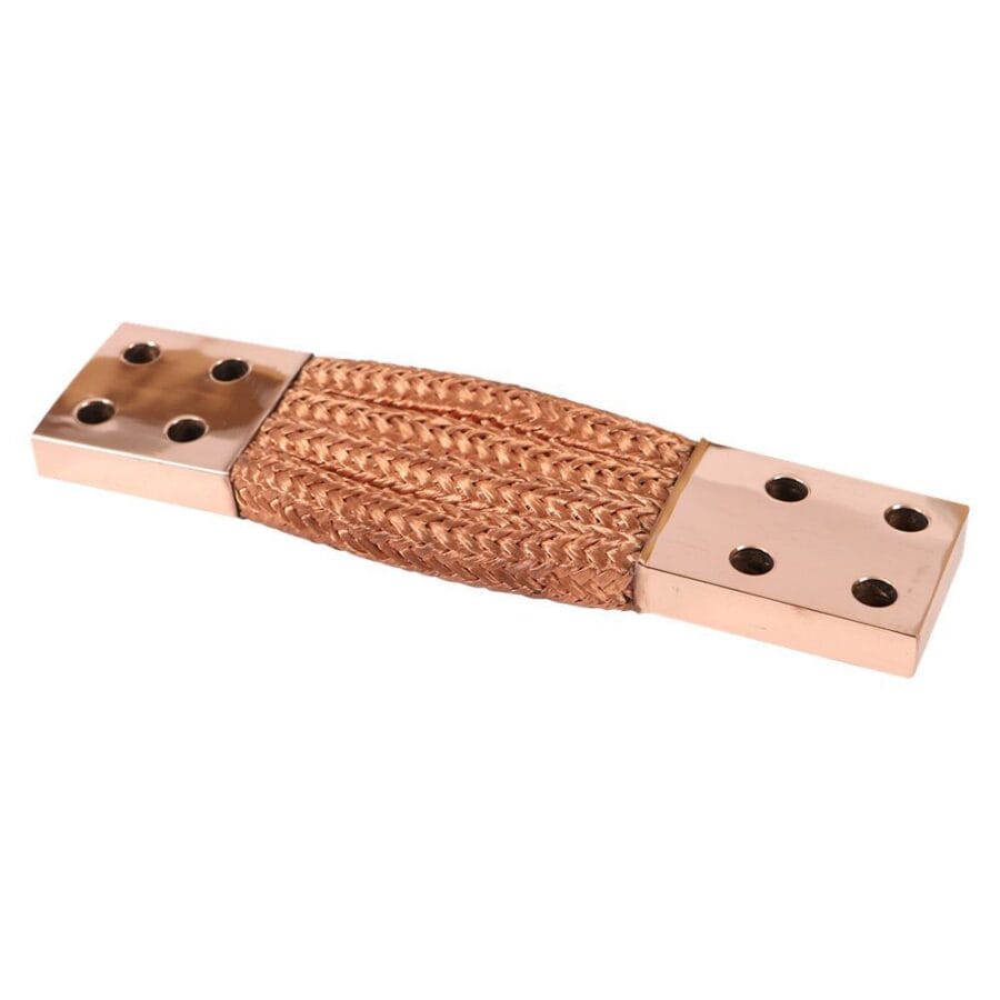
In the context of stamping copper busbars, abrasive wear can be surprisingly aggressive. While copper is soft, the copper oxide layer found on some raw materials is extremely hard and abrasive. Over time, this results in the rounding of punch edges. As the edge rounds, the force required to fracture the metal increases, leading to higher tonnage requirements and larger burrs on the finished part.
Adhesive Wear and Galling
Adhesive wear, commonly known as galling or cold welding, is a catastrophic failure mode that plagues high-speed stamping operations. This phenomenon occurs when the pressure between the tool and the workpiece becomes so great that the lubricating film breaks down, allowing direct metal-to-metal contact. At the microscopic level, the workpiece material welds itself to the punch or die button, and as the tool moves, it tears these welds apart.
The result is a buildup of workpiece material on the tool. Once galling begins, it escalates exponentially. The accumulated material changes the effective dimensions of the punch, reducing clearance and increasing friction heat. For deep-drawn components, galling leads to severe scoring on the side walls of the part, rendering it cosmetically and functionally unacceptable.
Table 1: Visual Identification of Wear Modes
| Wear Mode | Visual Characteristic | Primary Cause | Recommended Immediate Action |
| Abrasive Wear | Shiny, polished appearance; rounded cutting edges; uniform dimensional loss. | Hard particles in material; lack of lubrication viscosity. | Regrind tool; switch to higher vanadium carbide tool steel (e.g., CPM 10V). |
| Adhesive Wear (Galling) | Rough, torn surface; material pickup (chunks of workpiece welded to tool). | Lubrication failure; insufficient clearance; excessive heat. | Polish off pickup; apply PVD coating (TiCN or CrN); improve lube delivery. |
| Chipping | Jagged, irregular fractures on the cutting edge. | Impact shock; tool material too brittle; misalignment. | Check alignment; switch to tougher steel (e.g., S7 or DC53); reduce impact speed. |
| Plastic Deformation | Mushrooming of the punch tip; sinking of the die face. | Compressive yield strength of tool steel exceeded by stamping force. | Upgrade to High-Speed Steel (HSS) or Carbide; increase contact surface area. |
Chipping and Gross Fractures
Unlike wear, which is gradual, chipping and fracturing are sudden events. Chipping typically occurs at the cutting edge and is often caused by a misalignment between the punch and the die matrix. When the clearance is uneven, the side with the tighter clearance experiences excessive lateral forces, causing the edge of the punch to flake off.
Gross fractures, where a tool splits entirely, are usually related to heat treatment errors or catastrophic overloads. For example, if a slug is pulled back up to the die surface (a phenomenon known as “slug pulling”) and the tool hits it on the next stroke, the result is a “double hit.” The incompressible nature of the double layer of metal creates a pressure spike that can shatter even the most robust tool steels.
Fatigue Failure
Fatigue is the silent killer of stamping die components. It occurs due to the cyclic loading and unloading of the tool. Even if the stress applied in a single hit is well below the yield strength of the material, millions of cycles can initiate microscopic cracks at stress risers—such as sharp corners, complex geometries, or surface scratches from poor grinding.
Over time, these micro-cracks propagate until the remaining material can no longer support the load, leading to a sudden snap. This is particularly prevalent in forming dies used for deep-drawn components, where the forces are sustained over a longer portion of the stroke compared to simple blanking operations.
The Critical Role of Cutting Clearance

One of the most frequent technical errors I encounter when consulting for clients is improper cutting clearance. Clearance is the gap between the punch and the die button. It is not an arbitrary number; it must be calculated precisely based on the material type and thickness.
Calculating Optimal Clearance
If the clearance is too tight, the secondary shear cracks from the punch and die do not align. This forces the punch to push through more material, generating immense heat and side-thrust, which accelerates abrasive wear and increases the risk of galling. Conversely, if the clearance is too loose, the material tends to roll over rather than shear cleanly, resulting in large burrs and excessive deformation around the hole.
For standard steel, a clearance of 10% of the material thickness per side is a common starting point. However, for the precision copper busbars we manufacture at JUMAI TECH, we often adjust clearances to accommodate the ductility of copper. Copper tends to “grab” the punch, so slightly larger clearances or specific tapered die geometries are sometimes necessary to prevent stripping issues.
Technical Note: Always verify clearance after sharpening. When a die with a tapered relief is sharpened, the opening size increases, potentially altering the clearance ratio. Shimming or replacing die buttons may be necessary to maintain the original engineering specifications.
Material Selection: The Foundation of Die Longevity
The choice of tool steel is a fundamental variable in the equation of die life. Using the wrong steel for the application is a guarantee of premature failure. In the past, O1 and D2 steels were the industry standards. While D2 is still a workhorse, modern high-volume stamping demands more advanced metallurgy.
High-Speed Steels and Powder Metallurgy
For high-volume runs of deep-drawn components, we often transition from D2 to particle metallurgy (PM) steels like CPM M4 or CPM 10V. These materials are produced by atomizing molten steel into powder and then compacting it. This process ensures a uniform distribution of carbides, unlike conventional casting which can result in carbide segregation (clumps).
Uniform carbide distribution means the steel is tougher and more grindable, even at high hardness levels (60-64 HRC). For applications involving stainless steel or other work-hardening alloys, cemented carbide (Tungsten Carbide) is the ultimate solution. While carbide is brittle and expensive, its wear resistance is unmatched. At JUMAI TECH, we utilize carbide inserts in critical high-wear areas of our dies to ensure that our millionth part is as precise as our first.
Learn more about Tool Steel Metallurgy from MatWeb
Heat Treatment and Surface Modifications
Even the best tool steel will fail if heat treated incorrectly. The heat treatment process dictates the balance between hardness (wear resistance) and toughness (impact resistance). A common failure is “retained austenite.” If the quenching process is not sufficiently rapid or cold, some austenite (a soft phase of steel) may not transform into martensite (the hard phase).
Under the stress of stamping, this unstable retained austenite can transform into untempered martensite, which is extremely brittle. This causes the tool to grow slightly in size, leading to internal stresses and eventual cracking. To prevent this, we advocate for cryogenic treatment—freezing the steel to -300°F (-185°C)—as part of the tempering process to ensure full conversion to martensite.
Advanced Coatings
In modern stamping, coatings are not optional; they are essential.
- TiN (Titanium Nitride): The classic gold coating. Good for general purpose, but less effective for high-strength steels.
- TiCN (Titanium Carbonitride): Harder and with a lower coefficient of friction than TiN. Excellent for preventing galling in stainless steel stamping.
- TD (Thermal Diffusion): A process where vanadium carbide is diffused into the surface of the steel. This creates an incredibly hard surface layer that peels less than PVD coatings, making it ideal for forming dies in high-stress applications.
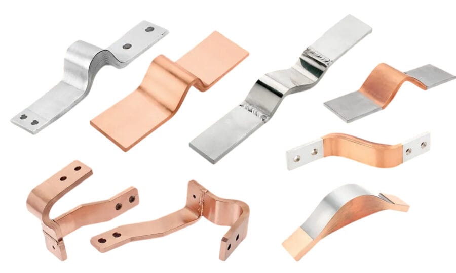
Deep-Drawn Components: Specific Failure Challenges
Deep drawing—the process of pulling a metal blank into a die to form a hollow shape—presents unique challenges compared to standard cutting. The primary failure mode here is not just tool wear, but flow failure.
If the friction between the blank holder and the material is too high, the metal will tear. If it is too low, the metal will wrinkle. The stamping die used for deep drawing must be polished to a mirror finish (often RA 2 or better) to facilitate material flow. Any scratch on the die radius acts as a brake, restricting flow and causing the part to split.
Furthermore, thermal cycling is a major issue in deep drawing. The friction generates significant heat, which causes the die components to expand. If the guide pins and bushings are not designed with thermal expansion in mind, the die set can seize up. At JUMAI TECH, we utilize high-performance bronze alloy bushings with graphite plugs to ensure lubrication is maintained even when thermal expansion reduces running clearances.
Preventive Maintenance: A Strategic Approach
Preventive Maintenance (PM) is the practice of servicing a stamping die based on data, rather than waiting for a breakdown. A robust PM program transitions a company from “firefighting” mode to “planning” mode.
The Data-Driven Maintenance Schedule
The key to PM is determining the “hit count” interval. This is done by tracking the die’s performance over time. If a die historically starts producing burrs at 100,000 hits, the PM should be scheduled at 80,000 hits.
Table 2: Standard Preventive Maintenance Protocol
| Frequency | Task Description | Objective |
| Daily / Shift Start | visual inspection of last part produced; check lubrication levels; verify scrap chute is clear. | Detect immediate issues like slug pulling or broken punches before full production starts. |
| Weekly (or every 50k hits) | Clean die set; inspect springs and nitrogen cylinders for pressure loss; check guide pillars for scoring. | Ensure mechanical functionality of the die set. |
| Interval (e.g., 100k hits) | Sharpen cutting edges (remove 0.002″ – 0.005″); demagnetize tool steel; inspect strippers for flatness. | Restore cutting edge to “like new” condition to minimize tonnage and wear. |
| Major Overhaul (1M hits) | Replace high-stress springs; replace guide bushings; re-coat forming sections (PVD/TD); exhaustive dimensional check. | Reset the fatigue life of consumable components to prevent catastrophic failure. |
Sharpening Best Practices
Sharpening is more than just grinding the top off a punch. It is an art. Using the wrong grinding wheel or feed rate can burn the steel, effectively re-tempering the surface and making it soft. This “grind burn” is invisible to the naked eye but will cause the edge to fail almost immediately upon return to production.
Operators must use soft bond wheels with copious amounts of coolant. Furthermore, after grinding, it is critical to stone the edge. A razor-sharp edge is actually prone to chipping; a microscopic radius (honed edge) adds strength to the cutting tip and significantly extends tool life.
The Role of Lubrication in Failure Prevention
Lubrication is the lifeblood of the stamping process. It provides a barrier between the tool and the workpiece, reduces friction, and carries away heat. However, using the “wrong” lubricant is a common cause of stamping die failure.
For example, a light vanishing oil might be perfect for stamping thin electronics parts, but it will fail instantly in a heavy-duty deep draw operation, leading to galling. Conversely, using a heavy chlorinated oil on copper parts can lead to staining and corrosion if not cleaned immediately.
Modern synthetic lubricants offer high film strength without the environmental baggage of chlorinated oils. We must also consider the application method. A drip system is often inconsistent. Spray, roller, or mist systems ensure a uniform film thickness. If a die fails repeatedly in the same location, check the lube nozzle alignment—often, the failure is simply due to a dry spot.
Sensors and Smart Dies: The Future of Maintenance
The industry is moving toward “Smart Dies.” By embedding piezoelectric force sensors and acoustic emission sensors within the die shoe, we can monitor the stamping process in real-time.
These sensors can detect:
- Misfeeds: Preventing the die from closing on a half-fed strip.
- Slug Stacking: Detecting the slight pressure increase caused by slugs not ejecting.
- Wear Trends: Noting a gradual increase in tonnage required to make a hit, indicating the edges are dulling.
At JUMAI TECH, we are integrating these technologies into our high-speed lines. This allows us to perform “Predictive Maintenance” rather than just Preventive Maintenance. The die tells us when it is tired, rather than us guessing based on a calendar.
Troubleshooting: A Step-by-Step Guide
When a die fails, a systematic approach is required to identify the root cause.
- Stop and Preserve: Do not clean the die immediately. Examine the “crime scene.” Look at the strip skeleton, the last part produced, and the scraps. They tell the story.
- Check the Press: Is the press bed parallel? is the ram gibbing loose? Sometimes the die is blamed for a press problem.
- Inspect the Strip: Did the material hardness or thickness change? A coil of steel at the upper limit of the hardness specification can destroy a die designed for softer stock.
- Look for Magnetism: Over time, dies become magnetized, causing slugs to stick to the punch. A simple pass with a gauss meter can confirm this.
Economic Implications of Die Maintenance
Ignoring maintenance is expensive. The cost of sharpening a die is perhaps $500. The cost of a catastrophic crash—including a new die section ($5,000), press downtime ($300/hour), and missed delivery penalties—can easily exceed $20,000.
Furthermore, maintained dies run faster. A dull die generates more heat and requires the press to run slower to avoid overheating. Sharp, coated dies allow for maximum strokes per minute (SPM), directly impacting the bottom line. For our clients purchasing Precision Copper Busbars, this efficiency translates into competitive pricing and reliable lead times.
JUMAI TECH: Your Partner in Precision
At JUMAI TECH (Deep Draw Tech), we do not just sell parts; we sell the assurance of quality. Our deep understanding of stamping die failure modes and our rigorous adherence to preventive maintenance protocols ensures that every component leaving our facility meets the highest standards of precision.
Whether you require intricate Deep-Drawn Components or robust Precision Stamping Dies and accessories, our team applies the technical depth discussed in this article to every project. We understand that in manufacturing, reliability is the ultimate currency.
By controlling the variables of material, lubrication, clearance, and maintenance, we turn the volatile process of metal stamping into a predictable science.
Frequently Asked Questions (FAQ)
Q1: How often should I sharpen my stamping die?
A: It depends on the material and tonnage, but a general rule is to sharpen when the burr height reaches 50% of the maximum allowable tolerance. Do not wait for the burr to reach the limit, as this requires removing more stock from the die to restore the edge.
Q2: What is the best coating for stamping stainless steel?
A: TiCN (Titanium Carbonitride) is excellent, but TD (Thermal Diffusion) or CVD (Chemical Vapor Deposition) coatings are superior for heavy-forming applications due to their extreme hardness and adhesion.
Q3: Why are my punches chipping?
A: Look for misalignment or excessive snap-through shock. If alignment is perfect, the tool steel might be too brittle (e.g., D2). Consider switching to a tougher matrix steel or checking if the heat treatment left retained austenite.
Q4: Can JUMAI TECH help design a maintenance plan for dies you didn’t build?
A: While we specialize in our own production, our engineering team is always open to consulting on tooling challenges, particularly for clients utilizing our precision components.
Q5: What causes slug pulling?
A: Slug pulling is caused by the suction of the punch withdrawing or oil surface tension. It can be prevented by using ejector pins in the punch (spring-loaded pins), adding a shear angle to the punch face, or using a “bell-mouthed” die button design.
Contact JUMAI TECH today to discuss your precision manufacturing needs. Let us put our expertise to work for you.