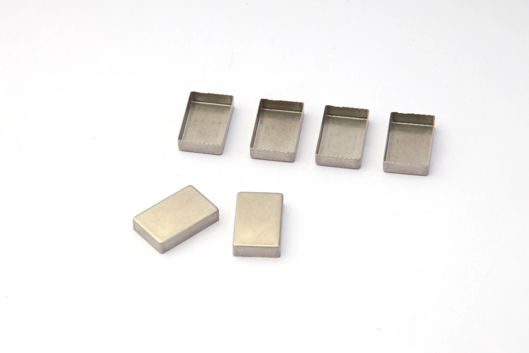
In the world of precision manufacturing, few processes offer the versatility, speed, and structural integrity of deep drawn metal stamping. Whether we are engineering intricate shielding cans for electronics, heavy-duty automotive housings, or the custom Precision Copper Busbars that have become a hallmark of JUMAI TECH, the deep drawing process is essential. However, it is also a process unforgiving of poor design. Unlike simple bending or laser cutting, deep drawing forces metal to flow, stretch, and compress simultaneously. A design that looks perfect in CAD can easily fail on the shop floor, resulting in split parts, wrinkled flanges, or costly tooling modifications.
At JUMAI TECH, we have spent years bridging the gap between theoretical design and practical manufacturability. We have seen firsthand how minor adjustments to a radius or a wall thickness specification can save our global clients thousands of dollars and reduce lead times by weeks. This guide is not just a list of rules; it is a compilation of engineering wisdom derived from producing millions of Deep-Drawn Components. By understanding the mechanics of material flow and adhering to specific design principles, you can ensure your parts are not only functional but also cost-effective and reliable to manufacture at scale.
Table of Contents
Understanding the Physics of Deep Drawn Metal Stamping
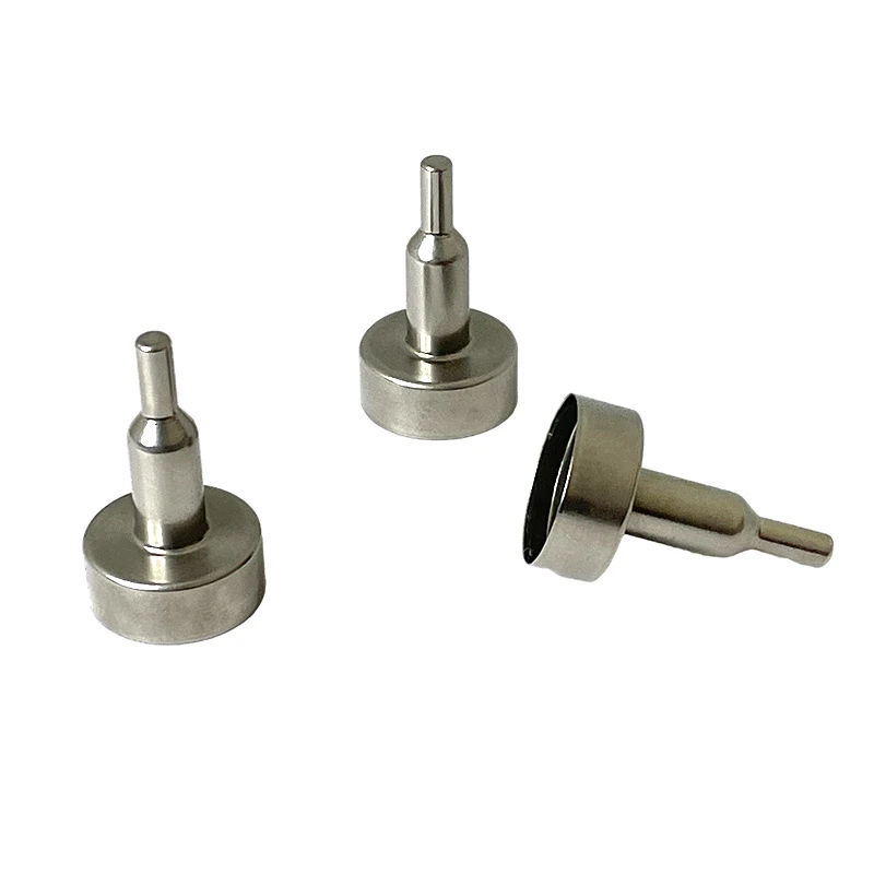
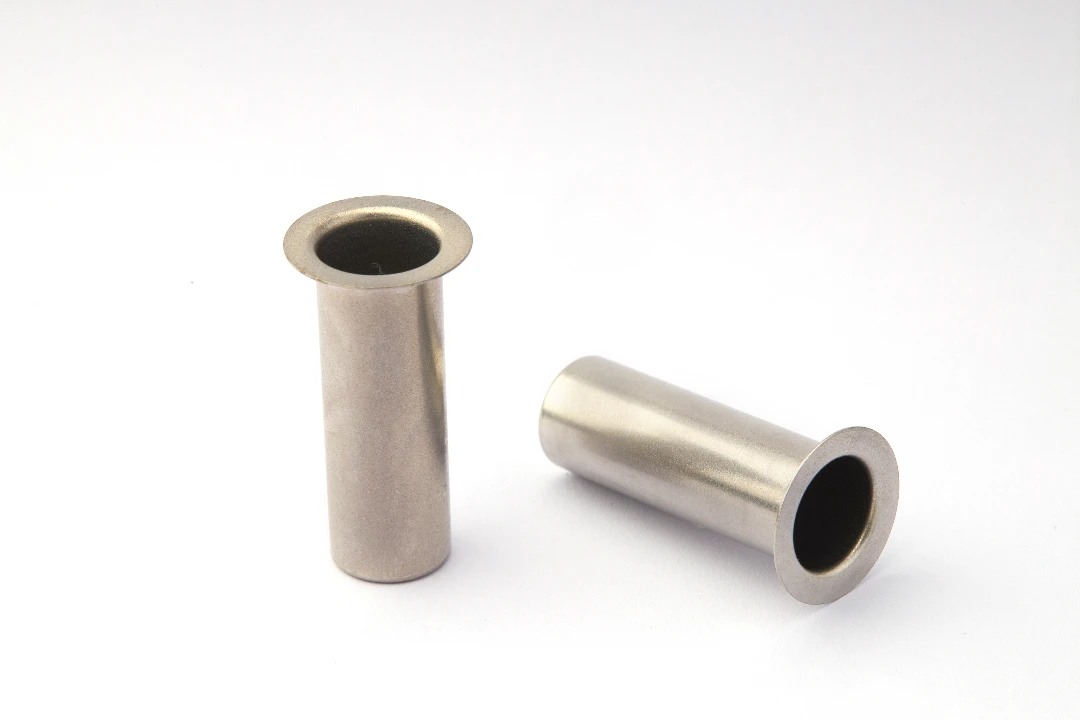
To design for the process, one must first respect the physics of the process. Deep drawn metal stamping is defined as a metal forming process in which sheet metal is stretched into a forming die by the mechanical action of a punch. It is considered “deep” drawing when the depth of the drawn part exceeds its diameter.
The Battle Between Tension and Compression
When the punch strikes the metal blank, the material is subjected to two opposing forces. The material at the bottom of the cup is under tension (stretching), while the material in the flange (the outer rim) is under circumferential compression as it is drawn inward toward the die cavity.
If the tension is too high, the bottom of the cup will tear off (fracture). If the compression is not controlled, the flange will wrinkle. A successful design balances these forces through geometry and material selection. According to standard metallurgical principles outlined by resources like MatWeb, understanding the ductility and work-hardening rate of your chosen alloy is the first step in predicting how it will react to these immense stresses.
Ironing vs. Drawing
It is also vital to distinguish between pure drawing and ironing. In pure drawing, the wall thickness remains roughly constant (though it naturally thickens at the top and thins at the bottom). Ironing is a secondary process where the wall thickness is intentionally reduced and uniformed. For JUMAI TECH clients requiring high-precision cylindrical components, knowing whether your part requires ironing is crucial, as it significantly impacts tooling costs and press tonnage requirements.
Material Selection: The Foundation of Success
Choosing the right material is arguably 50% of the battle in deep drawn metal stamping. You cannot simply specify “Aluminum” or “Steel”; you must specify the exact grade and temper. The material must possess the ductility to flow without fracturing, but the strength to maintain the finished shape.
Common Materials and Their Deep Drawing Characteristics
At JUMAI TECH, we specialize in processing a wide array of metals. Below is a comparison of common materials we handle, specifically regarding their suitability for deep drawing:
| Material Type | Common Grades | Drawability | Key Characteristics | Typical Applications |
| Copper Alloys | C11000 (ETP), C10200 (OFC) | Excellent | High electrical conductivity, highly ductile, works hardens slowly. | Precision Copper Busbars, Heat Sinks, Electrical Contacts. |
| Stainless Steel | 304, 304L, 316 | Good | High strength, excellent corrosion resistance. Work hardens very quickly (requires annealing). | Medical devices, sensor housings, food-grade containers. |
| Aluminum | 3003-O, 5052-O | Excellent to Good | Lightweight, soft. 3003 is very formable; 6061 is generally poor for deep drawing. | Automotive heat shields, battery enclosures, beverage cans. |
| Low Carbon Steel | 1008, 1010 | Excellent | Cost-effective, predictable grain structure. Needs plating for corrosion resistance. | Automotive structural parts, general enclosures. |
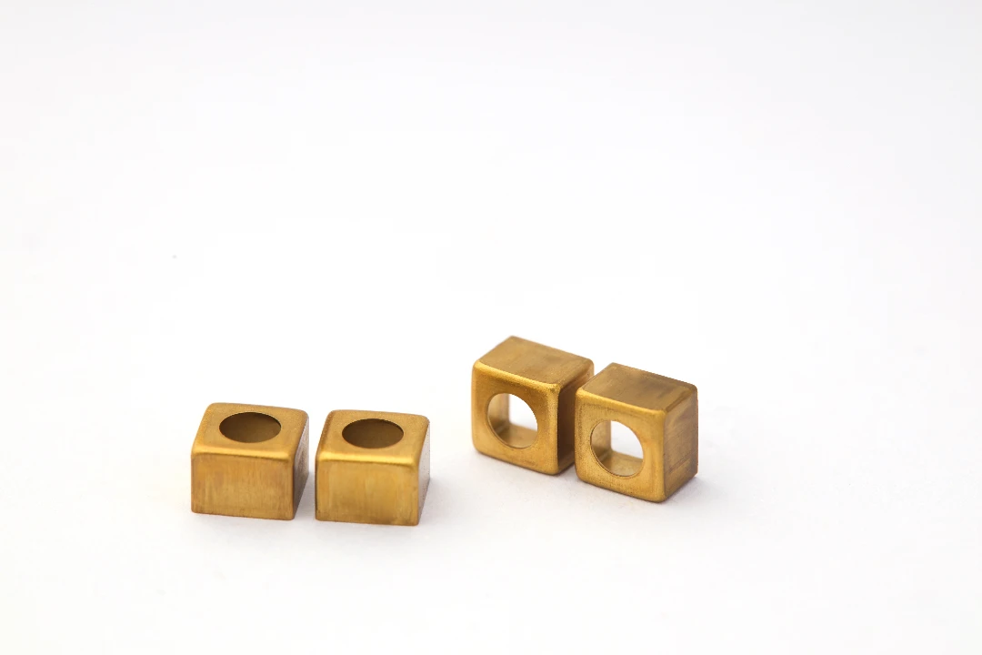
| Brass | 70/30 (Cartridge Brass) | Superior | The “gold standard” for drawability. Self-lubricating properties. | Ammunition casings, plumbing fittings, decorative hardware. |
The Importance of Grain Structure
For deep drawn parts, specifically Deep-Drawn Components like battery cans or sensor housings, the grain size of the metal matters. Large grains can improve ductility but often result in a surface defect known as “orange peel”—a rough, textured surface that appears after stretching.
Conversely, ultra-fine grains result in a smooth finish but may lack the elongation required for deep draws. When we consult with clients on Precision Stamping Dies, we often recommend specific material grain sizes to balance cosmetic requirements with formability.
Critical Design Rules for Geometry
When designing for deep drawn metal stamping, the geometry of the part dictates the complexity of the tooling. Simplification is the key to reliability.
Optimizing Corner Radii
The most common mistake we see in CAD files at JUMAI TECH is tight corner radii. In machining, a sharp corner is easy; in deep drawing, it is a stress concentrator.
- Punch Radius: The radius at the bottom of the cup (where the wall meets the floor). This should ideally be 4x to 8x the material thickness. If this radius is too small, the punch acts like a cutter, shearing the bottom of the cup out before the walls are formed.
- Die Radius: The radius at the opening of the die. This controls how easily the material flows into the cavity. A general rule of thumb is that the die entry radius should be roughly 6x to 10x the material thickness.
Draft Angles and Taper
While straight walls are possible, adding a slight taper (draft angle) to the vertical walls of your part can significantly improve manufacturability. Even a modest draft of 1° to 3° helps in:
- Reducing friction during the draw.
- Making it easier to eject the part from the die.
- Reducing wear on the Precision Stamping Dies.
Wall Thickness Consistency
In deep drawn metal stamping, you must generally design for uniform wall thickness. Unlike casting or molding, you cannot easily add “ribs” or variable thickness sections without expensive secondary operations. If your design requires a thick base and thin walls, we can achieve this through ironing, but it changes the cost structure. Always assume the material will thin by approximately 10-15% at the bottom radius and thicken by 15-20% at the top flange due to the mechanics of material flow.
Calculating the Limiting Draw Ratio (LDR)
One of the technical metrics we use daily at JUMAI TECH to determine feasibility is the Limiting Draw Ratio (LDR). The LDR determines if a part can be drawn in a single operation or if it requires multiple “reductions” (progressive drawing stations).
The Formula
The LDR is roughly defined as the ratio of the maximum blank diameter (D) to the punch diameter (d):
For most cylindrical steel parts, the maximum LDR for a single draw is approximately 2.0. This means if you have a punch diameter of 50mm, the starting blank cannot be larger than 100mm. If the part requires more material to reach the desired depth, it cannot be done in one hit.
Multi-Stage Reductions
If your design exceeds the LDR, we must use a multi-stage process. This involves:
- First Draw: Create a wide, shallow cup.
- Redraws: Step-by-step reduction of the diameter while increasing the length.
Each redrawing step adds to the cost of the Precision Stamping Dies. Therefore, designing a shallower, wider part is almost always cheaper than a tall, skinny part, provided it fits your application constraints. For detailed engineering data on draw ratios, resources like The SME (Society of Manufacturing Engineers) provide excellent technical papers.
Tolerancing: Precision vs. Practicality
Achieving “aerospace” tolerances on every dimension of a deep drawn part is a recipe for high costs and high scrap rates. It is vital to apply tight tolerances only where they govern fit and function.
Diameter vs. Length Tolerances
- Diameters: Because diameters are controlled by the hard tooling (the punch and die), they can be held very tightly (e.g., ±0.05mm or better, depending on size).
- Lengths (Depth): The overall height of a deep drawn part is much harder to control due to “earing” (waviness at the top edge caused by material anisotropy).
The Necessity of Trimming
Because of the uneven flow of material, the top edge of a deep drawn part will never be perfectly flat, straight out of the draw die. It will be wavy.
- Design Tip: Never dimension the top edge of a drawn part as a critical datum unless you are paying for a trimming operation.
- JUMAI TECH Standard: We almost always include a trimming station in our progressive dies to slice off the uneven edge and establish a precise height.
Managing Deep Drawn Defects
Even with perfect Precision Stamping Dies, defects can occur if the process parameters are not dialed in. Understanding these defects helps you design parts that are less prone to them.
1. Wrinkling
Wrinkling occurs in the flange when compressive forces buckle the material. This is common in thin materials or when the hold-down pressure is insufficient.
- Design Fix: Ensure the flange width is not excessive relative to the material thickness.
2. Tearing (Fracture)
This happens when the tensile stress in the wall exceeds the tensile strength of the material. It usually occurs near the punch radius.
- Design Fix: Increase the corner radius. Use a material with higher ductility. Improve lubrication.
3. Galling
Galling is the adhesion of the workpiece material to the die, causing scratches and tool damage. It is particularly common when drawing Stainless Steel or Aluminum.
- Design Fix: This is largely a manufacturing issue solved by advanced coatings (like TiCN or DLC) on our tooling, but selecting materials known for better tribology (like brass) can mitigate this risk in the design phase.
4. Springback
After the part is ejected from the die, the metal tries to return to its original shape. This affects the final diameter and the flatness of the bottom.
- Design Fix: At JUMAI TECH, we over-bend the material slightly in the tool design to account for this. However, designers should allow for looser tolerances on large, flat unsupported areas where springback is most unpredictable.
Cost Drivers in Deep Drawn Manufacturing
Our goal at JUMAI TECH is to provide the best value for Deep-Drawn Components and Precision Copper Busbars. Understanding what drives cost can help you value-engineer your product before sending us the RFQ.
Tooling Investment vs. Piece Price
Deep drawn metal stamping requires hard tooling. The initial investment for a progressive die or a transfer die can be significant ($5,000 to $50,000+, depending on complexity).
- Low Volume: For small runs (under 1,000 units), deep drawing may be too expensive due to tooling amortization. We might suggest metal spinning or machining.
- High Volume: For runs of 10,000 to millions, deep drawing is unbeatable. The per-piece cost drops dramatically because the process is fast (dozens of parts per minute) and generates less scrap than machining.
Material Utilization
Deep drawing uses a round blank cut from a square or rectangular strip. This inevitably leaves a “web” of scrap material.
- Optimization: We use nesting software to minimize scrap, but the geometry of your part dictates the blank size. Complex flanges or irregular shapes often result in higher scrap rates.
Secondary Operations
Does your part need holes, slots, or threads?
- In-Die Features: We can often pierce holes and form threads inside the stamping press using the progressive die. This is the cheapest method.
- Post-Machining: If holes are on the side walls or require extreme precision, we may need to CNC machine them after drawing, which increases costs.
JUMAI TECH: Your Partner in Precision
At www.deepdrawtech.com, we don’t just supply parts; we supply solutions. Our expertise extends beyond simple cups and cans.
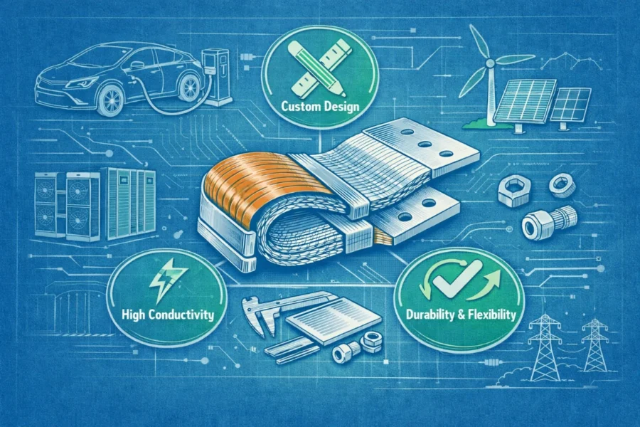
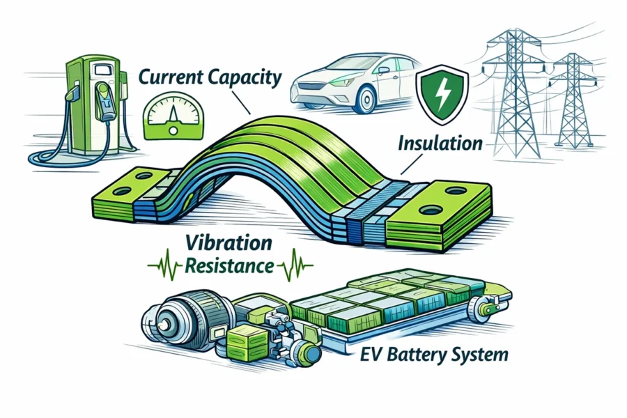
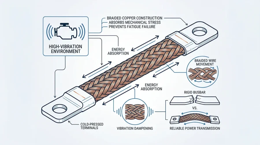
Focus on Precision Copper Busbars
One of our flagship capabilities is the production of Precision Copper Busbars. While often associated with bending and punching, complex busbar geometries for EV battery packs and power distribution often require deep drawing elements to create offset connection points or rigid structural features. Our experience with Copper C11000 allows us to achieve deep draws without compromising the electrical conductivity required for high-performance applications.
Engineering Support and Simulation
Before we cut a single piece of steel for the die, we utilize advanced Finite Element Analysis (FEA) software to simulate the deep drawn metal stamping process. This “virtual prototyping” allows us to:
- Predict thinning and thickening.
- Identify potential tearing points.
- Optimize the blank shape to reduce scrap.
This digital-first approach ensures that when we deliver your Precision Stamping Dies or finished parts, they work the first time, every time.
Conclusion
Designing for deep drawn metal stamping is a balance of creativity and constraint. By adhering to the principles of generous radii, appropriate material selection, and realistic tolerancing, you can harness the power of this manufacturing method to create robust, lightweight, and cost-effective components.
Whether you are developing a new line of automotive sensors, aerospace enclosures, or seeking a reliable partner for Precision Copper Busbars, JUMAI TECH is here to guide you through the process. We invite you to send us your 3D models and prints. Let our team of experts review your design for manufacturability and help you bring your vision to reality with the precision and quality that only JUMAI TECH can deliver.
Ready to start your next project? Contact our engineering team today at www.deepdrawtech.com for a comprehensive design review and quotation.
FAQ
What is deep drawn metal stamping?
Deep drawn metal stamping is a manufacturing process where a piece of flat metal is shaped into a hollow part by pulling it into a mold using a punch. This process allows for making strong and intricate parts, like automotive parts or electronics housings. It’s called ‘deep drawn’ when the depth of the part is greater than its diameter.
Why is material selection important in deep drawn metal stamping?
Choosing the right material is key to success in deep drawn metal stamping. The material must be strong enough not to break during the forming process, but also ductile enough to stretch and take the shape of the mold. For example, materials like certain aluminum and copper alloys are excellent for deep drawing because they can be bent without breaking.
What should I consider when designing parts for deep drawing?
When designing parts for deep drawing, consider the geometry, wall thickness, and radii. Sharp corners can create stress points that lead to failures. It is vital to use rounded corners and maintain uniform wall thickness throughout the part for better flow of material and to avoid defects.
What are common defects in deep drawn parts and how can I avoid them?
Common defects include wrinkling, tearing, and galling. To avoid wrinkling, ensure the flange width is appropriate; for tearing, increase corner radii or improve lubrication. Galling can be reduced by using materials that minimize wear on tools.
How do I calculate the Limiting Draw Ratio (LDR)?
The Limiting Draw Ratio is calculated by dividing the maximum diameter of the initial metal blank by the diameter of the punch used. An LDR of around 2.0 means if your punch has a diameter of 50mm, the starting metal blank should not be larger than 100mm.
What is the significance of corner radii in the design?
Corner radii are crucial in deep drawing as sharp corners can lead to fractures. Ideally, the radius at the bottom of the part should be 4 to 8 times the material thickness to ensure even material flow and reduce the risk of breaking.
What does tolerancing mean in deep drawn parts?
Tolerancing refers to the permissible limits of variation in a physical dimension. In deep drawn parts, tighter tolerances are essential for diameters, while lengths are harder to control due to material flow. It’s important to dimension only where precision is crucial.
How does the deep drawing process affect the cost of a project?
The cost of deep drawn parts can vary largely based on tooling, material, and design complexity. While initial tooling costs can be high, the per-piece pricing becomes lower with large production runs, making it economical for high-volume projects.
How can I ensure my design is manufacturable?
To ensure your design is manufacturable, consider consulting with a manufacturing expert early in the design process. They can help review your designs for potential issues and suggest necessary adjustments to improve manufacturability, reducing costs and lead times.