In the high-stakes world of electronic manufacturing, where signal integrity and environmental protection are paramount, the connector shell is the unsung hero. As the Editor-in-Chief at JUMAI TECH, and having spent years on the shop floor dealing with everything from customized Precision Copper Busbars to complex Deep-Drawn Components, I have seen firsthand how a fraction of a millimeter can mean the difference between a secure connection and a field failure.
We often talk about the conductivity of the pins or the insulation of the plastic, but the structural integrity of the metal housing—manufactured through deep drawn stamping—is what holds it all together. When clients come to us for Precision Stamping Dies, their first question is almost always about cost. But their second, and most critical question, is about tolerance.
This guide explores the technical landscape of achieving tight tolerances in deep drawn connector shells. We will dismantle the process, analyze the variables, and provide the data you need to make informed engineering decisions. Whether you are designing aerospace avionics or automotive sensor arrays, understanding the limits and capabilities of deep drawing is essential.
Table of Contents
Understanding the Physics of Deep Drawn Stamping
To control tolerances, one must first respect the physics of the process. Unlike simple bending or progressive stamping, where metal is primarily folded or sheared, deep drawn stamping involves a radical transformation of the metal’s crystalline structure. It is a process of tension and compression occurring simultaneously.
The Mechanics of Plastic Deformation
In deep drawing, a flat sheet of metal (the blank) is mechanically forced into a die cavity by a punch. The material is not just changing shape; it is flowing. The outer rim of the blank is subjected to compressive hoop stress as it moves toward the die radius, while the material along the cup wall undergoes tensile stress.
Successful deep drawing occurs in the plastic deformation range of the material, past the yield point but before the ultimate tensile strength, where fracturing occurs. For precision connector shells, which often have high length-to-diameter ratios, this flow must be perfectly controlled. If the metal flows too fast, it wrinkles; too slow, and it tears. Managing this flow is the secret to maintaining dimensional accuracy.
Why Deep Drawing is Superior for Connector Shells
You might ask, why not machine these shells? Or use die casting?
- Material Grain Structure: Deep drawing elongates the grain structure of the metal, actually work-hardening the part as it is formed. This results in a connector shell that is significantly stronger and more rigid than a machined part of the same thickness.
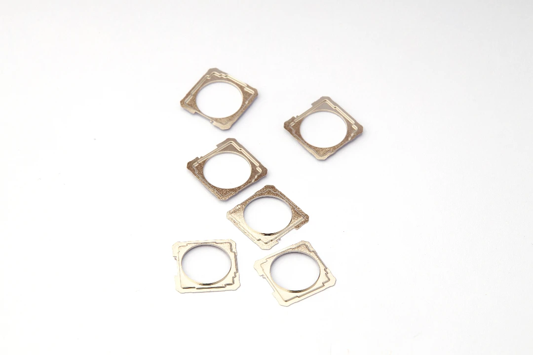
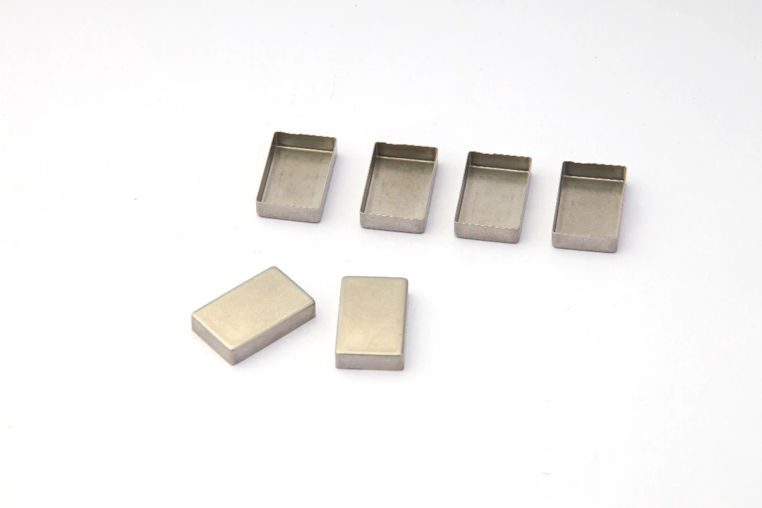
- Seamless Construction: Unlike folded sheet metal, deep drawn parts have no seams. This is non-negotiable for IP-rated waterproof connectors or applications requiring EMI/RFI shielding. A seamless cylinder offers zero leakage paths for radio frequency interference.
- Cost Efficiency at Scale: Once the Precision Stamping Dies are built, the unit cost drops dramatically compared to CNC turning.
The Critical Importance of Tolerances in Connector Shells
In my experience processing Deep-Drawn Components for global OEMs, “tolerance” is not just a number on a print; it is a functionality requirement. For connector shells, tolerance deviations manifest in three critical failure modes.
Signal Integrity and EMI Shielding
Modern electronics operate at high frequencies. The connector shell often acts as a Faraday cage, grounding out interference. If the tolerance on the inner diameter (ID) is too loose, the fit with the mating connector or the internal shielding components will be sloppy. This gap creates an aperture where electromagnetic noise can leak in or out.
For effective shielding, the fit must be consistent around the entire circumference. We often see requirements for concentricity tolerances within ±0.03mm to ensure that the shielding effectiveness (SE) remains high across the full frequency spectrum.
Mating Force and Retention
The “click” of a connector is a feature of precise engineering. The force required to mate and unmate a connector is heavily influenced by the frictional interference between the shell and the receptacle.
- Too Tight: The connector jams, potentially bending pins or damaging the PCB during installation.
- Too Loose: The connector creates an intermittent circuit under vibration (a nightmare in automotive applications).
Waterproofing and Environmental Sealing
Many JUMAI TECH clients request shells for IP67 or IP68 rated connectors. These rely on O-rings or potting compounds. If the deep drawn shell has significant “earing” (waviness at the top edge) or ovality, the O-ring will not compress evenly. A deviation of just 0.05mm in the sealing zone can lead to water ingress, corrosion, and total system failure.
Key Variables Influencing Deep Drawn Stamping Tolerances
Achieving precision isn’t magic; it’s the management of variables. In the production of Precision Stamping Dies, we constantly battle several physical factors that fight against tight tolerances.
Material Anisotropy and Earing
Metal is not perfectly isotropic; its properties vary depending on the direction of the grain (which was created when the metal coil was rolled at the mill). When we draw a cylindrical connector shell, the metal flows differently “with the grain” versus “across the grain.”
This results in a defect known as earing—a wavy edge at the top of the drawn part.
- The Tolerance Impact: Earing makes it difficult to hold a tight total height tolerance without a secondary trimming operation.
- ** The Solution:** At JUMAI TECH, we source raw materials with controlled grain structures and utilize “pinch trimming” operations within the die to shear off the ears, ensuring a perfectly flat sealing edge.
Springback
All metals have elasticity. After the punch retracts, the metal tries to return to its original shape. This is called springback. In deep drawn stamping, this usually manifests as the diameter of the shell expanding slightly after ejection from the die.
- High-Yield Strength Materials: Stainless steel (often used for rugged connectors) has higher springback than copper or brass.
- Compensation: We design our Precision Stamping Dies to over-bend slightly, allowing the part to spring back into the correct tolerance. This requires sophisticated simulation software and experienced toolmakers to predict.
Die Wear and Thermal Expansion
In high-volume production (millions of strokes), friction generates heat and wears down the tooling.
- Thermal Expansion: As the die heats up, the cavity gets smaller (metal expands inward) and the punch gets bigger. This changes the clearance and the resulting wall thickness of the part.
- Tool Wear: As the draw ring wears, the friction coefficient changes, altering how the material flows. This can lead to wall thinning or tearing.
Achievable Tolerances: Standard vs. Precision
One of the most common questions I receive via our website is: “What tolerances can you actually hold?” The answer depends on the material, the geometry, and the budget for tooling.
Below is a reference table based on standard DIN norms versus what we achieve at JUMAI TECH through high-precision tooling and process control.
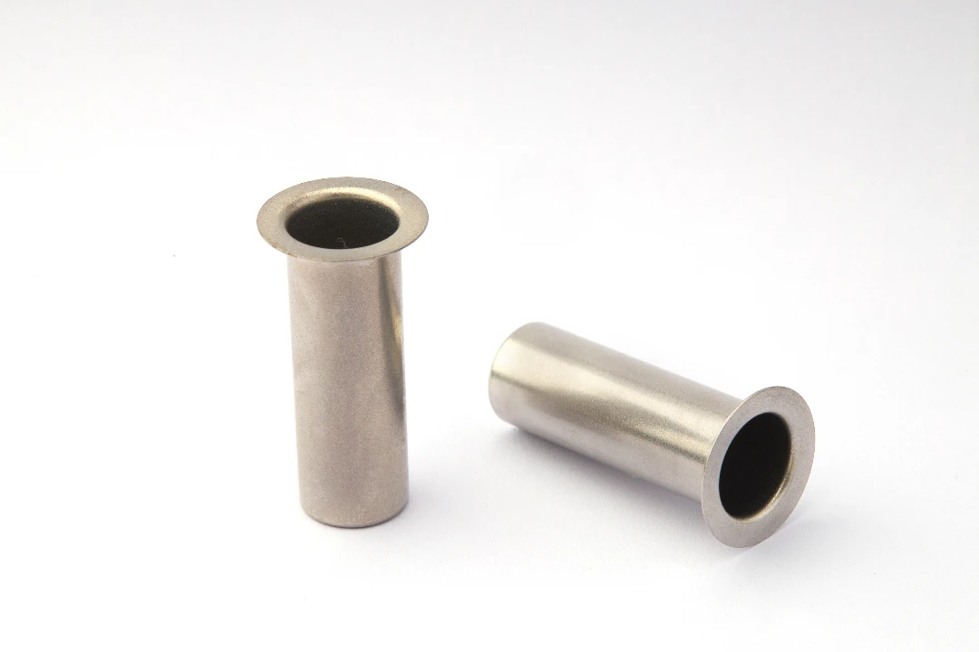
Comparative Tolerance Table for Deep Drawn Cylindrical Shells
| Feature Dimension | Standard Tolerance (ISO 2768-m) | High Precision Tolerance (JUMAI Capability) | Notes |
| Diameter (Ø < 10mm) | ± 0.10 mm | ± 0.02 mm | Achieved via ironing steps. |
| Diameter (Ø 10-30mm) | ± 0.20 mm | ± 0.04 mm | Critical for mating interface. |
| Total Length (Height) | ± 0.20 mm | ± 0.05 mm | Requires pinch trim operation. |
| Wall Thickness | ± 10% of stock | ± 0.015 mm | Controlled via clearance gaps. |
| Concentricity | 0.10 mm TIR | 0.03 mm TIR | Vital for coaxial connectors. |
| Corner Radius | ± 0.50 mm | ± 0.10 mm | Depends on material ductility. |
Note on Data: These figures represent typical capabilities for Brass (C26000) and Stainless Steel (304/316). Softer materials like Aluminum may require different parameters. For authoritative data on general metal tolerances, reputable sources likeISO.orgprovide the baseline standards which specialized manufacturers strive to exceed.
The Role of “Ironing” in Precision
To achieve the high-precision values listed above, we often employ a process called ironing. In a standard deep draw, the wall thickness naturally thickens near the top of the shell and thins near the bottom.
In an ironing operation, the clearance between the punch and the die is set to be less than the material thickness. This forces the wall to thin out and elongate, effectively “squeezing” the metal to a uniform thickness. Ironing is the gold standard for achieving high concentricity and uniform wall thickness in connector shells.
Material Selection: Balancing Formability and Function
The choice of material dictates the achievable tolerance as much as the tooling does. In my years working with Precision Copper Busbars, I learned that copper behaves very differently from the stainless steel used in rugged shells.
Stainless Steel (304/316 Series)
- Pros: Excellent corrosion resistance, high strength, superior shielding for low frequencies.
- Cons: Work hardens rapidly. Requires higher press forces and high-performance lubricants. High springback makes diameter tolerances harder to hold without ironing.
- Application: Military, Aerospace, and Marine connectors.
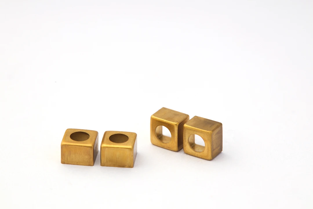
Brass (C26000 / Cartridge Brass)
- Pros: The “king” of deep drawing. Excellent ductility, low tool wear, easily plated (Nickel, Gold, Tin).
- Cons: Lower strength than steel. Can be susceptible to stress corrosion cracking if not properly annealed.
- Application: Commercial electronics, USB shells, audio jacks.
Copper (C11000)
- Pros: Incredible thermal and electrical conductivity. Very malleable.
- Cons: Very soft; can be easily deformed during handling (bulk packaging). Requires careful packaging design.
- Application: Power connectors, battery terminals.
We often consult the Copper Development Association guidelines when advising clients on specific alloy choices to ensure the material properties align with the deep drawing process requirements.
Advanced Tooling Strategies for Tight Tolerances
At JUMAI TECH, we don’t just run parts; we engineer the Precision Stamping Dies that make them. The difference between a loose part and a precision part lies inside the tool.
Progressive vs. Transfer Dies
For deep drawn connector shells, the choice of die type impacts tolerance accumulation.
- Progressive Dies: The part stays attached to the metal strip as it moves through stations.
- Advantage: High speed (up to 100+ strokes per minute).
- Tolerance Risk: The flexibility of the carrying strip can introduce slight misalignment between stations, affecting concentricity.
- Transfer Dies: The part is cut loose and mechanically transferred between stations by fingers or robotic arms.
- Advantage: The part can be allowed to rotate or float, which often results in better roundness and concentricity. It allows for processing the entire circumference without a carrier strip tab interference.
Carbide Tooling
For high-volume, high-precision runs, we utilize Tungsten Carbide inserts for punches and dies. Carbide is significantly harder and more wear-resistant than tool steel.
- Benefit: It maintains dimensional stability over millions of cycles. A steel die might open up by 0.01mm after 100,000 hits, but a carbide die will hold that dimension for millions of hits, ensuring the first part and the millionth part are identical.
In-Die Sensing and Adjustment
Modern deep drawn stamping isn’t blind. We employ in-die sensors that monitor:
- Double Sheet Detection: Prevents two sheets from entering, which would destroy the precision tooling.
- Ejection Monitoring: Ensures the part has left the die before the next stroke.
- Force Monitoring: Detecting slight variations in forming force can indicate material thickness changes or tool wear before the parts go out of spec.
Quality Control and Metrology
You cannot manufacture precision if you cannot measure it. In the domain of Deep-Drawn Components, traditional calipers are often insufficient because they can deform thin-walled shells during measurement.
Non-Contact Optical Measurement
We utilize automated optical inspection systems (Vision Systems). These place the connector shell on a glass stage and use high-resolution cameras and backlighting to measure the profile.
- Advantage: Instantly measures diameter, length, and radii without touching the part.
- Speed: Can measure hundreds of features in seconds.
Coordinate Measuring Machines (CMM)
For complex geometries or checking the position of stamped features relative to the drawn shell (like a locking tab), we use CMMs. While slower, they provide the 3D data needed to verify GD&T (Geometric Dimensioning and Tolerancing) callouts like perpendicularity and true position.
Statistical Process Control (SPC)
We don’t just check the final parts; we monitor the trend. By taking samples every hour and plotting the dimensions on control charts (X-bar and R charts), we can see if a dimension is “drifting” toward the tolerance limit.
- Proactive Maintenance: If we see the Outside Diameter (OD) trending upward, we know the die is wearing or the lubrication is changing, and we can stop the press before we make bad parts.
JUMAI TECH: Your Partner in Precision
The deep drawing process is a blend of metallurgical science and engineering art. When you are designing a precision connector shell, you need a partner who understands more than just “punch and die.” You need a partner who understands Precision Copper Busbars, the intricacies of Precision Stamping Dies, and the global standards of electronic components.
At DeepDrawTech.com (JUMAI TECH), we bring years of specialized experience to the table. We don’t just sell parts; we sell process stability. Whether you need a prototype run of 500 pieces or mass production of 50 million units, our approach to tolerance control remains uncompromising.
Our Commitment to You
- DFM Support: We review your drawings before tooling begins to suggest tolerance adjustments that save money without sacrificing performance.
- Tooling Ownership: We design and maintain our dies in-house, ensuring that wear-and-tear never impacts your supply chain.
- Global Logistics: We understand the supply chain demands of global clients, offering JIT (Just-In-Time) delivery options.
Ready to elevate your connector manufacturing?
Don’t let tolerance issues compromise your product’s reputation. Contact the engineering team at JUMAI TECH today. Let us review your designs and show you how deep drawn stamping can provide the precision, strength, and scalability your project deserves.
FAQ
What is deep drawn stamping?
Deep drawn stamping is a manufacturing process where a flat sheet of metal is reshaped into a three-dimensional part. This process involves forcing the metal into a mold called a die. By doing this, the metal becomes stronger and takes on a new shape without seams, making it ideal for creating robust connector shells used in electronics.
Why are tolerances important in connector shells?
Tolerances are crucial in connector shells because they determine how well various parts fit together. If the dimensions are off, it can lead to problems. For example, a connector that is too loose may cause electrical interference or fail to connect properly, while one that is too tight might get stuck or damage other components during installation.
What factors affect the tolerances in deep drawn parts?
Several factors can impact tolerances in deep drawn parts, including the type of material used and the design of the die. Material properties like strength and elasticity can influence how much the metal changes shape. Additionally, the technical precision of the tooling and how well the manufacturing process is controlled are also key factors.
What are acceptable tolerance levels for deep drawn connector shells?
Acceptable tolerance levels can vary based on the specific requirements of the connector shell. Generally, standard tolerances can be around ±0.2 mm for diameter and length, while high precision parts can achieve tolerances as tight as ±0.03 mm, especially for critical applications. This means it’s important to communicate specific needs when designing the connectors.
What materials are commonly used for deep drawn connector shells?
Common materials for deep drawn connector shells include stainless steel, brass, and copper. Stainless steel is strong and resists corrosion but can be tricky to form. Brass offers excellent flexibility and is easier to work with, while copper is great for electrical conductivity but must be handled with care due to its softness.
How does deep drawn stamping compare to other manufacturing methods?
Deep drawn stamping is often preferred over methods like machining or die casting because it results in stronger components without seams. Additionally, it is more cost-effective for mass production since, after the initial setup, producing each part costs less, leading to lower prices for larger quantities.
What is the process of inspecting deep drawn components?
Inspecting deep drawn components typically involves both contact and non-contact methods. Non-contact optical measurement systems use cameras to measure dimensions quickly, while Coordinate Measuring Machines (CMM) provide detailed 3D profiles of the parts, ensuring all features meet the design specifications.
Can deep drawn stamping support high volume production?
Yes, deep drawn stamping is highly suitable for high-volume production. Once the dies are designed and built, they can produce thousands or even millions of parts at a very fast pace, maintaining high precision and low production costs, which is ideal for large-scale manufacturing needs.
How does JUMAI TECH ensure precision in deep drawn stamping?
At JUMAI TECH, we use advanced tooling strategies, high-quality materials, and strict quality control processes to ensure precision in deep drawn stamping. Our engineers constantly monitor production and make adjustments as needed to maintain tight tolerances, so clients can trust the quality and consistency of their parts.
How can I get started with JUMAI TECH for my project?
Getting started with JUMAI TECH is simple! You can reach out to our engineering team via our website. We offer design reviews to optimize your drawings, ensuring the best balance between performance and cost. Whether you need a few prototypes or mass production, we’re here to help you meet your project goals.