In the rapidly evolving landscape of power distribution, the efficiency of energy transfer is not just a detail—it is the backbone of modern innovation. Whether we are discussing the intricate battery packs of Electric Vehicles (EVs), the high-density server racks in hyperscale data centers, or industrial switchgear, the method used to conduct high-current electricity defines the system’s reliability. This is where the Rigid Busbar steps in as the undisputed champion of high-power engineering.
At JUMAI TECH (www.deepdrawtech.com), We have spent years perfecting the art of metal fabrication. From our roots in Precision Stamping Dies to our advanced capabilities in Deep-Drawn Components and Precision Copper Busbars, we understand that a busbar is more than just a piece of metal. It is a critical thermal and electrical component that must be engineered with precision.
This guide serves as a definitive resource for engineers, procurement managers, and designers. We will dismantle the complexities of rigid busbar design, explore the metallurgy of materials, analyze surface treatments, and demonstrate why rigid busbars remain the superior choice for high-power applications.
Table of Contents
What is a Rigid Busbar?

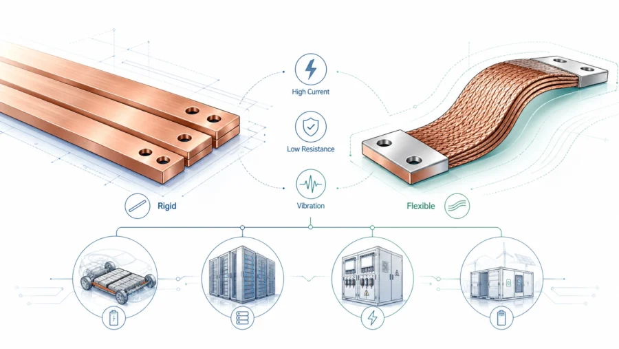
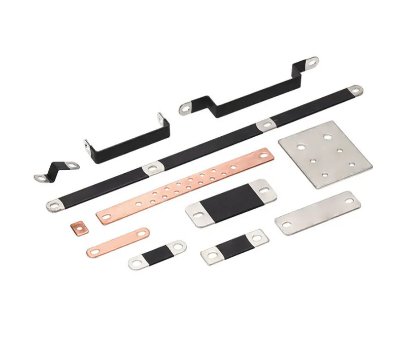
A Rigid Busbar is a solid, flat conductor—typically manufactured from copper or aluminum—used to distribute high-current power within an electrical system. Unlike cables, which are composed of stranded wires and insulation, rigid busbars are structural elements. They do not just carry current; they provide mechanical stability, reduce inductance, and offer superior thermal management characteristics.
In the world of power electronics, “rigid” implies that the conductor holds its shape under its own weight and withstands the mechanical forces generated during short-circuit events. While flexible busbars (stacked copper foils) have their place in vibration-heavy environments, rigid busbars are the industry standard for main power distribution backbones where efficiency and space optimization are paramount.
The Shift from Cable to Busbar
Why are industries transitioning away from heavy cabling? The answer lies in physics and geometry. Round cables suffer from inefficient packing densities; when you bundle round cables, you lose significant space between them. A flat rigid busbar, however, allows for compact, low-profile designs. Furthermore, the flat surface area of a rigid busbar is far more efficient at dissipating heat via convection and radiation compared to a round cable with thick insulation.
For JUMAI TECH, producing a rigid busbar is not merely about cutting metal. It involves complex precision stamping, bending, and sometimes deep drawing connection points to ensure the path of least resistance—both electrically and mechanically.
Material Selection: The Foundation of Conductivity
The performance of any rigid busbar begins with metallurgy. Choosing the right material is a balancing act between electrical conductivity, mechanical strength, weight, and cost. While exotic alloys exist, the market is dominated by two primary metals: Copper and Aluminum.
1. Copper: The Gold Standard (Almost)
Copper is the default choice for high-performance rigid busbars. Its atomic structure allows electrons to move with minimal resistance, making it second only to silver in terms of conductivity among practical metals.
Electrolytic Tough Pitch (ETP) Copper (C11000)
For 90% of standard applications, C11000 is the go-to grade. It boasts a conductivity rating of 101% IACS (International Annealed Copper Standard). It provides excellent thermal conductivity and is relatively easy to stamp and bend. However, it contains trace amounts of oxygen, which can cause hydrogen embrittlement if welded in a reducing atmosphere.
Oxygen-Free High Conductivity (OFHC) Copper (C10100/C10200)
When the application requires extensive welding, brazing, or deep drawing without the risk of embrittlement, we utilize Oxygen-Free copper. At JUMAI TECH, we often recommend this for medical devices or vacuum applications where material purity is non-negotiable.
2. Aluminum: The Lightweight Contender
Aluminum is approximately 62% as conductive as copper but is 70% lighter. This makes it an attractive option for industries where weight is a penalty, such as aerospace or mass-transportation systems.
However, substituting aluminum for copper is not a 1:1 swap. To carry the same amount of current, an aluminum busbar must have a cross-sectional area approximately 1.6 times larger than a copper equivalent. This increase in volume can be a dealbreaker in compact electronic enclosures. Furthermore, aluminum forms a hard, resistive oxide layer almost instantly upon exposure to air, necessitating aggressive surface treatments and platings to ensure reliable electrical contact.
Comparative Data: Copper vs. Aluminum
To help you visualize the trade-offs, refer to the comparison table below regarding standard busbar materials:
| Property | Copper (C11000) | Aluminum (6061-T6) |
| Conductivity (% IACS) | 101% | 40-43% |
| Electrical Resistivity (Ω·mm²/m) | 0.0172 | 0.0400 |
| Density (g/cm³) | 8.94 | 2.70 |
| Melting Point (°C) | 1083 | 660 |
| Modulus of Elasticity (GPa) | 117 | 69 |
| Thermal Conductivity (W/m·K) | 391 | 167 |
| Approximate Cost Ratio | High (Base) | Low (~0.3x of Copper) |
Data Source: Adapted from standard material property sheets and Copper Development Association data.
Engineering Design Principles for Rigid Busbars
Designing a rigid busbar requires a deep understanding of electrical physics. At JUMAI TECH, when we assist clients with Precision Stamping Dies for busbar production, we review their designs against several critical engineering criteria.
Ampacity and Temperature Rise
Ampacity is the maximum current a conductor can carry continuously without exceeding its temperature rating. Unlike a wire gauge chart, busbar ampacity is not a fixed number; it is a function of the allowable temperature rise.
The standard formula used to estimate temperature rise is based on the surface area available for cooling. A common industry standard (DIN 43671) suggests that for a temperature rise of 30°C, a current density of approximately 2A/mm² is acceptable for bare copper. However, this is a simplification.
Engineers must calculate ampacity based on:
- Ambient Temperature: A busbar in a 25°C room behaves differently than one inside an 80°C engine bay.
- Ventilation: Is the air stagnant (natural convection) or moving (forced convection)?
- Emissivity: A painted or insulated busbar actually dissipates heat better than a shiny, bare metal busbar because the emissivity factor is higher, aiding radiative cooling.
The Skin Effect
For Direct Current (DC) applications, current flows uniformly through the entire cross-section of the busbar. However, in Alternating Current (AC) applications, the physics changes. Due to self-inductance, the current tends to crowd toward the outer surface of the conductor. This is known as the Skin Effect.
As the frequency increases, the effective cross-sectional area decreases, increasing the resistance.
- Design Tip: For high-frequency AC applications, a thin, wide rigid busbar is far superior to a thick, narrow one. The rectangular shape maximizes surface area, mitigating the skin effect and improving cooling.
Short Circuit Mechanical Forces
One of the most overlooked aspects of rigid busbar design is mechanical strength. During a short circuit fault, massive currents flow through the bars, generating intense magnetic fields. If two busbars run parallel to each other, these magnetic fields create a physical force (Lorentz force) that either attracts or repels the bars.
These forces can be instantaneous and destructive, capable of bending copper bars or shattering the insulators holding them. JUMAI TECH engineers use simulation software to calculate these potential forces, ensuring that the mounting brackets and the busbar thickness are sufficient to withstand fault conditions without catastrophic failure.
Clearance and Creepage Distances
Safety is paramount. Electrical arcing can occur if conductors are too close.
- Clearance: The shortest distance through the air between two conductive parts.
- Creepage: The shortest distance along the surface of a solid insulating material between two conductive parts.
Standards such as UL 840 and IEC 60664 dictate these minimum distances based on the voltage level and the pollution degree of the environment (e.g., a clean server room vs. a dusty factory). When space is tight, we often employ custom deep-drawn insulation barriers or specific bending geometries to artificially increase the creepage distance without expanding the footprint.
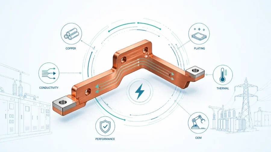
Surface Treatments and Plating Technologies
Raw copper is an excellent conductor, but it is chemically reactive. Over time, copper oxidizes, forming a layer of copper oxide. While copper oxide is not an insulator, it is a semiconductor with higher resistance than the base metal. This increased resistance leads to heat at the joints, which accelerates oxidation—a vicious cycle that leads to failure.
To prevent this, plating is essential. At JUMAI TECH, we offer several plating finishes depending on the application lifecycle and budget.
1. Tin Plating (The Industry Standard)
Tin is the most common plating for rigid busbars. It is cost-effective and provides good corrosion resistance.
- Pros: Excellent for preventing oxidation; soft metal ensures good contact surface conformity.
- Cons: Subject to “fretting corrosion” in high-vibration environments; lower melting point restricts extremely high-temp applications.
- Application: General industrial switchgear, renewable energy inverters.
2. Silver Plating (High Performance)
Silver is the best electrical conductor known to man. Silver oxide is also conductive (unlike copper oxide), which means even if the surface tarnishes, the electrical connection remains stable.
- Pros: Lowest contact resistance; excellent for high-temperature applications; superior longevity.
- Cons: Expensive; sensitive to sulfur in the atmosphere (tarnishing).
- Application: High-voltage substations, aerospace, high-performance EVs.
3. Nickel Plating (Harsh Environments)
Nickel is harder than tin or silver and highly resistant to corrosion.
- Pros: Withstands high temperatures and aggressive chemical environments.
- Cons: Higher contact resistance than tin or silver; requires a higher clamping force to break through surface oxides for a good connection.
- Application: Marine environments, chemical processing plants.
Manufacturing Process: Precision Meets Power
The fabrication of a rigid busbar at JUMAI TECH is a testament to the integration of Precision Stamping Dies and CNC technology. It is not a simple cutting operation; it is a multi-step process designed to maintain the integrity of the grain structure of the metal.
1. Punching and Stamping
For high-volume production, we utilize progressive stamping dies. These dies are engineered in-house to punch holes, slots, and intricate shapes with micron-level precision. The quality of the “cut edge” is vital. Poor stamping can lead to burrs.
- The JUMAI Difference: We ensure the “burr height” is kept to an absolute minimum (typically <10% of material thickness). Burrs can cut through insulation or prevent flush mating surfaces, leading to hot spots.
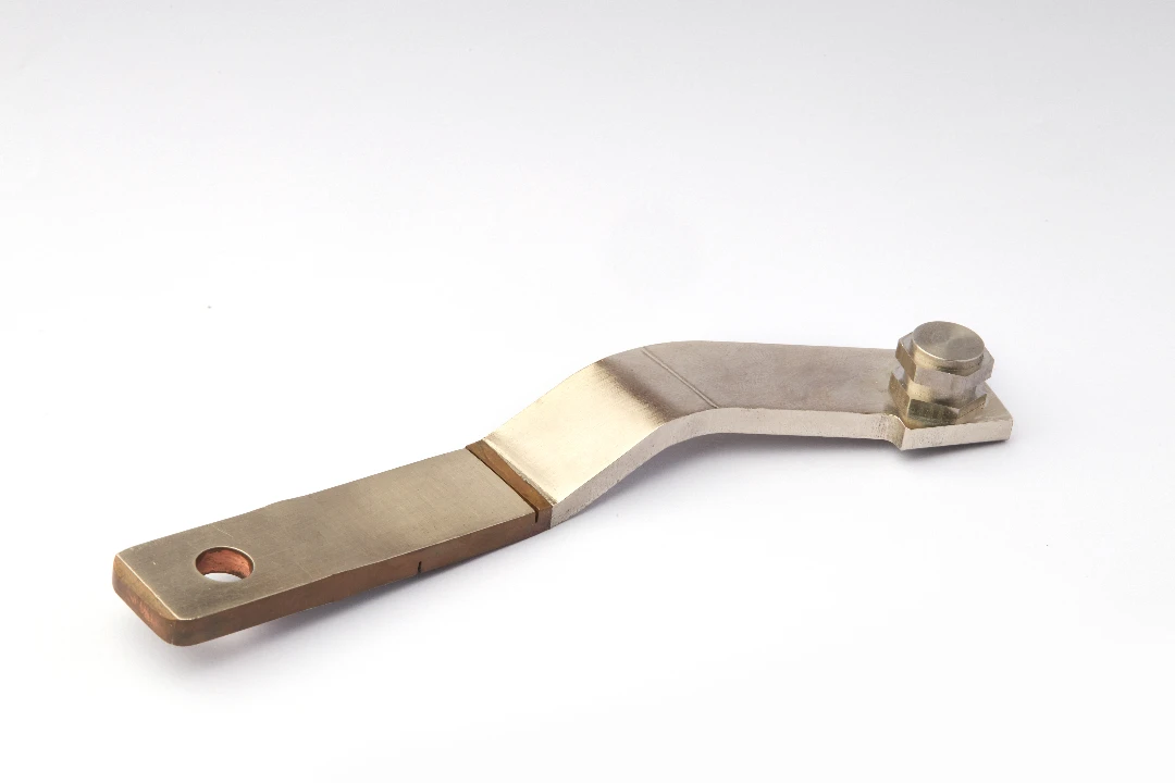
2. Bending and Forming
Bending a rigid busbar is more complex than it appears due to a phenomenon called Springback. When you bend copper, it has a natural tendency to return slightly to its original shape.
Our press brakes and bending robots are programmed with material-specific algorithms that over-bend the metal by a calculated degree so that it springs back to the exact required angle.
- Minimum Bend Radius: To prevent micro-cracks on the outer radius of a bend, we adhere to strict bend radius guidelines (typically 1x to 2x the material thickness, depending on the alloy temper).
3. Deep Drawing and Features
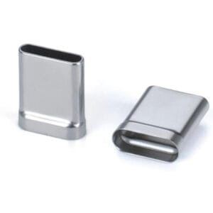
As experts in Deep-Drawn Components, JUMAI TECH can integrate unique 3D features into busbars. For example, we can deep-draw a “cup” or embossment around a mounting hole. This allows a screw head to sit flush with the surface (countersinking without removing material) or provides a rigid spacer integrated directly into the busbar, eliminating the need for loose washers.
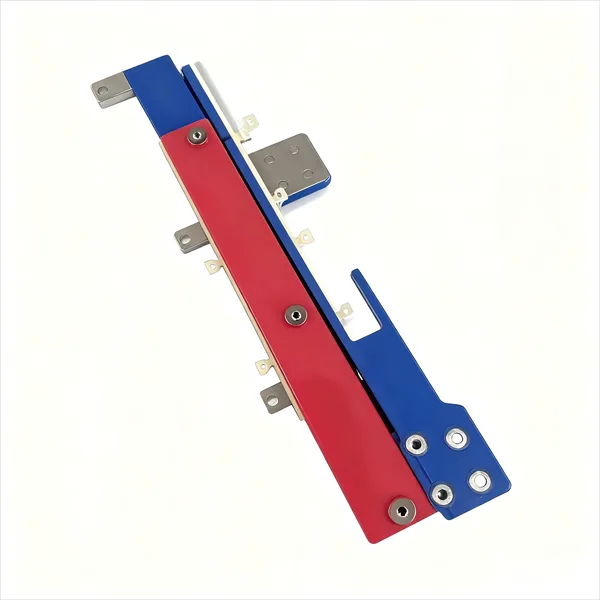
4. Insulation Application
Once the mechanical fabrication is complete, the busbar is often insulated to protect against accidental contact and short circuits.
- Heat Shrink Tubing: The most common method. A polyolefin tube is slipped over the bar and shrunk using heat. It is cost-effective but struggles with complex geometries.
- Epoxy Powder Coating (Fluidized Bed): The busbar is heated and dipped into a bed of epoxy powder. The powder melts and cures, forming a continuous, hard shell. This is ideal for complex shapes and offers high dielectric strength (typically 1000V+ per mil).
Key Applications Driving Demand
The demand for rigid busbars is skyrocketing, driven by global trends in electrification and data processing.
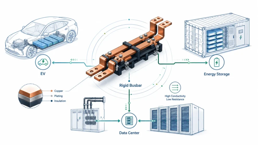
Electric Vehicles (EV) and Battery Packs
In an EV battery pack, space is money. Manufacturers cannot afford the bulk of heavy cables connecting hundreds of battery cells. Rigid busbars serve as the main interconnects, linking modules in series or parallel.
- Requirement: These busbars must handle hundreds of Amperes during fast charging and discharge, withstand the vibration of the road, and be incredibly lightweight. Custom-stamped aluminum busbars are frequently used here to save weight.
Renewable Energy Systems
Solar inverters and wind turbine converters manage massive power loads. A solar farm inverter might process Megawatts of power. Rigid busbars are used to link the DC input from the panels and the AC output to the grid.
- Challenge: These systems operate outdoors for 20+ years. The busbars must be plated and insulated to withstand thermal cycling and humidity without degrading.
Data Centers and Power Distribution Units (PDUs)
Modern AI processors and servers consume immense power. Traditional power strips are obsolete. Overhead busway systems and rack-mounted rigid busbars deliver power directly to the servers.
- Trend: “Smart Busbars” that integrate current-sensing technology are becoming common, allowing facility managers to monitor power usage in real-time.
Why JUMAI TECH is Your Ideal Partner
At JUMAI TECH, we bridge the gap between design and manufacturing. Our background in Precision Copper Busbars and Precision Stamping Dies means we don’t just follow a drawing—we optimize it.
- DFM (Design for Manufacturing) Support: We review your rigid busbar designs to suggest changes that reduce waste, lower tooling costs, and improve electrical performance.
- Integrated Capabilities: We handle everything from the raw copper sheet to the final plated and insulated component. We also manufacture the Deep-Drawn Components and accessories that often accompany busbar assemblies, providing a one-stop solution.
- Global Standards: We are familiar with manufacturing to UL, IEC, and ISO standards, ensuring your products are ready for the global market.
If you are designing a new power distribution system, do not underestimate the complexity of the busbar. It is the artery of your system.
Ready to optimize your power distribution? Contact the engineering team at JUMAI TECH today. Let us apply our decades of expertise in rigid busbar design and precision manufacturing to power your next innovation. Visit us at www.deepdrawtech.com to request a quote or consultation.
FAQs for Rigid Busbar Design
Why are rigid busbars preferred over traditional cables in compact cabinet designs?
Rigid busbars offer a much smaller bending radius (can be bent at 90-degree angles) and a higher surface-area-to-volume ratio. This allows for more compact routing and better heat dissipation, enabling engineers to reduce the overall footprint of electrical enclosures.
How does the orientation of a rigid busbar affect its thermal performance?
Orientation significantly impacts convective cooling. Positioning a busbar vertically (on its edge) is most efficient, as it creates a “chimney effect” that accelerates airflow. Horizontal placement is less efficient because heated air can become trapped under the bar, reducing cooling efficiency by up to 25%.
What measures should be taken to manage thermal expansion in rigid busbar systems?
Since rigid busbars do not naturally absorb expansion like cables, designers integrate “expansion offsets” or “omega (Ω) bends.” These pre-formed geometries allow the metal to expand and contract longitudinally without putting excessive mechanical stress on insulators or terminals.
What are the advantages of using epoxy powder coating for busbar insulation?
Epoxy coating provides a “conformal” fit that adheres tightly to the busbar’s geometry, including sharp bends. Unlike heat shrink tubing, which may thin out at corners, epoxy maintains consistent dielectric strength and offers superior thermal conductivity, aiding in heat dissipation.
How do rigid busbars improve the reliability of electrical connections over time?
Rigid busbars use bolted joints with high-tensile steel bolts and Belleville washers. This setup maintains constant pressure during thermal cycling, preventing the “cold flow” and loosening often seen in crimped cable lugs. This results in stable, low-resistance connections that last for decades.