Electric vehicles are rewriting the rules for power distribution inside a compact, vibration-prone, heat-limited space: the battery pack. In that environment, a copper busbar is not “just a conductor”—it’s a structural, thermal, and reliability-critical component that affects efficiency, safety, manufacturability, and service life.
Global EV adoption is also moving from “early adopter” to “mass market,” which raises the bar for repeatable quality, traceability, and scalable production. The International Energy Agency reports EV sales reached nearly 14 million in 2023 (about 18% of all car sales), reinforcing why battery-pack electrical architecture is now a mainstream engineering priority.
Why the EV Era Is a Busbar Era

High current, low loss—every milliohm matters
Battery packs and traction systems routinely carry large currents, especially during acceleration and fast charging. That makes resistive losses (I²R heating) a design constraint, not a rounding error, because wasted heat must be removed from an already crowded pack. A well-designed copper busbar helps reduce resistive drop and keeps temperature rise under control, which supports stable performance across driving cycles.
Copper is widely used in busbar applications because it combines high electrical conductivity with strong mechanical performance in compact cross-sections. Industry references describing busbar systems emphasize copper’s suitability for low-resistance power distribution and robust jointing in demanding installations. Copper Development Association
Space and weight trade-offs inside battery packs
In EV battery packs, packaging efficiency is a hidden cost driver. If a conductor requires a larger cross-section to carry the same current, it steals volume from cells, cooling channels, sensors, and safety features. Copper’s higher conductivity allows designers to achieve target resistance with less conductor volume than lower-conductivity alternatives, which can simplify routing and improve pack density.
At the same time, weight is not optional. The best solution is rarely “maximum copper everywhere,” but rather right-sized copper busbars placed where they deliver measurable electrical and thermal value.
Safety, insulation, and standards are part of the busbar job
Modern packs operate in high-voltage regimes where insulation coordination, fault containment, and touch safety are essential. Standards such as ISO 6469-3 define electrical safety requirements for EV high-voltage systems, influencing how designers handle protection against electric shock and thermal incidents.
For suppliers, this means a busbar is not only a piece of metal. It is a controlled component with defined geometry, surface condition, insulation interfaces, and verification requirements.
Copper Busbar 101 (What It Is and Why It Matters)
What a copper busbar is in EV/battery terms
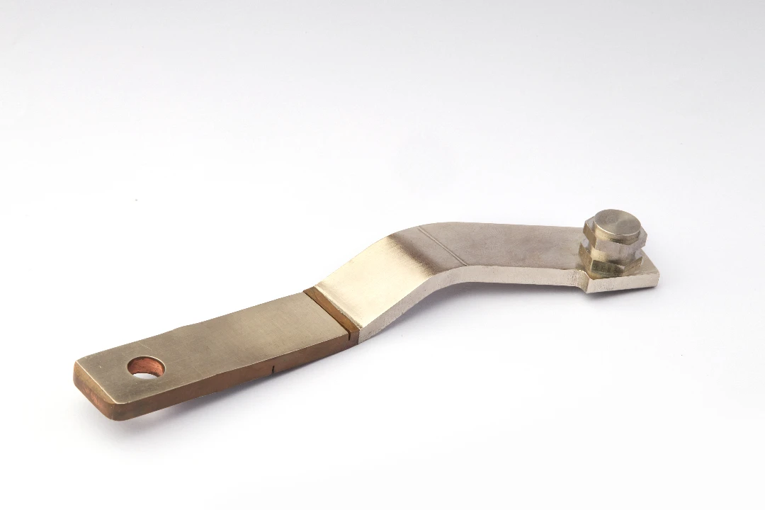
A copper busbar is a rigid or semi-rigid conductor—often a flat bar, stamped profile, or formed part—that distributes power among cells, modules, contactors, fuses, current sensors, and high-voltage junctions. In battery packs, busbars frequently include features like precision holes/slots, embossed areas, controlled bend radii, and alignment tabs to support assembly accuracy and repeatability. These features are not cosmetic; they reduce assembly risk and improve electrical consistency across high-volume builds.
Traditional busbar systems have long been used in electrical distribution, with definitions describing busbars as bar-shaped conductors that can be exposed or enclosed and incorporate joints and take-off points. That same concept is simply “compressed” into the tighter, harsher environment of an EV pack.
Why copper remains the default choice
Copper’s electrical conductivity at room temperature is commonly referenced around 58 MS/m for annealed copper (often discussed in the context of the International Annealed Copper Standard, IACS). This is one reason copper busbars can achieve target resistance in compact geometries, helping designers manage both voltage drop and heat generation.
Copper also offers practical benefits for manufacturing and assembly. It can be stamped, formed, brazed, welded (with the correct process controls), plated, and integrated with insulation systems to meet both electrical and mechanical requirements.
Copper grades and specifications you should actually care about
For procurement and quality alignment, it helps to anchor material selection to recognized specifications. For example, ASTM B187/B187M establishes requirements for copper conductor bars, rods, and shapes used in electrical (bus) applications, which is directly relevant when you are buying copper bar stock intended to become a battery busbar.
In practice, your grade choice affects conductivity, formability, joining behavior, and cost. A capable supplier should be able to recommend the right copper grade and temper for your forming steps and joint design—not just quote “copper” as a generic material.
Key Design Requirements for Battery-Pack Copper Busbars
Current rating, temperature rise, and realistic margins
A busbar design starts with current, but it must end with temperature. You can estimate resistance from geometry and material properties, but the real-world temperature rise depends on installation, airflow, insulation, nearby heat sources, and joint quality. That’s why serious programs treat busbar sizing as an iterative loop: electrical target → thermal verification → mechanical verification → manufacturability check.
Design guides for copper busbars emphasize comparing electrical and mechanical properties and understanding how conductor choice impacts performance. This is particularly relevant when you are balancing compact copper sections against heat dissipation and allowable temperature rise in enclosed spaces.
Joint reliability is often the real failure point
Many field issues don’t come from the straight section of the busbar. They come from the interfaces: bolted joints, welded tabs, brazed transitions, or sensor interfaces. These locations concentrate current, heat, vibration stress, and assembly variability, so tolerances, flatness, plating, and contact pressure matter.
A high-quality copper busbar supplier should be able to control hole quality, burr direction, flatness, and forming springback, because these factors directly affect joint contact resistance and long-term stability.
Mechanical constraints—vibration, fatigue, and assembly tolerance stack-up
Battery packs experience vibration from road inputs plus thermal cycling from operation and charging. Over time, that combination can loosen fasteners, degrade interfaces, and stress formed features. A robust busbar design uses appropriate bend radii, avoids stress risers, and accounts for tolerance stack-up so the part assembles consistently without forced fits.
This is where precision tooling and controlled forming processes matter. If your busbar geometry requires repeatability at scale, progressive stamping dies and well-managed forming steps can outperform “one-off” fabrication methods in consistency and unit cost.
Insulation coordination and high-voltage safety interface
Even if the busbar itself is bare copper, it must integrate with insulation films, covers, overmolds, or separators. Voltage class requirements influence creepage/clearance decisions and the way conductive parts are exposed (or not exposed) during service. ISO 6469-3 is one of the standards commonly referenced for EV electrical safety requirements, and it shapes how pack designers think about protection against electric shock and thermal incidents.
A supplier who understands these constraints can propose busbar edge treatments, insulation interfaces, and inspection methods that reduce risk in validation and certification.
Corrosion, fretting, and plating strategy
Copper oxidizes, and interfaces can degrade under micro-motion (fretting). In battery packs, you often need a plating strategy aligned with your joining method and mating materials. The “right” finish depends on whether you are bolting to aluminum, welding to nickel-coated tabs, or interfacing with sensor shunts and contactors.
This is not a one-size-fits-all decision. A production-minded approach defines where plating is required, what thickness range is needed, and how masking or selective plating is handled to control cost.
Architecture Options—Solid, Flexible, and Laminated Busbars

Solid stamped-and-formed copper busbars (most common in packs)
Solid busbars are cost-effective and mechanically stable, especially when designed for stamping and forming. With the right die design, you can integrate locating features, controlled bends, and repeatable hole patterns that speed assembly and reduce quality escapes. This approach is ideal for high-volume battery modules where takt time and repeatability are critical.
At JUMAI TECH, stamping expertise and precision die capability can be leveraged to keep geometry consistent across large builds, supporting stable joint resistance and predictable assembly fit.
Flexible copper busbars for movement, tolerance, and vibration isolation
Flexible designs—often layered copper foils—help absorb tolerance stack-up and thermal expansion, reducing stress on joints. They’re valuable where components move relative to each other, or where vibration isolation improves long-term reliability. Flex solutions are also helpful in tight packaging zones where a rigid busbar would force sharp bends or create assembly interference.
A good sourcing strategy is to use rigid copper busbars where structure and repeatability are needed, and flexible sections only where they deliver clear reliability or assembly benefits.
Laminated busbars for low inductance in high-power switching zones
Where fast switching and high di/dt are involved (such as inverter/DC-link areas), laminated structures can reduce loop inductance and help manage EMI and voltage overshoot. Even if your main battery module uses solid busbars, you may need laminated solutions in the high-frequency power electronics path. This is especially relevant as charging speeds increase and power electronics become more compact.
The key is to treat busbar architecture as part of the electrical system—not a late-stage mechanical bracket.
Material Choices That Make or Break a Copper Busbar Program
Start with recognized material specifications (so everyone speaks the same language)
When your busbar becomes part of a safety-critical EV battery pack, the material callout can’t be vague. Using established standards—such as ASTM B187/B187M for copper conductor bars, rods, and shapes—helps align expectations between design, purchasing, and manufacturing, especially when you scale from prototype to production.
A clear material specification also reduces the risk of “silent substitutions” that can change conductivity, formability, or joining behavior. That’s one of the simplest ways to avoid validation surprises later in the program.
Copper conductivity, IACS, and why “almost 100%” matters
Copper’s high conductivity is a major reason it remains the default busbar choice. Many engineering references express conductivity in %IACS, where 100% IACS corresponds to ~58 MS/m at 20°C (commonly cited around 58.108 MS/m).
In practice, higher conductivity helps you hit resistance and temperature targets with less cross-section, which can improve packaging and reduce hotspot risk. It also gives you more design freedom for features like windows, slots, and bends without over-inflating copper volume.
Temper and formability—your die and your bend radii will care
Even when two copper grades look similar on paper, temper can change how they behave during stamping and forming. A busbar that needs multiple bends, emboss features, or tight position tolerances may require a temper that supports repeatable forming without cracking or excessive springback. ASTM B187/B187M includes temper conditions that are often referenced when sourcing copper intended for conductor applications.
From a manufacturing viewpoint, the best busbar designs are the ones that control strain in forming steps. That means appropriate bend radii, smart grain direction planning, and avoiding stress risers around holes and sharp corners.
Surface finish and plating strategy—choose based on the joint, not aesthetics
A copper busbar’s performance is often decided at the interface: bolted joints, welded tabs, and sensor or fuse connections. Over time, joint resistance can increase due to surface film growth and other interface effects, so finish strategy matters for long-term reliability.
The right approach is to define finish zones based on function. For example, you may need plating or controlled surface conditions only where the busbar mates to another conductor, while leaving non-critical zones as bare copper to control cost and maintain formability.
EV Pack Architecture Trends That Influence Busbar Design
400V vs 800V systems—why voltage architecture changes busbar constraints
A move from ~400V-class to ~800V-class architectures can reduce current for the same power (P = IV), which can ease conductor sizing and reduce resistive losses. Industry discussions and technical papers describing 800V transitions highlight this efficiency advantage and its impact on component packaging and thermal performance.
This doesn’t mean busbars become “easy” at higher voltage. Higher voltage increases insulation coordination sensitivity, creepage/clearance requirements, and packaging constraints around safety barriers.
Insulation coordination drives geometry—creepage and clearance aren’t optional
For high-voltage equipment, creepage and clearance are part of the engineering baseline. IEC 60664-1:2020 is widely referenced for insulation coordination guidance (including clearances, creepage distances, and solid insulation criteria) for equipment up to AC 1000 V or DC 1500 V.
In EV battery pack design, these rules influence edge distance, cover interfaces, fastener selection, and even the shape of a copper busbar cutout. If you design the busbar first and “add insulation later,” you usually pay for it in redesign cycles.
Safety standards shape electrical interfaces and validation expectations
For electrically propelled road vehicles, ISO 6469-3:2021 specifies electrical safety requirements related to protection against electric shock and thermal incidents for relevant high-voltage circuits.
In many markets, regulations such as UNECE Regulation No. 100 (R100) also drive requirements around insulation resistance and protection concepts for high-voltage buses and energy storage systems.
If your copper busbar design is intended for global OEM programs, you want a supplier who understands how these requirements translate into practical decisions: edge treatment, insulation interfaces, fastener access, and inspection criteria.
Busbar Resistance, Contact Resistance, and Why Joints Deserve Extra Engineering

Busbar geometry affects electro-thermal behavior in packs
It’s not only “how much copper” you have, but where it is and how it’s routed. Research studying busbars in battery systems shows that busbar thickness, length, and material can influence thermoelectric behavior in packs, which becomes more noticeable at higher current levels.
That’s why a good copper busbar design process includes both electrical and thermal thinking. You want a shape that routes current efficiently without creating localized hotspots near constrictions, bends, or interfaces.
Contact resistance can dominate heat generation at real-world interfaces
In many packs, the straight busbar section is fine; the joint becomes the problem. Studies and technical reports note that contact resistance can increase temperature rise, and poor joints can contribute to severe reliability risks in power systems.
A production-minded busbar program therefore treats joint design as a controlled feature set. That includes flatness targets, burr control, contact area definition, and torque/pressure strategy for bolted connections.
Reliability is time-based—surface films and micro-motion are real
Joint performance changes over time due to chemical reactions, surface films, and micro-motion effects. Technical documentation on busbar joints describes how contact/joint resistance can increase with time due to impurity film build-up, which is exactly why plating and controlled interface design are so important.
In EV packs, vibration and thermal cycling can accelerate interface degradation. The best way to reduce risk is to design joints that are tolerant of real manufacturing variation while keeping contact resistance stable.
Manufacturing a Custom Copper Busbar—From DFM to First-Off Samples
DFM starts with your electrical intent and ends with your tooling reality
A “print-perfect” busbar that cannot be stamped consistently is a schedule trap. DFM (design for manufacturing) should translate electrical targets (resistance, inductance, temperature) into geometry your die can repeat—especially for hole quality, slot radii, and bend locations.
At JUMAI TECH, this is where precision stamping die expertise becomes part of the busbar product. When tooling is designed around stable forming and consistent datum strategy, first-off samples are more likely to match the intent without multiple rework loops.
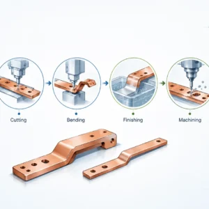
Typical production flow for stamped-and-formed copper busbars
A high-volume copper busbar program often follows a flow like: material incoming → blanking/stamping → forming/bending → deburr/edge conditioning → cleaning → plating (full or selective) → inspection → packaging with traceability. Each step needs defined controls, because copper is conductive, soft enough to mark, and sensitive to burrs at interfaces.
This is why “cheap processing” can get expensive quickly. A single uncontrolled burr can raise contact resistance or damage insulation films, and a single inconsistent bend can break assembly fit in a battery module line.
Tooling and process capability are what scale prototypes into production
Many projects can produce a prototype busbar. Fewer can hold the same geometry at production volume with predictable lead times and controlled variation, because that requires process capability and stable tooling.
That’s why we treat progressive tooling, forming steps, and in-process checks as part of the solution—not as an afterthought. If your EV or battery pack program is moving toward SOP, this discipline is what keeps yield stable.
What we typically need from you to quote accurately (and avoid surprises)
For a fast, accurate quotation and DFM review, provide 2D drawings + 3D model, target material/temper, finish requirements, functional dimensions, and any special joint interface notes. If you have current/temperature targets or a known hotspot area, include that too, because it can influence local geometry recommendations.
If you don’t yet have full requirements, we can still start with a manufacturable baseline. The goal is to get you first-off samples that represent a realistic production path—not a one-time handmade part.
Validation and Quality—How EV Programs De-Risk Copper Busbars
Dimensional inspection isn’t enough; functional checks matter
Dimensional checks (hole position, flatness, bend angles) are essential, but EV pack reliability also depends on surface, burr direction, and interface quality. A busbar can “measure right” and still create heat if the joint surface condition is wrong.
That’s why robust programs add functional validation thinking: joint resistance targets, assembly fit verification, and controlled surface treatment in critical zones.
Designing with standards in mind reduces late-stage test failures
When the pack needs to demonstrate electrical safety, it helps if the busbar system was designed from day one with insulation coordination expectations (IEC 60664-1) and vehicle electrical safety requirements (ISO 6469-3) in mind.
And where UNECE R100 applies, aligning protection and insulation resistance expectations early reduces downstream rework.
Battery safety test ecosystems influence documentation expectations
OEMs and Tier-1s frequently align their internal validation plans with external safety frameworks. For example, UL 2580 is commonly discussed as a safety evaluation standard for EV batteries, and testing organizations describe it as covering electrical, mechanical, thermal, and environmental evaluations.
Even if your copper busbar itself isn’t “certified,” it lives inside a certified system. That reality drives traceability, change control, and consistent manufacturing records.
Why Choose JUMAI TECH for Custom Copper Busbar Projects

Built for EV realities: repeatability, scalability, and tight interfaces
EV packs punish variability. A busbar that shifts by a fraction of a millimeter can create assembly stress, misalignment at contactors, or inconsistent joint pressure across a module. Our approach prioritizes stable datums, repeatable forming, and die-driven consistency so your assembly process stays predictable.
We also understand that programs evolve. That’s why we focus on a path that works from prototype through ramp, instead of optimizing only for the first sample.
Precision stamping dies + formed copper = faster learning cycles
Because we support precision die development and stamping-driven production, we can shorten the loop between design feedback and manufacturable geometry. That usually means fewer “trial-and-error” prototype turns and a clearer plan for scaling.
If your project includes related formed components, brackets, or deep-drawn parts around the busbar system, coordinating these together can also reduce stack-up risk in pack assembly. JUMAI TECH’s broader forming background helps you keep the full mechanical context in view.
Supplier mindset: DFM support, not just build-to-print
A busbar supplier should flag risks before they become failures. We proactively review: bend radii vs temper, hole-to-edge distances, burr control needs, selective plating feasibility, and tolerance stack-up—so your copper busbar design survives real manufacturing and real pack assembly.
The result is a part that performs electrically and assembles smoothly. That’s the combination EV and battery pack teams care about most.
Practical FAQ for EV & Battery Pack Copper Busbars
“How do I know if my busbar design will run hot?”
If you can share your current peaks (drive + charge), we can suggest geometry adjustments that reduce localized heating without dramatically increasing copper mass.
“Should I use copper or aluminum?”
Many packs also use a mixed strategy: copper where electrical density and joints are critical, and aluminum where structure and cost dominate. The best answer depends on your interface design and validation constraints.
“What is the biggest hidden risk in busbar sourcing?”
Those are exactly the risks that disciplined tooling, process control, and inspection planning are meant to eliminate.
Request a Quote for Custom Copper Busbar Solutions
In EV programs, speed is important—but repeatability is what wins. Let’s build a copper busbar solution that performs on the bench, on the line, and in the field.