Switchgear OEMs live and die by reliability, repeatability, and compliance. When the main circuit carries thousands of amps and must survive thermal cycling and fault events, the copper busbar stops being “just a conductor” and becomes a core mechanical and safety component in the assembly.
This marketing guide is written for engineering, sourcing, and quality teams who need an MT (medium-tension / medium-voltage context) copper busbar assembly that installs fast, stays cool, and holds up under short-circuit forces. You will learn the design decisions that matter most, the common verification routes, and the DFM habits that reduce cost without compromising performance.
What “MT Copper Busbar” Means in Switchgear OEM Programs
“MT copper busbar” is often used in global procurement to describe copper busbars designed for medium-voltage switchgear ecosystems—including metal-enclosed gear, ring main units, and distribution lineups. Even when the busbar itself is part of a low-voltage compartment, the surrounding system may still demand MV practices: insulation coordination, robust bracing, and compartment-level safety concepts.
A practical MT copper busbar strategy starts by mapping your project to the standard family that your customers expect. For IEC-driven MV products, metal-enclosed switchgear assemblies commonly reference the IEC 62271 series, including IEC 62271-200:2021 for AC metal-enclosed switchgear and controlgear. IEC Webstore IEC 62271-200 explicitly covers prefabricated metal-enclosed assemblies for rated voltages above 1 kV up to and including 52 kV, which is why it often anchors MT switchgear specifications. IEC Webstore
For LV assemblies (or LV sections inside a lineup), IEC 61439 is often used for verification frameworks such as temperature-rise testing and routine checks, while IEC TR 60890:2022 provides a recognized method for temperature-rise verification by calculation in enclosures under defined conditions. IEC Webstore To avoid retesting, state in your specification which sections of the lineup follow IEC 61439 verification and which sections follow IEC 62271 expectations.
Start With Requirements That Actually Drive Copper Busbar Design
Before you pick a bar size, capture the numbers that truly constrain the design. A copper busbar that looks perfect in CAD can become a failure mode if assumptions around current, fault level, ventilation, or joining are vague.
Rated continuous current and the real duty cycle
Nameplate current is your starting point, but switchgear rarely operates in a vacuum. Harmonics, load cycling, ambient temperature, and enclosure airflow can change temperature rise dramatically, which is why early-phase sizing should always be verified against the real enclosure and duty cycle.
If you need a recognized calculation approach to align cross-functional teams before building prototypes, IEC TR 60890 describes how to estimate air temperature rise inside enclosures for LV assemblies and similar products. IEC Webstore The key benefit is not “perfect prediction,” but consistent assumptions that reduce late-stage surprises.
Short-time withstand and peak withstand current
Switchgear busbars must withstand both thermal I²t and electrodynamic forces during faults. In IEC practice, the rated short-time withstand current (Ik) and the rated peak withstand current (Ip) drive spacing, bracing, and joint design, and they influence test planning within the IEC 62271 family.
National adoptions of IEC 62271-1 describe how short-time and peak withstand tests are applied, including time requirements (for example, a peak withstand test time not less than 0.3 s is referenced in a BIS adoption of IEC 62271-1). Law Resource Even if your final compliance path is different, designing the copper busbar support system for the target fault energy and duration is non-negotiable.
Environmental and installation conditions
Humidity, coastal corrosion, contaminants, altitude, and ambient temperature affect whether bare copper is acceptable or whether plating and insulation are required. In MV gear, internal arc classification and enclosure accessibility can also influence compartment design decisions that indirectly shape busbar routing and protection.
For teams new to internal-arc terminology, Schneider Electric’s definition of AFLR accessibility types in IEC 62271-200 contexts is a helpful cross-functional reference. Accessibility type AFLR explained. Schneider Electric
Thermal Design: Current Density, Temperature Rise, and Hot-Spot Control
Thermal performance is where many copper busbar assemblies quietly fail. The conductor may be sized “big enough,” yet the joint is not, or the enclosure traps heat in a way that invalidates the initial spreadsheet.
Use ampacity references—but validate in your enclosure
Ampacity tables are useful for first-pass sizing, quoting, and sanity checks. The Copper Development Association (Copper.org) provides accessible busbar ampacity references and documents typical assumptions such as ETP copper bus bar at 100% IACS conductivity and references to ASTM B187 for busbar products: Copper busbar ampacity reference. copper.org Use the tables for early sizing, then validate the final copper busbar design in the real compartment, because enclosure airflow and phase spacing can dominate the outcome.
However, switchgear OEMs should treat ampacity tables as a starting point, not an approval. Enclosure geometry, phase spacing, partitions, cable terminations, and natural convection paths can raise or lower temperature rise significantly, especially in compact designs.
Why joints run hotter than straight lengths
The highest temperature in a copper busbar assembly is frequently at a bolted joint, a transition to a flexible connector, or a dissimilar-metal interface—not in the middle of a straight bar. Joint heating is driven by contact resistance, surface condition, clamp force stability, and the tendency for oxidation or contamination to increase micro-ohms over time.
That means thermal design is inseparable from mechanical design. If you only size the bar cross-section and ignore joint engineering, you may pass initial testing and still see field failures after years of cycling.
Temperature-rise limits: design with margin, not with hope
Temperature-rise limits vary by standard family and component location. For IEC 61439-type guidance, some published test instructions and notes referencing IEC/EN 61439-2 cite that, assuming other criteria are met, a maximum temperature rise of 105 K for bare copper busbars and conductors is permissible in certain contexts. lovag.net+1
In North American practice for low-voltage switchgear, many product documents reference a 65 °C temperature rise above 40 °C ambient as a basis for bus ratings. For example, Siemens documentation and Eaton technical data reference a 65 °C rise basis for bus ratings in their switchgear families. Siemens+1 This is not a substitute for your project specification, but it is a practical reason to design joints and ventilation with conservative margin.
Practical hot-spot reduction techniques
The easiest hot-spot reductions often come from geometry and process control, not from adding copper everywhere. Wider contact pads, shorter current paths through the joint stack, and controlled surface flatness can reduce resistance without adding major mass.
Thermal improvement also comes from consistency. A copper busbar program with stable plating thickness, controlled oxidation prevention, and repeatable torque procedures typically runs cooler than a “bigger” busbar with uncontrolled joint variability.
Electrical Design: Resistance, Inductance, AC Effects, and Fault Forces
Electrical design is not just about cross-sectional area and amps. At high current, geometry influences impedance, losses, and short-circuit behavior, and those effects are magnified by tight packaging.
Material resistivity and conductivity assumptions
When you specify a copper busbar, you are also specifying electrical properties that drive I²R losses and temperature rise. Copper.org explains the International Annealed Copper Standard (IACS) and notes that modern commercially pure copper can achieve conductivity slightly above the historical 100% IACS reference. IACS conductivity explanation. copper.org
Use these published references as a baseline when comparing copper grades, tempers, and alloys. If your design depends on a narrow margin, specify minimum conductivity (or maximum resistivity) explicitly in your procurement documents.
Layout: inductance and electromagnetic coupling
In switchgear lineups, phase layout affects both losses and electrodynamic forces. Symmetric, compact phase arrangements can reduce loop inductance, but tight spacing increases proximity effect and can create uneven heating if phase geometry is inconsistent along the run.
A robust approach is to prioritize symmetry and repeatability. If the physical layout changes across product variants, treat each variant as a unique thermal-electrical system and verify it, rather than assuming it will be similar.
If you build for North American MV metal-clad switchgear expectations, continuous current ratings and bus design practices are often discussed in OEM technical literature tied to ANSI/IEEE approaches. Siemens, for example, notes that continuous current ratings of bus bars in MV metal-clad switchgear are determined by ANSI requirements in its TechTopics series. Siemens TechTopics No. 17. Siemens
Short-circuit electrodynamic forces and bracing strategy
During a fault, parallel conductors can attract or repel with high force. Supports, insulators, and the copper busbar itself must handle these forces without plastic deformation, joint loosening, or insulation cracking.
This is why bus support systems are as important as conductor cross-section. A busbar design that “survives” electrically but allows supports to crack or bolts to loosen will still fail the program, either in testing or in service.
Copper Selection: Grades, Tempers, and When to Use Plating
Copper is not a single material in procurement reality. “Copper busbar” can mean different grades, oxygen content, and mechanical properties depending on the specification.
Specify recognized material standards
For many global and North American programs, ASTM B187/B187M is a widely used specification for copper conductor bars, rods, and shapes for electrical (bus) applications. ASTM International | ASTM Using a recognized standard reduces disputes at incoming inspection and improves consistency across multi-site supply chains.
For IEC-oriented procurement, you may still reference ASTM for material definition while controlling the verification path via IEC tests. The point is to avoid “mystery copper,” especially in multi-supplier scenarios.
Balance conductivity with mechanical stability
Annealed copper offers excellent conductivity and formability, while harder tempers can improve stiffness and reduce creep under sustained clamp loads. The best choice depends on whether your design relies on the busbar for structural stiffness, the tightness of bend radii, and how much thermal cycling the joint stack will experience.
A practical tip is to treat temper selection as a joint-reliability decision. If clamp force loss over time is a risk, a busbar system with better mechanical stability can reduce long-term micro-ohm drift.
Tin, silver, and nickel: surface engineering for reliability
Plating is typically chosen for contact performance, corrosion resistance, and assembly repeatability. Tin plating is common for corrosion resistance and solderability; silver plating is often used in high-current joints to reduce contact resistance when surfaces are properly handled and kept clean.
Plating should never be treated as cosmetic. Specify thickness, adhesion expectations, post-plate handling, contact interface compatibility, and the allowed rework method, because field polishing or aggressive cleaning can destroy the very properties plating was meant to provide.
Geometry and Insulation Coordination Inside Switchgear Compartments
Switchgear packaging constraints push designers toward tight layouts. The trick is to keep compactness without introducing insulation risk or assembly headaches.
Clearances, creepage, and edge control
In MV compartments, clearances and creepage distances depend on system voltage, pollution degree, and insulation class. Even in LV compartments within an MV lineup, the copper busbar may be near grounded metal or insulating barriers, so burrs and sharp edges can create localized stress or tracking risk.
A disciplined mechanical finishing process matters. Deburring, edge rounding, and consistent corner radii reduce insulation problems and also improve coating and heat-shrink fit.
Bending radii, springback, and dimensional repeatability
Tight bends look space-efficient but can create cracking risk in plated layers or introduce residual stress that relaxes under heat. Springback variation is also a hidden cost, because it turns assembly into a manual “fit and tweak” process that OEMs hate.
For MT copper busbar assemblies, controlled bending supported by forming dies and defined radii improves dimensional repeatability. It also reduces the chance that a bar “walks” during installation and violates phase clearance at the worst possible location.
Insulation options: boots, sleeves, and coatings
Heat-shrink tubing and molded boots can provide robust insulation at joints and terminations, while epoxy or powder coatings can protect surfaces and reduce corrosion. The best choice depends on assembly sequence, serviceability, thermal dissipation, and whether inspection needs to see the copper surface.
If you require insulation, specify what must remain exposed for electrical contact, and define masking geometry. A vague masking requirement is a common cause of rework and inconsistent contact quality.
Joint Engineering: The Difference Between “Conducts” and “Lasts”
The joint is the most common weak link in a copper busbar system. Designing the joint as a first-class engineering element is one of the fastest ways to reduce warranty risk.
Bolted joints: contact pressure and stability over time
Bolted joints remain the default because they are serviceable and familiar to switchgear OEMs. However, they only perform well when torque control, washer stacks, flatness, and surface cleanliness are consistent.
A good MT copper busbar design uses standardized joint footprints, avoids long current paths through bolt shanks, and includes anti-rotation and alignment features. These details reduce assembly variation and reduce the risk of “good units” and “bad units” in the same production batch.
Joint surface preparation and oxidation control
Copper oxidizes, and oxides increase contact resistance. If your process relies on field cleaning, you are accepting variability, because cleaning aggressiveness differs by operator and by plant.
Instead, define a controlled surface state: plating, protective films, packaging, and a clear assembly window. The goal is that the copper busbar arrives at the OEM line in the same surface condition you validated in qualification testing.
Brazing and welding: when permanent joints are worth it
Permanent joints can eliminate some contact-resistance variability, but they introduce process control requirements and inspection needs. Brazed laminations or welded stacks can be excellent in high-volume OEM programs if metallurgy, cleanliness, and post-process distortion are controlled.
Use permanent joining when serviceability is less important than consistent low resistance and compact packaging. When serviceability matters, consider hybrid designs where permanent joints are internal and bolted interfaces remain accessible.
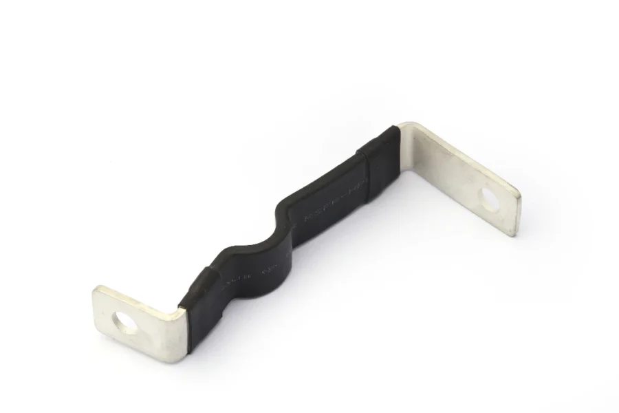
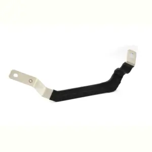
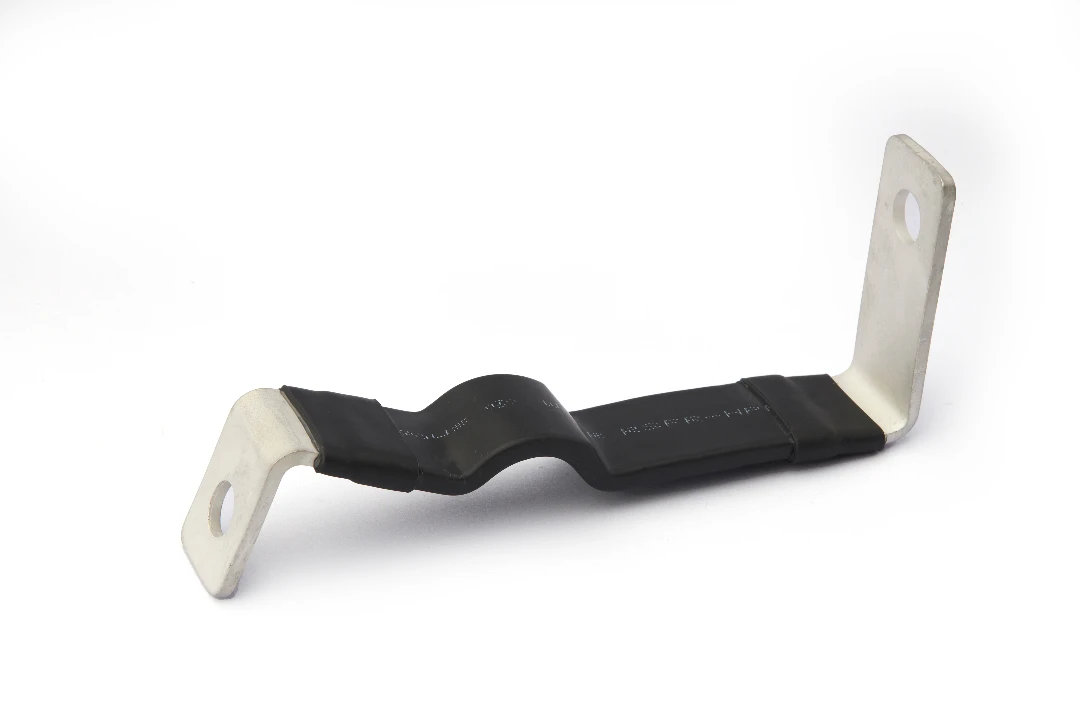
Flexible links and thermal expansion management
Even in switchgear, thermal expansion can loosen joints if the busbar system is over-constrained. Flexible laminated connectors or braid links can isolate movement between compartments and reduce stress on insulators, while also helping tolerance management in multi-bay lineups.
Flexible sections are not extra parts for comfort. They can prevent cracking, reduce support stress, and improve long-term stability of clamp force at critical interfaces.
Manufacturing for Repeatability: Stamping, Forming, and Deep-Drawn Integration
A switchgear OEM does not buy a copper busbar because it looks nice. They buy it because it fits the first time, installs fast, and performs consistently across thousands of panels.
Precision stamping and forming for high-volume busbars
For repeatable MT copper busbar production, precision stamping dies and controlled forming operations reduce part-to-part variation. Stamped features like slots, pilot holes, alignment tabs, and controlled reliefs can eliminate secondary machining and prevent “field drilling” on the OEM assembly line.
Tooling quality is also electrical quality. Die design influences burr direction, edge geometry, and flatness—each of which affects insulation, coating, and joint stability over time.
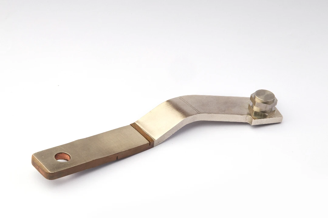
Deep-drawn components that protect and simplify
In many switchgear designs, busbars interface with shield covers, terminal housings, current-transformer brackets, or insulation barriers made from formed metal. Deep-drawn components can provide robust protection and help manage electric-field stress by offering smooth, continuous surfaces.
When the copper busbar and deep-drawn hardware are developed together, OEMs often gain fewer fasteners, fewer tolerance stack-ups, and shorter assembly time. That integration is one of the most underused levers in cost reduction without compromising performance.
Surface finishing and cleanliness as a defined process
Contact surfaces are performance surfaces. If a copper busbar arrives with residue, oxidation, or inconsistent plating, no torque specification will reliably rescue the joint.
Define packaging, protective films, and handling requirements explicitly. Treat “as-installed surface condition” as a requirement, because it is exactly what determines micro-ohm stability and long-term temperature rise.
Verification and Test Planning: Build Evidence Into the Design
Switchgear OEMs care about test evidence, not marketing language. Your copper busbar design should be built to pass routine checks and to generate documentation that quality teams can trust.
Temperature-rise verification by test or calculation
Many programs begin with calculation and finish with verification testing. IEC TR 60890 provides a recognized method for air temperature-rise calculation inside enclosures for LV assemblies under defined assumptions, and it helps engineering teams align on constraints early. IEC Webstore
Even when the final verification is by test, a disciplined calculation workflow reduces iterations. It also makes design reviews more productive because discussions focus on inputs rather than gut feel.
For LV assembly teams building IEC documentation packages, ABB provides a practical guidance document on constructing LV assemblies in compliance with IEC 61439-2 routine verifications. ABB IEC 61439-2 routine verification guidance (PDF). ABB Library
Short-circuit withstand evidence: test, calculation, or both
Short-circuit withstand performance is often demonstrated by test reports, validated calculations, or a combination, depending on the program and standard path. IEC 62271 frameworks and related industry documents emphasize that busbars and their supports must withstand mechanical stresses during short circuits, which is why support design is a core deliverable, not an afterthought. Law Resource+1
If your design is intended for internal-arc classified gear, ensure that bus routing, barriers, and fasteners do not create secondary hazards during an event. A technical overview of internal arc considerations in IEC 62271-200 contexts can be found in industry white papers such as Roxtec’s discussion of internal arc and arc-flash. Internal arc & arc-flash white paper. Roxtec Global
Routine inspection: dimensional, plating, and resistance checks
A robust program includes inspection criteria tied to function. Dimensional checks should focus on interface-critical features (hole patterns, pad flatness, bend angles, and key clearances), while plating inspection should verify thickness and adhesion where contact is made.
For high-volume programs, micro-ohm resistance checks at representative joints can catch drift early. The point is not to inspect every joint forever, but to detect process drift before it becomes a field issue.
DFM Habits That Cut Cost Without Sacrificing Performance

Cost is not just copper price per kilogram. It is also labor, scrap, rework, test failures, and the cost of late engineering changes.
Create modular busbar families instead of one-off parts
When switchgear OEMs build multiple ratings, they value modularity. A family of copper busbar parts that share a common joint footprint and scale by adding laminations or parallel bars reduces inventory complexity and simplifies qualification.
This approach also improves supply resilience. If two parts share hardware, pads, and process routes, the line is less vulnerable to shortages of one “unique” fastener or one unique plated variant.
Design for standard hardware and standard torque tools
Avoid exotic fasteners when standard solutions meet the requirement. Standardizing bolt sizes, washer stacks, and torque values reduces assembly time and lowers the chance of field mistakes, especially when OEMs build in multiple factories.
Standardization also improves serviceability. End users and service teams can maintain the switchgear more reliably when interfaces are consistent and predictable.
Plan plating and insulation as part of the process route
Plating and insulation steps can dominate lead time if they require outside processing or special handling. Integrate these steps into your schedule and specify what surfaces must be plated, masked, or left bare.
A clear process route also makes quoting accurate. It prevents “surprise” engineering changes when the first prototypes reveal that an insulating boot cannot be installed after a certain fastener is already torqued.
A Simple MT Copper Busbar Design Workflow That Works
A repeatable workflow reduces redesign cycles and keeps the program on schedule. It also helps align engineering, sourcing, and quality on the same set of deliverables.
Step 1: Define electrical and mechanical envelopes
Start with rated current, ambient assumptions, allowable temperature rise targets, and the fault level (Ik and duration, plus peak current). Then define the mechanical envelope: compartment dimensions, phase centers, required clearances, and installation sequence constraints.
Documenting the installation sequence early is important. Many busbar designs fail not because the part is wrong, but because it cannot be installed with the tools available in the compartment.
Step 2: Select copper grade and surface system
Choose the copper grade/temper using a recognized material standard such as ASTM B187/B187M for conductor bars. ASTM International | ASTM Then choose the surface system: bare copper, tin plating, silver plating, or an insulated/coated strategy, with packaging and handling requirements.
Treat surface condition as a design input, not as a supplier detail. Your joint performance depends on it.
Step 3: Size and route the copper busbar with joint-first thinking
Size the bar for continuous current and enclosure conditions using conservative assumptions. Then design joints and transitions as the primary constraint, ensuring pad area, bolt patterns, and access for torque tools.
Finally, route the busbar to minimize unnecessary bends, avoid tight corners near insulation barriers, and maintain symmetric phase geometry. The more symmetric your layout, the easier it is to predict thermal and electrical behavior.
Step 4: Engineer supports and insulation as a system
Design bus supports for both normal operation and fault forces, including the mechanical behavior of insulators, brackets, and fasteners. Verify that insulating boots, sleeves, and barriers can be installed in the planned sequence, and that they do not interfere with torque access.
A busbar “system” includes the support system. If your RFQ only specifies copper parts and ignores supports, you are likely to get design drift between suppliers.
Step 5: Verify, document, and lock the process
Use calculation tools and/or prototype tests to validate temperature rise and joint stability. Capture the final process route, inspection plan, torque values, packaging method, and labeling so that quality can enforce consistency across shipments.
This is where programs become scalable. The best busbar design is the one that the supplier can reproduce every month without heroics.
Why Switchgear OEMs Choose JUMAI TECH for Copper Busbar Programs

A successful MT copper busbar program needs more than machining capacity. It needs tooling knowledge, forming control, and a manufacturing system that can hold tolerances batch after batch while keeping contact surfaces clean and consistent.
JUMAI TECH supports switchgear OEMs with custom copper busbar fabrication, precision stamping die capability, and deep-drawn component integration. That combination helps OEMs reduce supplier interfaces, launch faster, and keep performance consistent across different product ratings and lineup configurations.
If you share your drawings or performance targets, our engineering team can propose optimized bar geometry, joint footprints, plating options, and DFM improvements. We can also support prototyping, scalable production, and inspection documentation so your program can move from design to mass production with fewer iterations.
A Practical Checklist for Your Next MT Copper Busbar RFQ
A well-structured RFQ accelerates quoting and reduces redesign cycles. It also helps your supplier deliver the right copper busbar the first time, not after three rounds of clarifications.
Provide rated current, short-time withstand (kA and duration), peak withstand, ambient assumptions, enclosure constraints, insulation requirements, and your target standard family (IEC or IEEE/ANSI). Include interface drawings showing mating pads, bolt patterns, and allowable tolerances, and specify copper grade/temper using recognized standards such as ASTM B187/B187M. ASTM International | ASTM
Finally, define how parts must be packaged to protect contact surfaces, because shipping damage or oxidation can erase the electrical margin you designed in. When the RFQ is complete, the supplier can focus on engineering value—rather than spending weeks guessing what you meant.