Welds and assembly operations often look “cheap” on a CAD model—but in real OEM production they can become the biggest drivers of cost, lead time, and quality risk. Every weld adds fit-up, fixturing, skilled labor, heat input distortion, inspection, and sometimes rework. Every assembly step adds handling, line balancing complexity, and variability.
That’s why more OEM teams are redesigning welded fabrications into deep drawn stamping parts: a seam-free, repeatable, one-piece formed shell that can replace multiple brackets, covers, cups, or housings. Done correctly, deep drawn stamping simplifies the bill of materials (BOM), reduces touch time, and improves reliability—while keeping the supply chain scalable for high-volume programs.
Table of Contents
Why welds and assembly steps are so expensive in OEM programs
Welding is not just “arc time”
A weldment’s cost is rarely just the time the torch is on. The total effort includes part prep, cleaning, beveling, clamping, tack welding, sequencing, post-weld cleanup, and sometimes straightening. When you add operator variability and access constraints, the “hidden” portion becomes unavoidable and hard to estimate early in design.
This is exactly why welding organizations publish dedicated costing guidance and stress that repair and rework can become disproportionately expensive when defects are discovered late. The Welding Institute (TWI) highlights how costly repair welds can be—especially when defects are detected after final assembly or after heat treatment. (TWI welding costs – continued)
Inspection and quality systems add recurring overhead
Many industries treat welds as special processes requiring documented controls, qualified procedures, and inspection plans. If your product falls under codes, customer specs, or high-reliability requirements, weld inspection can move from “spot check” to a program-level system.
International standards like ISO 3834 outline quality requirements for fusion welding and reinforce the reality that welding is a managed process—not a simple operation. (ISO 3834-1 overview)
Every assembly step multiplies variation
Assembly steps bring tolerance stack-ups, alignment tasks, and human factors. The more parts you assemble, the more opportunities you create for misalignment, missing fasteners, wrong torque, cosmetic damage, or mixed revisions. Even when each step looks small, the combined risk can drive higher scrap, more line stops, and more incoming inspection.
From a Design for Manufacture and Assembly (DFMA) perspective, reducing part count and simplifying assembly routinely produces large cost and time improvements across products and industries. (DFMA results and case studies)
What deep drawn stamping is and why it naturally eliminates welds
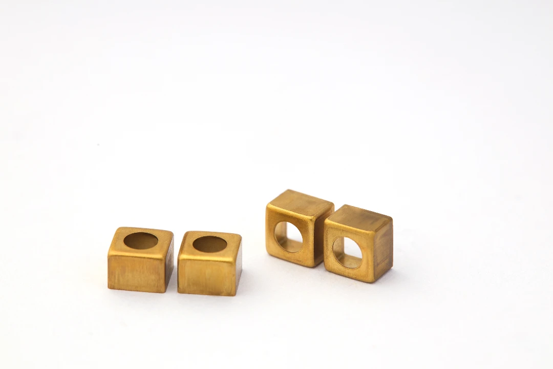
Deep drawing creates a one-piece shell instead of multiple plates
Deep drawn stamping forms a flat blank into a hollow shape using a punch, die, and blank holder. Because the material flows rather than being cut into multiple panels, you can produce cups, cans, housings, and enclosures as a single continuous piece—often eliminating seams entirely.
If you want a formal process explanation, ASM (a widely referenced materials authority) summarizes deep drawing mechanics and drawability fundamentals. (ASM Handbook: Deep Drawing overview)
Secondary operations can be built into the same production route
A smart deep drawn stamping plan doesn’t stop at “make a cup.” In one controlled route you can combine:
- Blanking / piercing
- Multiple draw stages
- Trimming and re-striking for shape control
- Piercing holes after draw (for positional accuracy)
- Flanging, beading, coining, embossing, and form features
When these features are created in tooling—rather than added later by welding or assembly—you reduce both direct labor and variation.
Tooling turns complexity into repeatability
Welded assemblies often rely on fixtures to “force” geometry into place. Deep drawing flips that logic: the die defines geometry, and process controls maintain it. That’s why deep drawn stamping is so attractive for OEMs targeting stable PPAP runs and multi-year production.
How deep drawn stamping replaces welded assemblies with integrated geometry
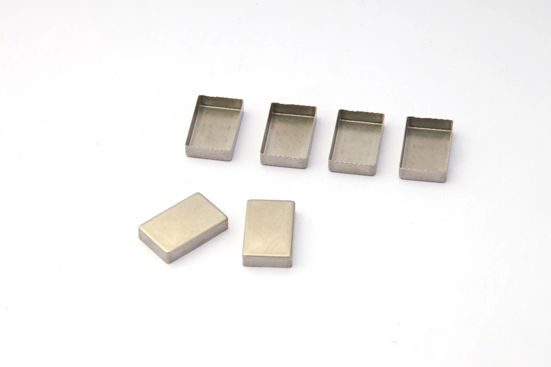
Turning multi-part weldments into single-piece components
Common candidates for conversion to deep drawn stamping include:
- Sensor housings and protective cups
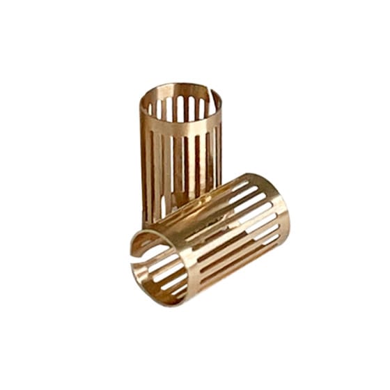
- Cylindrical sleeves and motor cases
- Battery covers, caps, and small enclosures
- Filter bowls and end caps
- Shield cans and EMI covers
If a part exists mainly to create a cavity, protect internals, or hold a seal, it is often a strong candidate. Instead of welding a tube to a plate and then adding brackets, a deep drawn shell can integrate the “tube + base + locating features” in one body.
Built-in features reduce brackets, fasteners, and alignment tasks
Features that usually require extra parts can often be created directly in the drawn body:
- Flanges for fastening or crimping
- Beads for stiffness (replacing ribs or welded reinforcements)
- Embossed bosses for locating or spacing
- Dimples as standoffs and repeatable assembly locators
Some deep draw specialists show how dimpling can simplify downstream alignment by acting as locators or standoffs—exactly the kind of feature that replaces assembly fiddling. (Example discussion: dimpling benefits)
Fewer joints means fewer leak paths and fewer fatigue initiators
When you remove weld seams, you also remove common failure initiation zones: HAZ-related distortion, porosity-related leak paths, and stress concentration at toes. For sealed or high-cycle parts, a seam-free geometry often improves reliability while reducing the inspection burden.
How deep drawn stamping reduces assembly steps on the factory floor
BOM reduction simplifies purchasing and kitting
A welded/assembled design creates a longer list of purchased or internally made components: plates, tubes, tabs, brackets, fasteners, and sometimes adhesives or sealants. Every line item requires sourcing, incoming checks, storage, and kitting.
A deep drawn redesign can collapse that into:
- 1 deep drawn shell
- Optional gasket/seal element
- Optional secondary hardware (sometimes eliminated too)
That BOM simplification reduces procurement touches and reduces the chance of line stoppages due to missing components.
Eliminating fixtures and “fitting work”
Welded assemblies often depend on fixtures to hold parts in position and prevent distortion. But fixtures don’t eliminate variation—they manage it. Once you switch to deep drawn stamping, the forming tool becomes the geometry master, and downstream assembly often becomes “place and fasten” rather than “measure, align, clamp, weld, re-check.”
Lower WIP and faster flow
Assembly-heavy products accumulate work-in-process (WIP) between stations. Each station adds queues and scheduling complexity. Reducing welds and assembly steps typically shortens routing, makes cycle time more predictable, and improves on-time delivery performance.
Quality and reliability advantages of reducing welds
Welding quality controls are real—and they are not free
Many OEMs require formal welding quality controls, documentation, and inspection. ISO 3834 exists because welding outcomes depend on process controls, personnel competence, and inspection planning. (ISO 3834-1 overview)
Even when requirements are “lighter,” the ecosystem around welding—training, procedure qualification, inspection staffing—adds recurring cost. AWS also discusses how quality systems and in-process controls contribute to weld quality outcomes. (AWS quality welding discussion)
Fewer welds often means fewer inspections and fewer escapes
If you remove welds, you typically reduce:
- Visual inspection points
- NDT requirements (where applicable)
- Rework loops
- Risk of “late discovery” defects
TWI’s welding cost guidance emphasizes how expensive repair can become when access is difficult or the product is already assembled. (TWI welding costs – continued)
More consistent geometry supports automation
Deep drawn stamping parts, when tooled correctly, are highly repeatable. That repeatability supports automated assembly, automated sealing, and stable test fixtures—especially important when your OEM customer expects scalable capacity.
The OEM cost equation: piece price vs. total program cost
Deep drawn stamping often wins when you count “system cost”
A common mistake is comparing:
- “Weldment piece price” vs. “deep drawn stamping piece price”
A better comparison is:
- Total cost of fabricated weldment route (components + welding + fixtures + inspection + rework + WIP + lead time risk)
vs. - Total cost of deep drawn stamping route (tooling + stamping + secondary ops + simplified assembly)
When you measure the full value stream, deep drawn stamping frequently reduces total landed cost even if the formed component looks “more expensive” at first glance.
Tooling investment becomes a strategic advantage in stable programs
Deep drawn tooling is an investment, but for OEM programs with stable volumes and multi-year life cycles, that investment converts variable labor into repeatable production. You get:
- Consistent output
- Easier training
- More predictable quality
- Lower sensitivity to welding labor constraints
DFMA logic: reduce part count to reduce cost and time
DFMA methods consistently show that reducing part count and assembly time can produce significant overall cost reductions across industries. DFMA software providers publish aggregated results such as part count and assembly time reductions from redesign programs. (DFMA results and case studies)
The key is that deep drawn stamping is a practical pathway to DFMA improvements—because it physically merges parts into one continuous shell.
Design guidelines that maximize weld and assembly reduction
Start with the weld map and ask: “Which joints are optional?”
A practical redesign method is to list:
- Every weld seam
- Every bracket and fastener
- Every alignment step
- Every sealing interface
Then ask:
- Can the geometry be drawn as one piece?
- Can locating features be embossed instead of attached?
- Can the assembly be reduced to one closure operation?
Use tolerancing standards that fit production reality
When redesigning for deep drawn stamping, tolerances should match the function and the process. Overly tight tolerances can push unnecessary secondary operations, while overly loose tolerances can cause sealing or fit issues.
General tolerancing standards such as ISO 2768 are commonly referenced to define default tolerances when individual tolerances are not specified. (ISO 2768-1 overview)
For GD&T communication (especially with mating parts and sealing datums), many OEMs reference ASME Y14.5 as an authoritative standard for dimensioning and tolerancing practices. (ASME Y14.5 standard page)
Pick material and thickness with formability and function in mind
Material choice impacts:
- Drawability and risk of tearing
- Springback behavior
- Final stiffness (which influences whether you need reinforcements)
- Corrosion resistance (and whether you need welded coatings or post-finishing)
A well-planned deep drawn stamping design often allows you to remove reinforcement brackets because the formed shell gains stiffness through geometry (beads, radii, and work hardening in the formed wall).
Design features that replace assembly operations
To reduce assembly steps, use formed features strategically:
- A flange that becomes the sealing land
- A bead that replaces a welded stiffener ring
- A dimple that locates a PCB, sensor, or gasket
- A formed lip that supports crimping instead of screws
The goal is to make assembly “self-locating” and reduce adjustments.
Process controls that protect the savings at scale
Control blank holder force, lubrication, and draw sequence
Deep drawn stamping success depends on controlled material flow. Managing the blank holder, lubrication, and draw sequence helps prevent wrinkles and tearing and keeps geometry stable across runs. ASM’s sheet forming resources discuss deep drawing and related forming mechanics in a structured way. (ASM sheet metalworking coverage)
Plan piercing and trimming to improve positional accuracy
Many OEM teams get better hole position repeatability by piercing after critical draw steps, when the part has reached stable shape. This reduces alignment work later and supports automated assembly.
Validate with first-offs and capability tracking
For OEM programs, the best deep drawn stamping suppliers don’t just “make parts.” They build a measurable plan:
- First-off validation against critical characteristics
- In-process checks to prevent drift
- Tool maintenance that protects long-term repeatability
- Clear traceability for program confidence
This is where deep drawn stamping becomes not only a cost reduction tactic, but also a quality strategy.
Real-world applications where deep drawn stamping removes welds and assembly
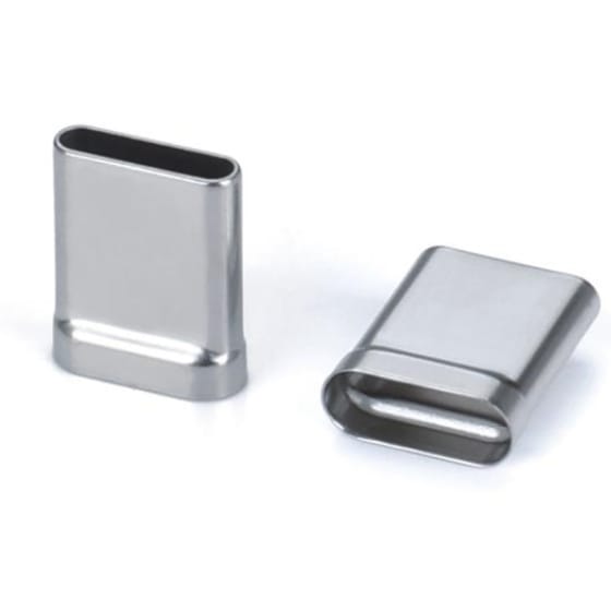
Leak-tight sensor housings and protective shells
Sensors often require stable geometry, controlled sealing surfaces, and protection from moisture or corrosion. Converting multi-piece housings into deep drawn shells can remove seams, reduce leak paths, and simplify gasket placement.
EV and battery-related enclosures
Battery systems push OEMs toward lightweight designs with robust protection. Deep drawn stamping can integrate stiffening features directly into shells, reducing the need for welded reinforcements and the assembly steps that come with them.
Medical and laboratory components
Medical devices and lab equipment benefit from smooth surfaces, repeatable geometry, and reduced contamination traps. Removing weld seams and reducing assembly steps can support both cleanliness goals and process validation needs.
Aerospace and high-reliability products
When quality requirements are high and inspection costs grow rapidly, reducing welds can be an economic decision as much as a technical one—especially when the part geometry can be formed repeatably in a controlled stamping route.
When deep drawn stamping is not the best solution

Ultra-low volume or rapidly changing designs
If the geometry changes frequently or volumes are very low, welding or machining can remain more flexible. Tooling investment is justified when the design is stable enough to amortize.
Designs that require extremely thick sections or heavy machining features
Deep drawn stamping is ideal for sheet-based shells. If you require thick walls, deep pockets with sharp internal corners, or heavy threaded bosses, you may need hybrid approaches (deep draw + inserts, or deep draw + secondary machining).
When the “real problem” is tolerancing, not welding
Sometimes teams add welds or brackets to compensate for unclear datums or unstable tolerances. In those cases, improving tolerancing strategy (for example with ASME Y14.5 GD&T practices) can remove unnecessary complexity even before changing the process. (ASME Y14.5 standard page)
Why OEM teams choose JUMAI TECH for deep drawn stamping programs
We focus on weld elimination as a DFMA outcome
At JUMAI TECH, we don’t treat deep drawn stamping as a standalone operation. We treat it as a DFMA tool to reduce:
- Weld seams
- Brackets and fasteners
- Manual alignment steps
- Inspection points and rework risk
We collaborate early to identify which joints can be designed out and which features should be formed into the part.
Integrated capabilities from tooling to production stability
Successful deep drawn stamping depends heavily on die design, process sequence, and long-term tool maintenance. Our team supports:
- DFM feedback to improve drawability and reduce risk
- Progressive and multi-stage tooling strategies
- Secondary operations planning (trim, pierce, form, coin)
- Program support for first-offs, sampling, and scaling
One supplier ecosystem for deep-drawn components, dies, and precision copper parts
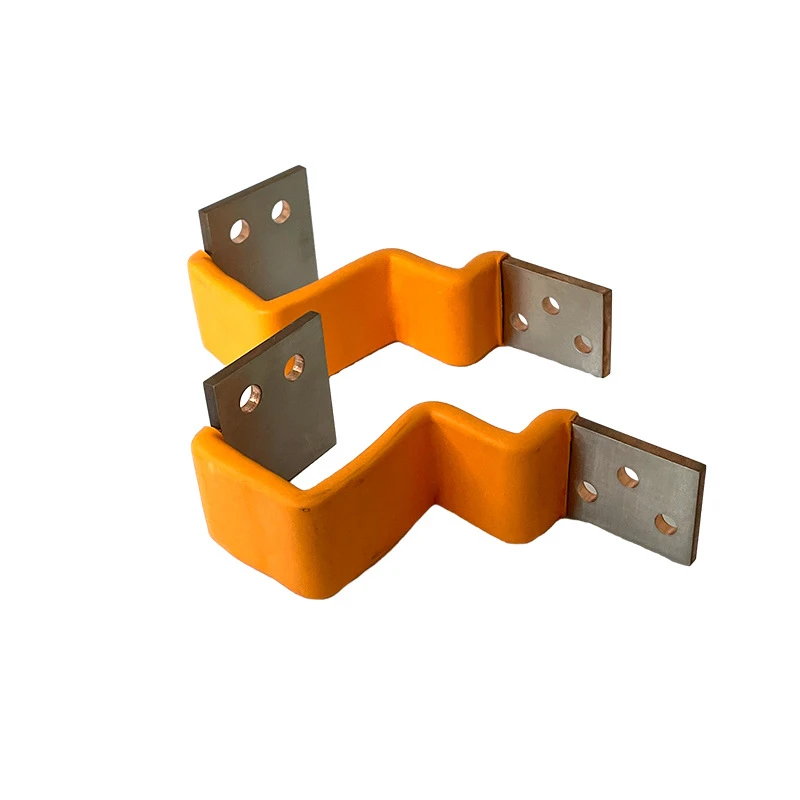
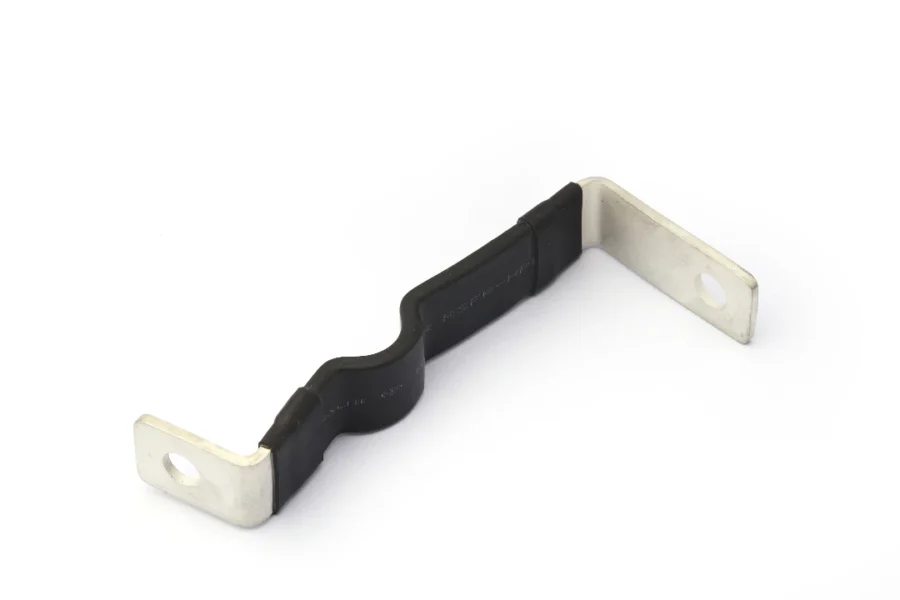
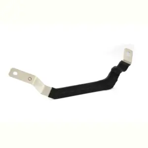
Because JUMAI TECH supports Deep-Drawn Components, Precision Stamping Dies, and Precision Copper Busbars, OEM teams can reduce supplier handoffs and keep critical manufacturing knowledge in one place—especially valuable when a product integrates formed housings, stamped features, and conductive components.
Next steps: how to evaluate weld and assembly reduction for your part
Send the current design and the “weld + assembly map”
To evaluate whether deep drawn stamping can reduce welds and assembly steps, provide:
- Current drawings (2D/3D)
- The weld locations (or weld symbols)
- The assembly routing (stations or main operations)
- Critical-to-function requirements (sealing, strength, datums)
We propose a conversion concept and cost model
A good conversion proposal should include:
- Which welds are eliminated and why
- Which features are integrated into the deep drawn shell
- What secondary operations remain
- How tolerances and datums will be controlled
- A comparison of total program cost drivers (not just piece price)
Build confidence with prototypes and controlled sampling
Deep drawn stamping is most powerful when it scales cleanly. We typically recommend a path that proves geometry, sealing, and assembly simplicity before full production release.