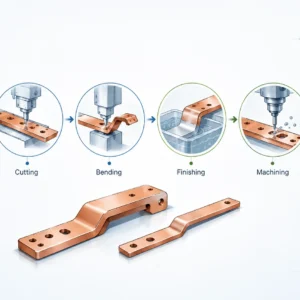
A stable stamping die process is not an accident—it’s the result of disciplined design choices that keep variation under control stroke after stroke. When the die runs “stable,” you get predictable dimensions, consistent burr height, fewer press stops, and a much longer window between sharpening and rebuilds. In this article, I’ll break down the key design rules that help OEM programs achieve repeatable output, whether you’re building a progressive tool for high volume or a transfer tool for complex forming.
Define “stable” before you design the stamping die

Stability means the process behaves the same way today, next week, and after 200,000 hits. Practically, you should be able to measure the output and see that variation stays predictable and centered, which is exactly what capability metrics like Cp/Cpk are meant to describe.
A stable stamping die process also shows stable uptime. That means fewer unplanned stops caused by misfeeds, slug pulling, galling, overload, or alignment drift, and less time “chasing” issues at the press.
Set measurable stability targets (not just “good parts”)
Before the stamping die design is finalized, define the targets that engineering, tooling, and production all agree on. Typical targets include scrap rate, allowed burr height, tool life between sharpenings, and process capability on critical-to-quality dimensions. These targets become your design constraints, not something you “inspect in” later.
Stability targets should be linked to how you will control the process on the floor. Statistical Process Control (SPC) uses repeated sampling and control charts to detect drift early, which is why many quality systems formalize its use.
Design for the real press environment
A stamping die that looks perfect in CAD can still be unstable if the press, feed system, lubrication, and coil variation aren’t considered. Stability requires forgiving design—features that self-locate, self-clear, and resist gradual wear without suddenly producing bad parts.
Lock the inputs: part print, material, and datums
The fastest way to create an unstable stamping die is to start tooling while inputs are still fuzzy. If the material spec, grain direction, coating, or datum strategy is unclear, the die will become the place where uncertainty turns into scrap and downtime.
A stable process starts with a controlled definition of what matters most: functional datums, GD&T on critical features, and realistic tolerances that match the stamping method. When designers align datums to how the part is actually held, piloted, and measured, the tool has a fair chance to run predictably.
Confirm material behavior early
Even “the same” alloy can behave differently by supplier, temper, coating, or thickness tolerance. Those differences change tonnage, springback, burr formation, and galling risk, all of which affect stamping die stability.
If you’re stamping copper or copper alloys for busbars, treat conductivity-focused alloys and high-strength variants differently. The more you control the incoming coil variability, the less you need to overcomplicate the tool.
Strip layout rules that prevent variation from the start
For progressive dies, strip layout is not just about material utilization. It controls how the strip moves, how it is piloted, and how forces balance, which directly drives stability.
A well-designed progression reduces side loads, avoids thin “weak bridges,” and gives pilots the best chance to correct feeder error. Strip layout is widely recognized as the core of progressive performance.
Put the pilot-hole creation in the right place
A common design rule is to create pilot holes early in the progression, so the strip can be accurately registered for the rest of the stations. Research on progressive die layout optimization explicitly notes that pilot-hole punches should be positioned in the first station under typical constraints.
This is not just theory—it’s how you protect the rest of the tool. When the strip is piloted early, downstream stations see less positional variation, which stabilizes both dimensions and tool wear.
Balance the cutting and forming forces
Unbalanced station forces can push the strip sideways, twist it, or load the guidance system unevenly. Over time, that creates progressive instability: guides wear faster, punches chip, and the process becomes “sensitive” to small changes in lubrication or coil camber.
A stable stamping die layout intentionally distributes high-load operations and uses pilots and guides to resist lateral movement. When you cannot fully balance forces, you compensate with better guidance, stronger backing, and robust strip control features.
Get punch–die clearance right (it’s the stability foundation)
Clearance is one of the most important—and most misunderstood—variables in a stamping die. If clearance is wrong, you will fight burrs, slug pulling, excessive tonnage, and rapid edge wear, and the process will never feel stable.
Many references discuss a “10% of stock thickness per side” rule of thumb for standard piercing, while also warning that it should not be blindly applied to every material and grade.
Use clearance as a design dial, not a fixed rule
A stable stamping die uses clearance to manage the tradeoff between edge quality, force, and tool life. Tighter clearance can reduce burrs and improve sheared edge appearance, but it increases stress and may reduce tool life; larger clearance can lower force and extend life, but may increase burr and rollover.
The key stability rule is simple: pick clearance based on the part requirement and the material behavior, then keep it consistent with good guidance and maintenance. If you treat clearance as “whatever we always use,” your process stability will depend on luck.
Don’t ignore the “10% rule” warning
Industry commentary specifically calls out the risk of using the same clearance rule for every metal type and grade. MetalForming Magazine. That warning matters because different materials fracture differently, and coatings can dramatically change galling and wear.
A stable stamping die program documents clearance decisions by feature type (pierce, blank, trim, shave) and by material family. That documentation makes future troubleshooting faster and prevents “silent drift” when replacement inserts are built.
Build guidance and alignment that stay true over time

Alignment drift is a slow stability killer. You may run fine in tryout, then slowly see burrs rise, dimensions wander, and punches break more often, all because guidance and alignment were not robust enough.
Guide pins/posts and bushings are fundamental components for aligning die shoes and maintaining the relationship between the upper and lower sections.
Choose the right guiding system for the speed and load
Ball-bearing guidance systems are often used to reduce friction and improve accuracy in higher-speed applications. Technical discussions describe preloaded ball-bearing components and their benefits for high-production environments.
The stability rule is to match guidance to reality. If the press runs fast, with off-center loading, or with tight clearances, don’t under-spec the die set guidance and expect stability.
Follow proven die-set standards where possible
Some OEM tooling standards explicitly require four guide pins with ball-bearing guides and even specify an offset post to prevent mis-assembly. adient.portal.covisint.com While your exact requirement depends on your program, the underlying idea is universal: repeatable alignment is non-negotiable for a stable stamping die process.
When alignment is controlled, clearance stays consistent, and so does fracture behavior. That is why guidance quality often shows up later as “mysterious” burr and wear problems.
Design stations to avoid overload and shock
Shock loads and overload events make a stamping die unstable, even if they don’t break anything immediately. Every shock event can create micro-chipping, loosen fasteners, mark the die set, and increase the chance of slug pulling.
That’s why stability-focused design treats tonnage and force distribution as first-class design inputs, not something left to the press operator.
Calculate tonnage with realistic assumptions
Multiple tooling references provide punching/press force formulas based on perimeter (or circumference), material thickness, and material shear resistance/strength.These formulas are not perfect, but they help you avoid underestimating load.
The stability rule: calculate station forces conservatively, include a safety margin, and then validate in tryout. A stable stamping die process is one where the press is not living near its limit every stroke.
Reduce peak load when you can
When the load is too high, you have options besides “buy a bigger press.” You can change operation sequencing, add shear angles where appropriate, split heavy cuts into multiple stations, or change edge strategy (for example, pre-pierce + trim) to reduce peak tonnage.
Even small load reductions can stabilize the process by reducing snap-through shock, which protects guidance, fasteners, and cutting edges over long runs.
Control strip registration with pilots and release timing
Feed accuracy alone is rarely enough for stable progressive stamping. Pilot pins exist because they correct small feeder errors and “zero” the strip before critical work occurs.
Multiple technical articles describe how pilot pins engage the strip before other tooling contacts, forcing the strip into precise alignment.
Make pilots do real work (not just “touch”)
A stable stamping die uses pilots that enter properly sized pilot holes and have correct timing so the strip can float into position. Progressive setup guidance emphasizes that feeder release timing must allow pilots to position the strip correctly.
If pilots don’t fully seat, you will see repeating dimensional errors that come and go depending on coil tension, lubrication, or feeder behavior. That is classic instability.
Add strip control features that prevent wandering
Pilots correct position, but you still need the strip to behave between stations. Side guides, lift control, and proper strip support reduce side load on pilots and keep registration stable.
When strip wandering is controlled, punches see less side load. That reduces chipping and helps the stamping die keep stable performance deeper into its maintenance cycle.
Engineer stripping, slug control, and part ejection for “no surprises.”
Many stamping problems are not about forming—they are about what happens to scrap and parts after the cut. If slugs pull, scrap hangs, or parts bounce back into the die, you get sudden stops and damage, which destroys stability.
A stable stamping die design assumes the press will run fast and uses positive control: reliable stripping, controlled slug drop, and predictable ejection. That way, the process doesn’t rely on “it usually falls out.”
Prevent slug pulling by design
Slug pulling often starts as a small issue and becomes worse as edges wear. It creates random stops, random marks, and random punch breakage, which is the definition of instability.
Design rules that help include proper clearance, sharp edges, adequate slug retention strategy, and controlled slug evacuation paths. When these are built into the tool, you reduce the number of variables operators must manage.
Design part exits like it’s a station
Part ejection is a process step, not an afterthought. A stable stamping die will guide the part out of the forming area and prevent re-entry, especially when parts are small, light, or springy.
If the part exit is unstable, you can get intermittent double-hits and damage that looks “random.” In reality, it is a predictable outcome of uncontrolled motion.
Choose die materials, heat treatment, and surface engineering for long stability

Tool steel choice is not only about hardness. It is about wear resistance, toughness, dimensional stability in heat treatment, and how predictable the tool remains as it wears.
Authoritative materials guidance (including ASM handbooks) discusses the selection of materials for press-forming dies and mentions common cold-work tool steels such as A2 and D2 in die applications.
Match the steel grade to the failure mode
A2 is often used as an “all-purpose” cold-work tool steel, balancing wear and toughness, while D2 is known for higher wear resistance but lower toughness. Key Metals: A stable stamping die chooses steel based on what will actually kill the tool first: chipping, abrasive wear, galling, or deformation.
If your die fails by chipping, chasing maximum wear resistance can backfire. If your die fails by abrasive wear, a tougher steel alone may not stabilize the process.
Use coatings and treatments strategically
Surface engineering can dramatically improve stability by reducing friction and wear. Recent research explores coating systems (for example, DLC-related approaches) to increase wear resistance in stamping/punching tool applications.
The stability rule is to treat coatings as part of a system. Coatings work best when paired with correct substrate hardness, good surface finish, and appropriate lubrication.
Reduce galling and friction: lubrication is a stability lever
Galling and adhesive wear cause unstable quality because friction changes during the run. A setup that looks stable at the first hour can become unstable after friction rises, heat builds, and material transfers to the tool.
Research on sheet metal forming and wear has specifically examined how lubricant selection affects galling behavior.
Design the tool to “like” lubrication
Lubrication is not only a fluid choice. It includes surface finish, contact pressure, draw radii, and sliding distance, all of which the stamping die controls.
A stable process reduces extreme contact pressure where possible and avoids rough transitions that scrape off lubricant films. That way, lubrication does its job consistently instead of failing suddenly.
Plan for heat and debris
As speed increases, so does temperature and debris movement. A stable stamping die considers how lubricant, fines, and slugs move so they don’t get trapped and create random scratches or binding.
When you manage heat and debris, you prevent the “mystery marks” that often trigger unstable scrap spikes.
Add die protection and sensing to stop instability before damage
A stable stamping die process is not just mechanical—it is monitored. Die protection sensors detect misfeeds, end-of-coil conditions, part ejection failures, and scrap presence so the press can stop before the die is damaged.
Commercial die protection systems are designed to monitor multiple sensors and detect faults quickly. This is one of the most direct ways to convert “random catastrophic downtime” into “controlled stops with quick troubleshooting.”
Monitor the events that create expensive instability
The most valuable monitoring points are the ones that prevent die crashes: misfeed, slug presence, part-out, stripper position, and transfer confirmation. Industry discussions describe how die protection sensors detect whether a part or scrap is present or absent and then signal the press control system to stop.
Stability improves because you stop problems while they are still small. You also protect your tooling investment and keep the process predictable.
Upgrade press controls when needed
Modern press control upgrades are often paired with increased use of electronic die protection and automation. MetalForming Magazine. Even if you keep the same press, better monitoring can make the overall stamping die process dramatically more stable.
Safety rules that also improve stability
Safety and stability are linked because unsafe setups often rely on manual intervention, inconsistent guarding choices, and risky clearing behaviors. In contrast, stable processes are designed to run with controlled access, predictable stops, and clear procedures.
OSHA regulations for mechanical power presses address guarding and point-of-operation protection requirements. OSHA ANSI B11 standards also provide a structured framework for machine guarding and risk assessment.
Build the tool for safe setup and maintenance
A stable stamping die is one that can be set up the same way every time. That includes clear shut height targets, robust alignment features, safe access for sensors, and consistent clamp locations.
When setup is repeatable and safe, you reduce human variation. That makes the output more stable because fewer “small differences” are introduced from shift to shift.
Validate the stamping die, like you plan to run it

Tryout stability is not proven at low speed with perfect material and constant supervision. It is proven when the tool runs at the intended speed, with realistic coil variation, for enough strokes to show wear trends.
A stable stamping die validation plan includes first-off dimensional confirmation, run-at-rate trials, burr monitoring, and a defined maintenance interval based on measured wear rather than guesswork.
Use capability thinking, not only inspection
If you only inspect parts at the end, you discover instability after it has already cost you time and scrap. Capability thinking means you monitor the process so you can detect drift and correct it early, which is the core logic behind SPC.
When you combine smart tooling design with process monitoring, stability becomes repeatable across programs—not just on one “lucky” tool.
Document die maintenance as part of the design
Maintenance isn’t a separate world. A stable stamping die is designed with maintainability: replaceable inserts, accessible fasteners, protected wear surfaces, and clear sharpening limits.
If a die is hard to maintain, maintenance gets delayed or done inconsistently. That creates quality variation that looks like “process instability,” but is really “maintenance instability.”
The most common stability killers (and how stable dies avoid them)
Unstable stamping is usually caused by a small set of repeat offenders. The good news is that these are predictable and stable stamping die designs that actively defend against them.
- A wrong clearance strategy causes a constant fight between burr, force, and tool life. Rule-of-thumb guidance exists, but stable programs choose clearance intentionally by material and requirement.
- Weak guidance lets the tool “move” over time until quality drifts. Strong die-set guidance and proven approaches reduce that drift.
- Uncontrolled strip registration creates repeating errors and random punch load. Proper pilot design and correct feeder release timing stabilize registration.
- Overload and shock silently damage edges and components. Conservative tonnage calculation and load reduction improve long-run stability.
- Galling and friction growth change forming behavior during the run. Lubricant selection and surface engineering reduce galling risk.
- No die protection turns minor issues into crashes. Sensor-based monitoring stops the press before expensive damage occurs.
Each of these issues can be designed out, or at least designed down. That’s what stability-focused die engineering is really about.
Why JUMAI TECH focuses on stability-first stamping die design
At JUMAI TECH, we treat the stamping die as a production system, not just a tool. Stable dies reduce the total cost of ownership: less scrap, fewer stops, longer intervals between maintenance, and faster troubleshooting when something changes.
If your program includes precision stamping dies, deep-drawn components, or copper busbar-related stamped parts, stability matters even more because small variation can affect fit, conductivity interfaces, sealing, or downstream assembly. A stable stamping die process protects your quality targets while keeping throughput predictable.
What to send us for a stability-focused quote
To engineer stability efficiently, we typically start with the essentials: part drawing (with datums and tolerances), material spec, target volume, press/feed constraints, and your critical quality characteristics. From there, we can recommend the right die concept, guidance strategy, clearance philosophy, sensing plan, and maintenance approach to keep your process stable over the life of the program.
If you want, I can also convert this article into a WordPress-ready layout (with short CTA blocks, internal link placeholders, and FAQ schema) while keeping the same stamping die keyword strategy.
FAQs: Stamping Die Stable Process Design Rules
What does “stability” mean in a stamping die process?
Why is punch-die clearance considered the foundation of process stability?
How does strip layout influence the stability of progressive dies?
What role do pilots and release timing play in maintaining process control?
What are the most common “stability killers” in metal stamping?
Wrong clearance strategies lead to burrs and shortened tool life.
Weak guidance systems that allow the tool to drift over time.
Uncontrolled strip registration is causing misfeeds.
Overload and shock, which silently damage die components.
Galling and friction, which change forming behavior during a run.
Lack of die protection sensors to stop the press before minor issues become major crashes.