When space is limited, power still has to move safely, efficiently, and repeatably. A flexible copper busbar link is often the simplest way to route high current through compact switchgear, inverters, UPS systems, EV battery packs, and power distribution cabinets—especially when rigid bars can’t meet the bend, vibration, or assembly-access constraints.
At JUMAI TECH (DeepDrawTech), we design and manufacture custom flexible copper busbar links that fit real-world envelopes: tight clearances, awkward mounting angles, thermal hotspots, and installers wearing gloves with torque tools. This guide explains how to design flexible links that stay cool, stay tight, and stay reliable—even when everything around them is cramped.
Table of Contents
Why tight spaces make busbar design harder than it looks
Current density becomes the hidden enemy
In a compact layout, designers often shorten the path and shrink the cross-section to “make it fit,” and that’s where overheating begins. Higher current density increases resistive heating, and the surrounding parts (plastic covers, CTs, cable ducts, fans) can block airflow, trapping heat exactly where bolted joints and insulation are most sensitive.
A good flexible copper busbar design starts by treating temperature rise as a constraint, not a side effect. Copper industry guidance commonly ties busbar energy efficiency and reliability to controlled temperature rise above ambient. Copper Development Association
Movement, tolerance stack-up, and assembly access are real constraints
Tight spaces also mean tighter tolerance stack-up across frames, insulators, and mounting studs. Even a 1–2 mm shift can turn a clean bend into a stress concentrator or make a wrench impossible to seat on the nut.
Finally, compact systems move more than you expect. Vibration, thermal expansion, door/cover flex, and short-circuit forces all create micro-motions that can loosen joints if your flexible link is designed like a “thin rigid bar with a bend.”
The cost of a “fits today” design is paid later
A flexible link that only fits in CAD can become a rework nightmare on the factory floor. The best designs fit the envelope with margin, include alignment features, and are easy to install correctly the first time.
What a flexible copper busbar is—and what it is not
Common flexible link constructions
A flexible copper busbar generally means one of these constructions, chosen by current level, bend needs, and fatigue expectations:
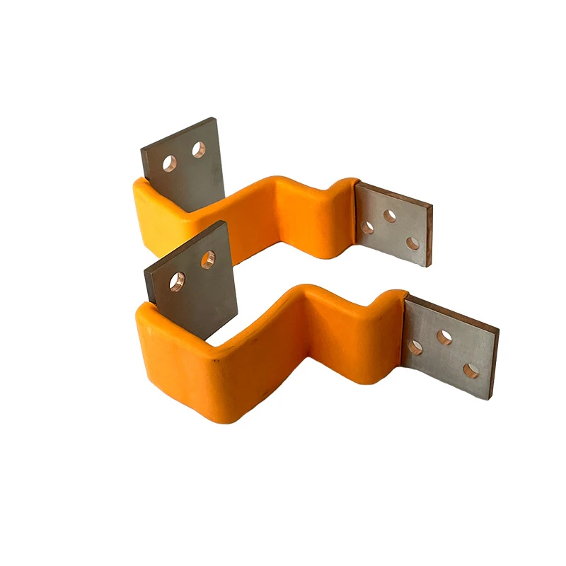
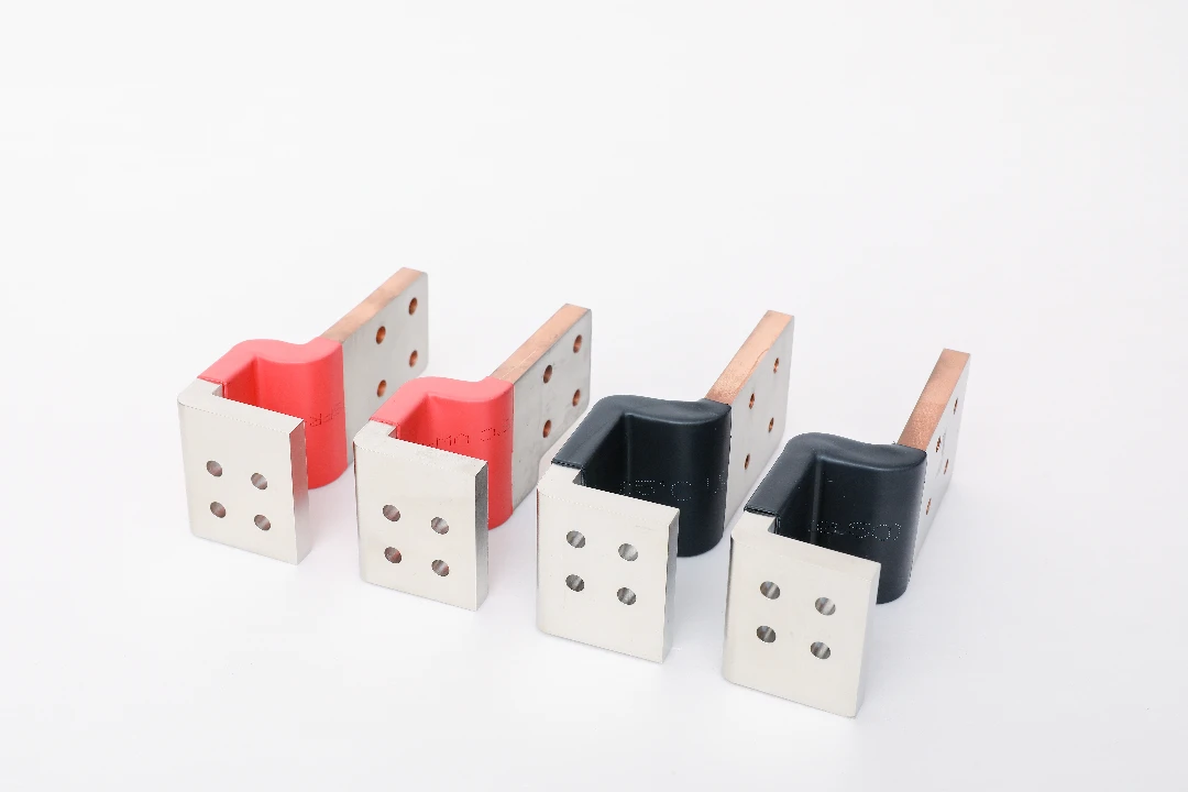
- Laminated flexible busbar (laminated shunt / laminated link)
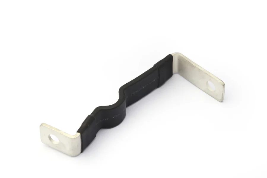
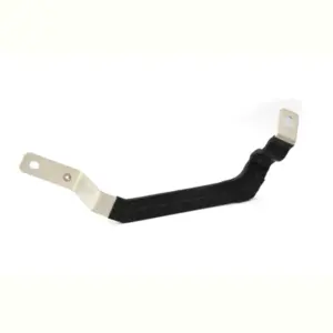
This uses multiple thin copper foils stacked together to create a low-inductance, highly flexible section with solid end-tabs for bolting. It is excellent for tight bends and repeated thermal cycling. - Braided copper flexible connector (copper braid strap)
Braids tolerate vibration well and are easy to route, but electrical performance and joint consistency depend heavily on termination quality and compression. - Cable-to-pad (high-strand cable crimped/welded to terminals)
This offers flexibility and routing freedom, but it usually has higher inductance than laminated links and requires careful termination control. - Expansion links / flexible joints
These are used to absorb thermal expansion in busbar runs and reduce mechanical stress transfer. Flexible joints are a known method for managing busbar thermal expansion in longer systems. electricalengineering-book.com
What “flexible” does NOT mean
A flexible link is not a substitute for proper electrical sizing, joint pressure, or thermal verification. If the end-tabs are undersized, or if contact surfaces are poorly prepared, flexibility won’t save you from hotspots, oxidation, or loosening.
Define the electrical requirements first (before you “shape it to fit”)
Rated current, duty cycle, and derating conditions
Start with the current profile and operating environment. A flexible copper busbar for a battery pack may see high peaks and moderate continuous current, while a switchgear feeder may see long-duration continuous current at elevated ambient.
Define these clearly:
- Continuous RMS current and maximum duration. Specify it in operating mode context, not as a single number.
- Peak current and peak duration. Peaks drive mechanical forces and transient heating.
- Ambient temperature and cooling method. Tight spaces often require derating because airflow is restricted.
IEC-based assembly verification commonly includes temperature-rise checks across busbars and connections, which is why your “design current” should be aligned with how the full assembly is verified in practice. Schneider Electric Blog
Voltage drop and resistance targets
In tight layouts, the path is short, but joint resistance can dominate. Set a target for mV drop across the link at rated current, and treat it as a quality metric for both design and production.
Also decide whether you want the flexible link to act as a “controlled resistor” for sensing or balancing. Most power links should minimize resistance, but some systems intentionally tolerate a small drop to simplify measurement.
Short-circuit and fault considerations
Even if a flexible link is short, it can see huge electrodynamic forces during faults. Your end-tabs, bolt pattern, and supports must keep the link from whipping into other phases or damaging insulation.
A practical rule is: if the surrounding system has meaningful short-circuit energy, the flexible link must be treated as a mechanical component, not just a conductor. That means defining support points, clearances, and restraint under worst-case events.
Translate “tight space” into a geometry model that manufacturing can hit

Build an envelope, not just a centerline
A centerline sketch is not enough. Create a 3D envelope that includes:
- Tool access zones for sockets and torque wrenches.
- Keep-out zones for sharp edges, fan housings, sensors, and covers.
- Minimum clearance to other conductors and grounded metal.
Then design the flexible copper busbar shape to stay inside that envelope with margin. This reduces the risk that the first prototype “fits only if you push it.”
Respect bend radius and neutral axis behavior
Every flexible construction has a practical minimum bend radius. Laminated foil sections bend cleanly, but they still need radius control to avoid foil edge damage and insulation cracking. Braids bend easily but can distort and creep if constantly stressed at the termination.
Design bends as controlled arcs, not hard corners. Controlled geometry improves repeatability and reduces fatigue in thermal cycling.
Tolerances and stack-up: design for assembly, not only for drawing
If two mating studs can vary by ±1 mm each, your link must tolerate the worst-case offset without twisting the termination. Including a short flexible “service loop” or a slightly longer foil section can dramatically increase yield and installation speed.
Choose the copper and surface finish intentionally
Copper grade and conductivity basics
For power links, you typically want high-conductivity copper with stable mechanical properties. Many buyers reference conductivity relative to %IACS, where annealed copper is defined as 100% IACS at 20°C (a widely used benchmark). NDE-ED
In North America and many global OEM supply chains, copper busbar material is commonly referenced to standards such as ASTM B187/B187M (bus bar, rod, and shapes). ASTM International | ASTM
Plating: tin, silver, nickel—why it matters in tight spaces
Plating is not “cosmetic.” In tight spaces, joints run hotter and see more moisture/contaminants trapped in stagnant air. Proper plating helps maintain stable contact resistance over time.
- Tin plating is widely used for corrosion resistance and good bolt-up consistency. It is often the practical default for industrial busbar joints.
- Silver plating can offer excellent conductivity and thermal performance at the interface, especially in high-current, high-temperature zones, but it must be specified carefully to match the mating hardware and environment.
- Nickel plating is used when you need a diffusion barrier or specific corrosion behavior, but it can increase interface resistance if not paired correctly.
Insulation and touch safety
In tight spaces, insulation must survive edge contact, thermal cycling, and installation abrasion. Depending on voltage and environment, common choices include:
- Heat-shrink tubing for simple protection and quick assembly.
- Laminated film insulation for controlled thickness and creepage.
- Coated or overmolded insulation for robust touch protection and abrasion resistance.
The correct choice depends on voltage class, creepage/clearance needs, and how the surrounding assembly is certified and verified.
Design the terminations like they are the product—because they are
Bolt pattern, hole sizing, and contact pressure
Most flexible copper busbar failures are not in the flexible section. They happen at the terminations due to poor contact pressure, wrong washers, uneven torque, or surface contamination.
Good termination design includes:
- Correct hole-to-edge distances to prevent tab cracking. This matters when tabs are thin to save space.
- Flatness control on the contact face. A “banana tab” creates micro-gaps that heat up.
- Hardware stack definition (washer type, spring elements, torque spec) so the joint behaves consistently.
Surface preparation and oxidation control
Even a high-quality plated surface can be compromised by fingerprints, cutting fluids, or packaging abrasion. In a tight assembly, rework is costly, so the design should encourage clean handling and robust mating.
If your system uses dissimilar metals (copper-to-aluminum, copper-to-tinned lugs, etc.), define the joint approach early. In some cases, the flexible link should include a bimetal interface strategy rather than relying on the installer to “solve it with paste.”
Joining methods: brazing, welding, diffusion bonding, riveting
For laminated flexible links, the way the foils are joined to the end-tabs is critical. The joining method affects resistance, heat spreading, and long-term stability under cycling.
At JUMAI TECH, we choose the joining method based on current, thickness stack, and the customer’s thermal margin. A slightly more robust joint can allow a smaller overall envelope—which is often the real goal in tight spaces.
Thermal design: keep the flexible copper busbar cool inside the box

Think in heat paths, not only ampacity tables
In cramped enclosures, the flexible link often runs near heat sources like IGBT modules, capacitors, or transformers. Your design should treat the flexible copper busbar as part of the thermal network.
Key tactics include:
- Increasing termination mass to act as a heat spreader. This can reduce hotspot temperature without changing the flexible section.
- Placing the flexible section away from radiant heat sources. Sometimes a 10 mm reroute provides a major thermal benefit.
- Avoiding insulation choices that trap heat when continuous current is high.
Control hotspots at the joints
Joint hotspots can exceed the flexible section temperature by a large margin. That’s why stable contact resistance and good surface quality matter so much.
If you’re designing for a certified assembly, temperature rise limits and verification methods should guide how much margin you need at the joints. IEC-oriented discussions of verification emphasize that busbars and connections must carry rated current without unacceptable hotspots. Schneider Electric Blog
Prototype with instrumentation in the real enclosure
A flexible link may pass open-air testing but fail in the final cabinet because the cabinet is the real thermal environment. Put thermocouples at:
- Each termination contact zone.
- The midpoint of the flexible section.
- Nearby heat sources that might couple into the link.
This is how you avoid the classic “the link is fine, but the joint is cooking” surprise.
Mechanical reliability in tight spaces: vibration, fatigue, and cycling
Manage strain at the transition zones
The most fatigue-sensitive region is usually where flexible material transitions into the rigid termination. Tight spaces can force sharp direction changes right at this boundary, which accelerates failure.
Design fixes include:
- Longer transition lengths so bending occurs in the intended flexible zone.
- Strain-relief geometry that encourages a smooth arc rather than a kink.
- Support or clamp features that prevent the link from vibrating freely.
Vibration behavior depends on construction
Braids naturally damp vibration, but terminations must be robust to prevent strand fretting. Laminated links handle repeated motion well if bend radius is respected and the joint to the tabs is properly designed.
If your application involves frequent service access (covers open/close, modules swapped), design the flexible copper busbar so it can move without being forced into new shapes each time.
Thermal cycling is a mechanical test too
As current flows, copper warms and expands, and the surrounding structure may expand differently. Over time, cycling can relax hardware and change contact pressure if the joint system is not designed with spring elements or stable torque strategy.
In tight assemblies, the joint “lives hot,” so designing it like a high-reliability mechanical interface is essential.
Inductance and EMI: the tight-space advantage you should use
Laminated links can reduce loop inductance
When conductors are arranged to minimize loop area, the system experiences lower inductive voltage spikes during switching events. Laminated flexible busbars are often used in power electronics for this reason, particularly in inverter and capacitor connections.
If you’re fighting overshoot or ringing, a flexible copper busbar link with intentional geometry can be part of the electrical solution, not only a packaging workaround.
Don’t create accidental antennas
In a tight layout, it is easy to route a flexible link near sensitive signal wiring. Keep high di/dt paths compact and separated from control harnesses, and avoid long parallel runs with signal cables.
If shielding is needed, solve it at the system level, but don’t ignore the fact that busbar geometry is a major EMI lever.
Insulation, clearances, and safety inside compact assemblies

Tight spaces require disciplined creepage and clearance planning
Compact designs often fail safety review because the busbar “fits,” but clearances do not. Insulation thickness alone doesn’t guarantee compliance if edges, bolt heads, or burrs reduce distance to grounded metal.
Design for:
- Rounded edges and controlled burr direction.
- Insulation that remains stable after heat cycling.
- Proper spacing around fasteners and corners, not only along straight runs.
Touch protection and service behavior
If the cabinet is serviceable, the flexible copper busbar should be protected against accidental contact. The right insulation choice can also reduce accidental shorting during maintenance, which is a major practical risk in dense systems.
A design that is safe to handle is also faster to assemble and easier to certify. That combination is often what OEMs actually want when they say “make it fit.”
Manufacturing a flexible copper busbar link: what matters for repeatability
Process flow that supports tight tolerances
A flexible copper busbar is deceptively simple in appearance, but consistent performance depends on repeatable manufacturing steps:
- Precision cutting or stamping for foils and tabs.
- Controlled stacking alignment for laminated sections.
- Stable joining method with low resistance and high mechanical integrity.
- Plating and surface protection that survive packaging and shipment.
- Insulation application that doesn’t introduce wrinkles, voids, or sharp edges.
For volume programs, tooling strategy matters. A progressive die approach can reduce cost and increase consistency, but only if the design has been optimized for that tooling path.
Prototype fast, then lock the “design intent”
In tight-space projects, prototypes are not just for electrical validation. They are also for assembly validation: wrench access, bend feasibility, clearance robustness, and cable routing interaction.
At JUMAI TECH, we encourage customers to treat the first iteration as an “assembly proof,” and the second iteration as a “manufacturing proof.” That approach reduces the risk of expensive late changes.
Quality checks that prevent hotspots and field failures
Dimensional inspection is necessary but not sufficient
Tight-space links can pass dimensional checks and still fail because of subtle resistance issues at terminations. That’s why we focus on electrical and interface quality, not only geometry.
Common verification steps include:
- Contact surface flatness and plating thickness checks. These support stable joint resistance over life.
- Millivolt drop or resistance measurement at defined current. This catches termination defects early.
- Visual and edge-quality inspections to prevent insulation damage and creepage problems.
Align your material and drawings with recognized references
When customers specify recognized material references, it reduces ambiguity and supports consistent supply. For example, ASTM B187/B187M is widely used to specify copper bus bar material in electrical applications. ASTM International | ASTM
For system-level validation, industry guidance and standards discussions around busbar temperature rise and design verification help frame what “good” looks like in an enclosure, not only on a bench. Copper Development Association
A practical RFQ checklist for flexible copper busbar links in tight spaces
What to send so we can quote accurately
Provide these items to avoid delays and redesign loops. Each one reduces risk in tight-space projects, where assumptions are expensive:
- Electrical requirements (continuous/peak current, duty cycle, voltage class, expected ambient). Include the enclosure cooling approach so we can size for real thermal conditions.
- Mechanical envelope (3D model preferred, or detailed 2D with keep-outs and tool-access zones). Include mating stud locations and tolerance expectations.
- Connection details (hardware stack, torque spec, mating material/plating). This lets us design the termination interface for stable contact resistance.
- Environmental conditions (vibration, corrosion risk, service cycles). These drive construction choice—laminated vs braid vs cable-to-pad.
- Compliance expectations (internal specs, customer standards, or assembly verification approach). This clarifies insulation and documentation needs.
What we can deliver from JUMAI TECH
We support custom flexible copper busbar programs from prototyping to volume, including:
- Laminated flexible copper busbar links with precision end-tabs.
- Braided copper connectors with controlled terminations.
- Custom plating and insulation options matched to your environment.
- DFM support to reduce cost while improving assembly robustness.
If you’re struggling with a cramped power path, the fastest win is often a flexible link that is intentionally designed for the envelope rather than forced into it after the fact.