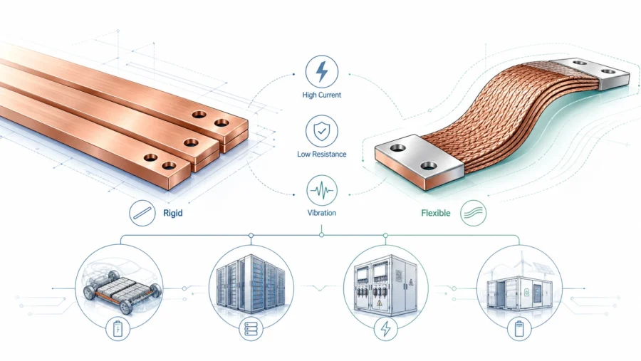
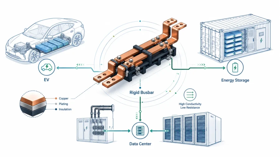
In the rapidly evolving landscape of power electronics—ranging from Electric Vehicle (EV) battery packs and renewable energy inverters to hyperscale data centers—the demand for higher current density is unrelenting. As engineers and manufacturers, we are pushing the boundaries of what electrical infrastructure can handle. At the heart of this infrastructure lies the rigid busbar, the critical backbone responsible for efficient power distribution. However, as current ratings climb into the thousands of amperes, one adversary remains constant: heat.
Thermal management is no longer an afterthought; it is a primary design constraint. Excessive heat in a rigid busbar system not only degrades the conductivity of the copper (increasing resistance and creating a thermal runaway loop) but also compromises surrounding components, melts insulation, and poses severe safety risks. At JUMAI TECH, where we specialize in Precision Copper Busbars and Deep-Drawn Components, we have observed that over 60% of busbar failures are directly linked to poor thermal management or improper joint design.
This guide serves as a definitive resource for engineers and procurement specialists. We will explore the physics of heat generation, the nuances of material selection, and the geometric optimizations necessary to ensure your rigid busbar systems operate efficiently, safely, and reliably over their lifespan.
Table of Contents
The Physics of Heat Generation in Rigid Busbars
To solve the thermal problem, we must first understand its source. Heat in a rigid busbar is primarily generated through Joule heating (also known as resistive heating). The fundamental formula governing this is P = I2R, where P is the power dissipated as heat, I is the current, and R is the resistance of the conductor.
Understanding Resistive Losses
While copper is an excellent conductor, it is not a superconductor. It possesses inherent internal resistance. As current flows, collisions between moving electrons and the atomic lattice generate thermal energy. In DC applications, this is straightforward. However, as the temperature of the busbar rises, the problem compounds. Copper has a positive temperature coefficient of resistance (approximately 0.00393 per °C). This means that as your rigid busbar gets hotter, its resistance increases, leading to even more heat generation—a potential runaway scenario if heat dissipation is not adequate.
The Impact of Skin and Proximity Effects
In AC applications, such as solar inverters or wind turbine converters, the physics becomes more complex due to the Skin Effect. As frequency increases, current density tends to concentrate near the surface of the conductor, leaving the center with little current flow.
- Skin Effect: Effectively reduces the cross-sectional area available for current flow, thereby increasing the effective AC resistance (Rac) compared to DC resistance (Rdc).
- Proximity Effect: When multiple busbars carrying alternating current are placed close together, their magnetic fields interact, causing further non-uniform current distribution and localized hot spots.
For high-frequency applications, simply increasing the thickness of a rigid busbar yields diminishing returns. Instead, increasing the surface area (width) becomes the superior strategy for both electrical efficiency and thermal dissipation.
Material Selection: The Foundation of Thermal Performance
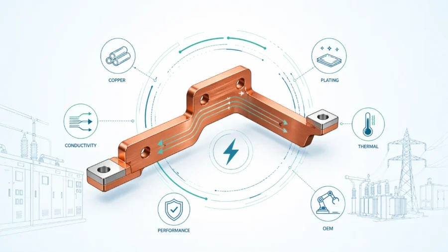
The choice of material is the first line of defense against thermal inefficiency. At JUMAI TECH, we strictly control the sourcing of our raw materials because impurities are the enemy of conductivity.
Copper vs. Aluminum Alloys
While aluminum is lighter and cheaper, copper remains the gold standard for high-power rigid busbar applications due to its superior thermal and electrical conductivity.
Comparative Data: Copper vs. Aluminum
| Property | Copper (C11000/ETP) | Aluminum (6101-T6) | Advantage |
| Electrical Conductivity (IACS) | 100% – 101% | ~57% | Copper allows smaller cross-sections for the same current. |
| Thermal Conductivity (W/m·K) | ~401 | ~218 | Copper dissipates heat away from hotspots nearly 2x faster. |
| Melting Point (°C) | 1085 | 660 | Copper offers higher safety margins during short circuits. |
| Thermal Expansion (µm/m·K) | 16.5 | 23.6 | Copper puts less stress on joints during thermal cycling. |
Oxygen-Free vs. ETP Copper
For standard applications, Electrolytic Tough Pitch (ETP) C11000 copper is the industry standard. However, for precision applications involving vacuum brazing or environments where hydrogen embrittlement is a concern, JUMAI TECH recommends Oxygen-Free Electronic (OFE) C10100 copper.
Using high-purity copper (99.99%) ensures that the theoretical resistance is minimized. A mere 0.1% increase in impurities can significantly drop conductivity ratings, leading to unnecessary heat generation before the system even powers up. For more on copper standards, you can refer to the Copper Development Association (CDA) resources.
Optimizing Busbar Geometry for Natural Convection
Once the material is selected, the physical shape of the rigid busbar dictates how effectively it can shed heat into the surrounding air. Heat dissipation occurs via three mechanisms: conduction, convection, and radiation. In most air-cooled systems, convection and radiation are dominant.
The Importance of Aspect Ratio
A common misconception is that cross-sectional area alone determines ampacity (current carrying capacity). In reality, the perimeter of the cross-section is equally vital.
Consider two busbars with the same cross-sectional area of 100mm²:
- Square Bar: 10mm x 10mm (Perimeter = 40mm)
- Rectangular Bar: 50mm x 2mm (Perimeter = 104mm)
The rectangular rigid busbar has over 2.5 times the surface area for the same amount of copper. This increased surface area allows for significantly higher convective cooling. At JUMAI TECH, we generally recommend a width-to-thickness ratio of at least 10:1 for systems relying on natural convection.
Orientation Matters
The installation orientation of the busbar significantly affects convective airflow.
- Vertical Orientation (Edge-up): This is the optimal position. As the air heats up near the busbar surface, it rises. A vertical orientation creates a “chimney effect” along the tall flat faces of the bar, accelerating airflow and cooling.
- Horizontal Orientation (Flat-face up): This is the least efficient. Heated air becomes trapped under the bar or stagnates on top, reducing the heat transfer coefficient by as much as 20-25%.
Enhancing Emissivity: Surface Treatments and Coatings
Radiation is often underestimated in thermal calculations, but for a rigid busbar, it can account for 25% to 40% of total heat dissipation, depending on the temperature delta.
The Problem with Shiny Copper
Polished, shiny copper has a very low emissivity coefficient ($\varepsilon$), typically around 0.03 to 0.05. This means it radiates very little heat. It effectively keeps the heat trapped inside the metal.
Utilizing Paints and Heat Shrink
To improve radiative cooling, the surface emissivity must be increased.
- Matte Black Paint: Applying a thin layer of non-conductive matte black paint can raise emissivity to $\sim$0.90. This drastically improves the busbar’s ability to radiate heat to cooler surroundings.
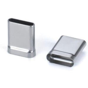
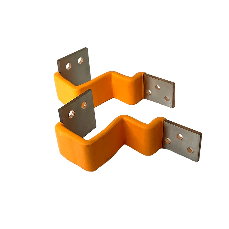
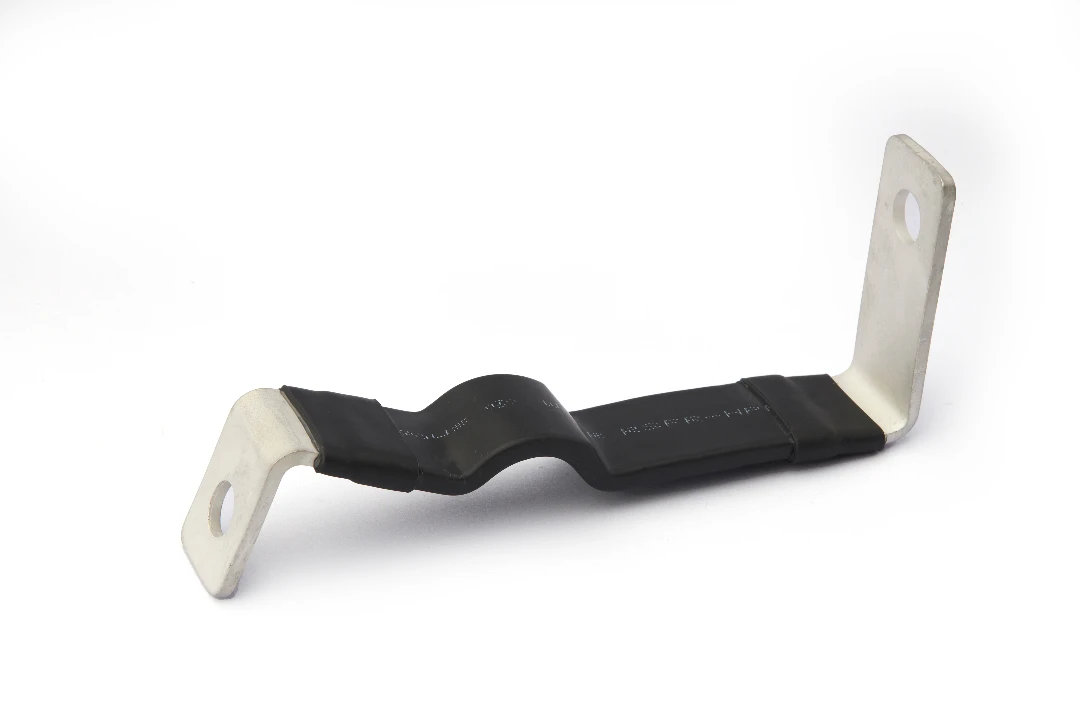
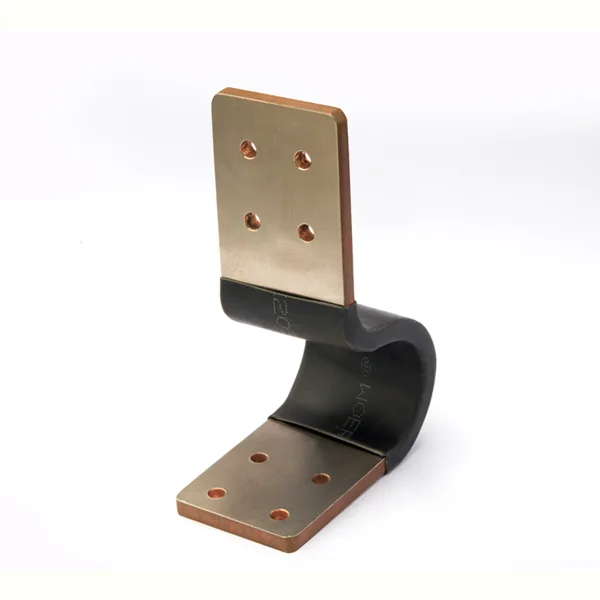
- Busbar Insulation Tubing (Heat Shrink): Surprisingly, adding electrical insulation can sometimes help with cooling. While the insulation material (like PVC or Polyolefin) adds a conductive thermal barrier, many black heat shrink materials have high surface emissivity ($\sim$0.95). For certain busbar geometries, the gain in radiative cooling outweighs the loss in conductive cooling through the insulation layer.
Table: Emissivity of Common Busbar Surfaces
| Surface Condition | Emissivity Coefficient (ε) | Thermal Performance Impact |
| Polished Copper | 0.03 | Very Poor |
| Oxidized Copper | 0.60 – 0.70 | Moderate |
| Aluminum (Anodized) | 0.80 | Good |
| Black Heat Shrink | 0.90 – 0.95 | Excellent |
| JUMAI TECH Special Coating | >0.95 | Superior |
Contact Resistance: The Hidden Heat Generator
Even the best-designed rigid busbar will fail if the connections are poor. The interface where two busbars meet (or where a busbar meets a terminal) is technically a discontinuity in the material.
Surface Roughness and Real Contact Area
Microscopically, two flat metal surfaces only touch at high spots known as “asperities.” The real area of contact is often less than 1% of the apparent overlap area. This constricts current flow, creating high localized resistance and significant heat.
JUMAI TECH’s Approach to Joint Optimization
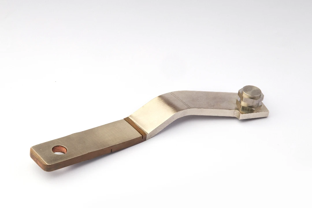
- Precision Stamping and Flattening: Using our Precision Stamping Dies, we ensure connection surfaces are impeccably flat to maximize contact area.
- Plating Selection:
- Tin Plating: Excellent for preventing oxidation and generally good for general industrial use. However, it is susceptible to fretting corrosion under vibration.
- Silver Plating: The premier choice for high-power, high-temperature applications. Silver oxide is conductive (unlike copper oxide), ensuring that even if the joint ages, thermal performance remains stable.
- Torque Control: Over-tightening bolts distorts the copper, reducing contact area. Under-tightening leaves air gaps. We provide specific torque specifications (Nm) based on bolt size and busbar hardness.
Advanced Cooling Architectures: Going Beyond Air
For ultra-high-power density applications, such as SiC (Silicon Carbide) based inverters or supercharging stations, natural convection is insufficient.
Laminated Busbars and Thermal Sinks
By utilizing our Deep-Drawn Components expertise, JUMAI TECH can integrate rigid busbar circuits directly with aluminum heat sinks. Using thin dielectric layers (like Kapton or Mylar) bonded between the copper and the heat sink allows for efficient heat transfer away from the conductor while maintaining electrical isolation.
Liquid Cooled Busbars
In extreme scenarios, hollow copper busbars or busbars brazed to fluid-carrying tubes are utilized. This allows coolant (water-glycol mix) to actively extract heat from the conductor. This technology is increasingly relevant in EV battery packs where maintaining a uniform temperature ($\pm$ 2°C) across all cells is critical for battery longevity.
Simulation and Validation Standards
How do we ensure a design will hold up? Theoretical calculations are only the first step. At JUMAI TECH, we rely on rigorous validation.
Computational Fluid Dynamics (CFD) & FEA
Before a single prototype is cut, we perform Electro-Thermal Finite Element Analysis (FEA). We simulate the rigid busbar under maximum load, analyzing current density distribution and thermal gradients. This highlights “hotspots” near sharp corners or bolt holes, allowing us to modify the geometry digitally.
Industry Standards
Our designs are validated against international standards to ensure safety and compliance:
- DIN 43671: The standard for continuous current-carrying capacity of busbars.
- UL 891: Standard for Switchboards.
- IEC 61439: Low-voltage switchgear and controlgear assemblies.
Compliance with these standards ensures that the temperature rise of the busbar terminals does not exceed safe limits (typically max 105°C for standard insulation classes) above ambient temperature.
Case Studies: Thermal Solutions in Action
Application 1: Renewable Energy Storage System (BESS)
- Challenge: A client required a 2000A main DC bus system for a containerized battery storage unit. The ambient temperature inside the container could reach 50°C.
- Solution: JUMAI TECH replaced the proposed standard flat bars with a custom-engineered, vertically oriented, black-powder-coated rigid busbar array. We switched from C11000 to silver-plated joints to minimize contact resistance at the battery terminals.
- Result: The operating temperature dropped by 18°C compared to the initial design, significantly extending the life of the adjacent battery management system (BMS) electronics.
Application 2: EV Fast Charging Station
- Challenge: High heat generation in the tight confines of a 350kW charging dispenser.
- Solution: We developed a hybrid system that integrates deep-drawn copper elements with a liquid-cooled plate.
- Result: The system maintained stable conductivity even under peak-load cycling, enabling faster charging times for end users without thermal throttling.
Conclusion and Future Outlook
Thermal management of rigid busbar systems is a multidisciplinary challenge involving materials science, physics, and mechanical engineering. As power densities continue to rise, the “set it and forget it” approach to busbar design is obsolete. Every degree of temperature rise represents lost energy, reduced reliability, and potential safety hazards.
By optimizing geometry, leveraging high-emissivity surface treatments, ensuring joint integrity, and selecting the appropriate copper grade, manufacturers can achieve significant performance gains.
At JUMAI TECH, we do not just manufacture parts; we engineer solutions. With our integrated capabilities in Precision Copper Busbars, Deep-Drawn Components, and Stamping Dies, we are uniquely positioned to help you solve your toughest thermal challenges. Whether you are designing the next generation of electric vehicles or upgrading industrial switchgear, our team is ready to assist.
Ready to optimize your power distribution system?
Contact the engineering team at www.deepdrawtech.com today. Let us help you design a Rigid Busbar solution that runs cooler, lasts longer, and performs better.
FAQ
Why is thermal management critical in rigid busbar design?
Thermal management is vital because excessive heat increases the electrical resistance of copper, creating a “thermal runaway loop” where higher resistance generates even more heat. Poor thermal control can lead to insulation melting, degradation of surrounding components, and over 60% of busbar system failures.
How does the geometry of a busbar affect its cooling efficiency?
The surface area-to-volume ratio is key. For example, a thin, wide rectangular busbar (e.g., 50mm x 2mm) has much more surface area for convective cooling than a square bar (e.g., 10mm x 10mm) with the same cross-sectional area. The article recommends a width-to-thickness ratio of at least 10:1 for optimal natural convection.
Does painting or insulating a busbar always make it hotter?
Not necessarily. While insulation creates a thermal barrier, many matte black paints or heat-shrink materials have high emissivity (up to 0.95). Since shiny copper has very low emissivity (0.03–0.05), adding a high-emissivity coating can actually improve the busbar’s ability to radiate heat, often outweighing the loss in conductive cooling.
What is the best orientation for installing rigid busbars to ensure cooling?
Vertical orientation (edge-up) is the most efficient. This position creates a “chimney effect” where heated air rises quickly along the tall flat faces of the bar. Horizontal orientation is the least efficient because heated air can become trapped or stagnate around the surface, reducing cooling efficiency by 20-25%.
Why is contact resistance considered a “hidden heat generator”?
On a microscopic level, two metal surfaces only touch at high spots (asperities), meaning the actual contact area is often less than 1% of the total overlap. This constriction increases resistance and creates localized hotspots. Using silver plating and precise torque control is recommended to maintain stable conductivity and minimize heat at joints.