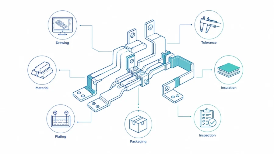
Rigid Busbars are not simply pieces of copper cut into convenient shapes. In modern electrical equipment, they are engineered current paths that must carry high current, control temperature rise, fit within tight mechanical envelopes, maintain stable contact resistance, and survive years of thermal cycling, vibration, installation stress, and maintenance handling. A small error in hole position, burr height, bend angle, plating coverage, insulation window, or packaging protection can become a real problem when the busbar is assembled into a switchgear cabinet, battery energy storage system, EV power unit, data center power distribution module, inverter cabinet, or industrial power conversion system.
For buyers, understanding the manufacturing process is therefore a commercial advantage. It helps purchasing teams compare suppliers beyond the unit price. It helps engineers prepare better drawings and RFQ information. It also reduces the risk of sample delays, assembly interference, unexpected temperature rise, poor contact surfaces, and production inconsistency. A good rigid busbar supplier should be able to explain not only what material will be used, but also how the copper will be cut, punched, formed, deburred, cleaned, plated, insulated, inspected, packed, and documented.
At JUMAI, rigid copper busbar manufacturing is treated as a combined electrical, mechanical, and process-control project. JUMAI manufactures custom flexible, rigid, and braided copper busbars, and also supports related deep-drawn and precision stamped components. That is important because a real busbar project rarely exists alone. It may need brackets, protective covers, terminal plates, insulation windows, spacers, positioning features, or stamped accessories. For a broader view of JUMAI’s copper busbar capability, buyers can also review the custom precision copper busbars guide, the article on advanced manufacturing for high-ampacity precision copper busbars, and the guide to rigid busbar design for compact cabinets.
This article explains the full Rigid Busbars manufacturing process in practical business language. It follows the journey from copper material selection to precision finishing and final inspection. It also includes tables, data references, and buyer-focused checklists that can be used during RFQ preparation, supplier evaluation, and design-for-manufacturing review.
Table of Contents
Why the manufacturing process matters to buyers
A rigid busbar is both a conductor and a structural component. It must conduct current efficiently, but it also has to align with breakers, contactors, battery modules, fuse holders, terminal blocks, laminated busbar stacks, insulation supports, and enclosure mounting points. Unlike flexible cable, a rigid busbar cannot easily compensate for design errors during assembly. If the bend angle is wrong, the hole center is off, or the terminal pad is warped after plating, the installer may be forced to rework the part, add stress to the joint, enlarge the hole, change the bolt stack, or delay the entire production line.
The manufacturing process also affects electrical performance. Copper has excellent conductivity, but the finished busbar performance depends on the whole current path. Burrs can damage insulation. Poor flatness can reduce contact area. Oxide or contamination can increase contact resistance. Uneven plating can create corrosion or solderability problems. Excessive forming stress can distort terminal pads. In high-current systems, these small process details are not cosmetic; they can change the thermal behavior of the assembly.
From a procurement perspective, a transparent process reduces hidden cost. A quote that only states copper grade, thickness, width, and unit price may look attractive, but it does not answer the questions that matter in production: How will hole tolerance be controlled? Is the bend radius realistic for the copper temper? Will plating occur before or after forming? How will insulation windows be masked? What inspection data will be shipped with the lot? How will parts be packed to prevent scratches and terminal deformation? A strong supplier gives answers before the sample order starts.
The following table summarizes the manufacturing roadmap and the buyer risk connected with each stage.
| Manufacturing stage | Main purpose | Typical buyer risk if ignored | What buyers should confirm |
|---|---|---|---|
| Material selection | Match conductivity, forming, strength, and cost | Wrong copper grade, poor bendability, unclear certificate | Copper grade, temper, standard, conductivity, certificate type |
| Engineering review | Convert electrical and mechanical needs into manufacturable geometry | Over-designed copper mass, impossible bend, unclear insulation window | Current, voltage, temperature rise, drawing, terminal stack, enclosure limits |
| Cutting and blanking | Create repeatable copper blanks | Poor edge quality, dimensional drift, wasted material | Cutting method, tolerance, nesting, edge condition |
| Punching and drilling | Create mounting holes, slots, cutouts, and clearance features | Misaligned holes, burrs, joint stress, assembly rework | Hole tolerance, burr control, countersink/counterbore needs |
| Bending and forming | Route the busbar through the assembly space | Wrong angle, cracking, springback, inconsistent fit | Bend radius, grain direction, tooling, angle tolerance |
| Deburring and edge finishing | Remove sharp edges and protect insulation/users | Cut insulation, operator injury, partial discharge risk | Deburring method, edge radius target, visual criteria |
| Cleaning and surface preparation | Remove oil, oxide, debris, and processing residues | Poor plating adhesion, unstable contact resistance | Cleaning route, drying, handling protection |
| Plating or surface treatment | Improve contact reliability, corrosion resistance, or solderability | Poor contact surface, tarnish, inconsistent thickness | Tin/silver/nickel plan, thickness, masking, standard reference |
| Insulation or coating | Provide electrical separation and touch protection | Wrong window location, coating voids, poor adhesion | Material, thickness, dielectric test, window tolerance |
| Final inspection | Verify dimensions, surface, conductivity, and documentation | Batch inconsistency, assembly failure, quality dispute | CMM/check fixture, plating thickness, resistance, report format |
| Packaging | Protect finished geometry and contact surfaces | Scratches, bent terminals, mixed parts, lost traceability | Individual separation, labels, moisture control, batch identification |
Understanding Rigid Busbars as engineered components
Rigid Busbars are solid conductive bars, plates, or formed copper conductors used to distribute power inside electrical equipment. They may look simple compared with cables, but their performance depends on geometry, surface condition, joint design, thermal environment, and assembly discipline. A rigid busbar may be a flat rectangular strip, a multi-bend three-dimensional conductor, a punched and plated terminal plate, a busbar with threaded inserts, a busbar with an insulated body and exposed connection windows, or part of a larger current-distribution assembly.
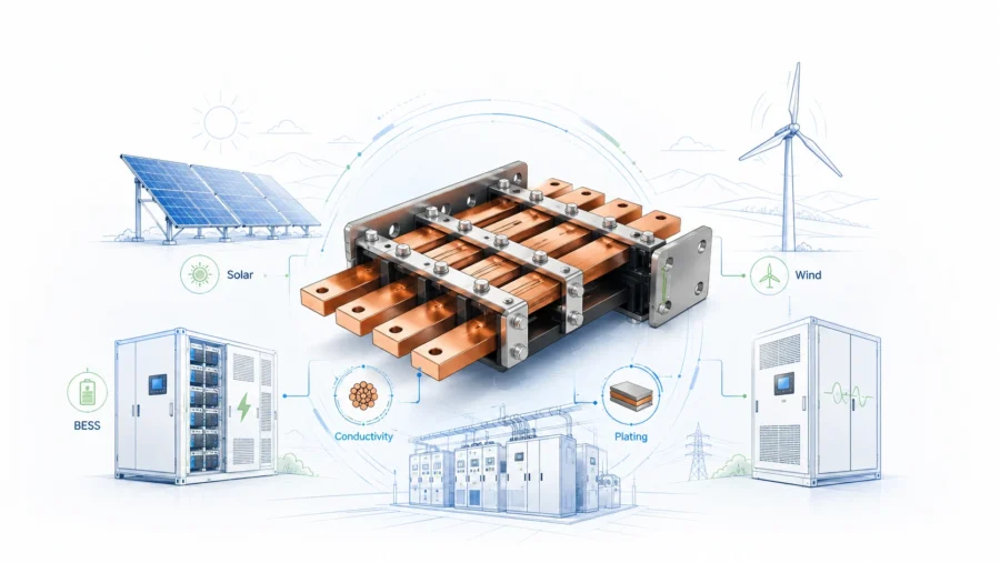
Common application areas include low-voltage switchgear, industrial control cabinets, data center power distribution, EV battery and inverter systems, solar and energy storage equipment, charging infrastructure, UPS systems, welding equipment, marine power systems, railway power modules, and heavy machinery. In many of these systems, the busbar must carry hundreds or thousands of amperes while still fitting inside a compact cabinet. JUMAI’s article on rigid busbar systems explains why engineering teams often choose rigid busbars for repeatable routing, clean installation, stable current paths, and lower long-term assembly risk.
A key point for buyers is that current rating cannot be judged from cross-sectional area alone. The final current-carrying capacity depends on material conductivity, surface area, orientation, number of bars, spacing, enclosure ventilation, ambient temperature, allowable temperature rise, coating emissivity, AC or DC conditions, proximity effect, connection resistance, and the heat contribution from adjacent components. The Copper Development Association’s DC copper busbar ampacity tables state that their ratings are based on a 30°C rise above a 40°C ambient and include assumptions about bar orientation and spacing. This is why a supplier should never quote a critical busbar only from width and thickness without asking about installation conditions.
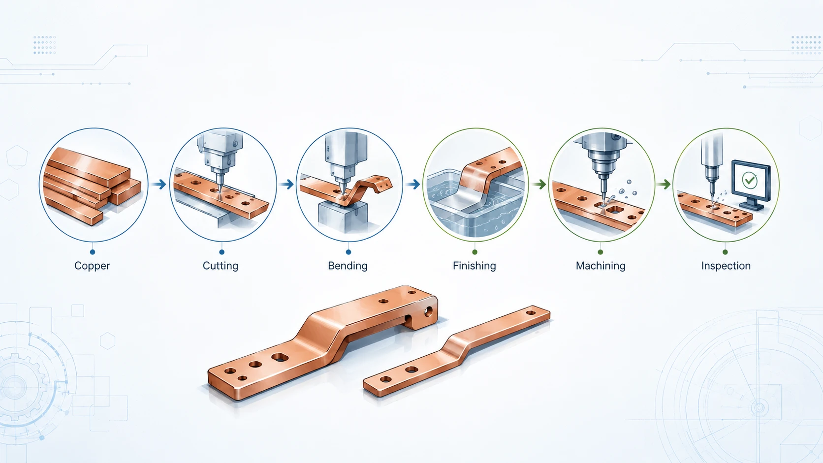
Rigid busbar manufacturing is therefore a translation process. The buyer starts with electrical and mechanical requirements. The supplier converts those requirements into a manufacturable copper geometry. The process then controls each manufacturing step so that the finished part matches both the drawing and the functional intent.
Material selection: the foundation of conductivity and manufacturability
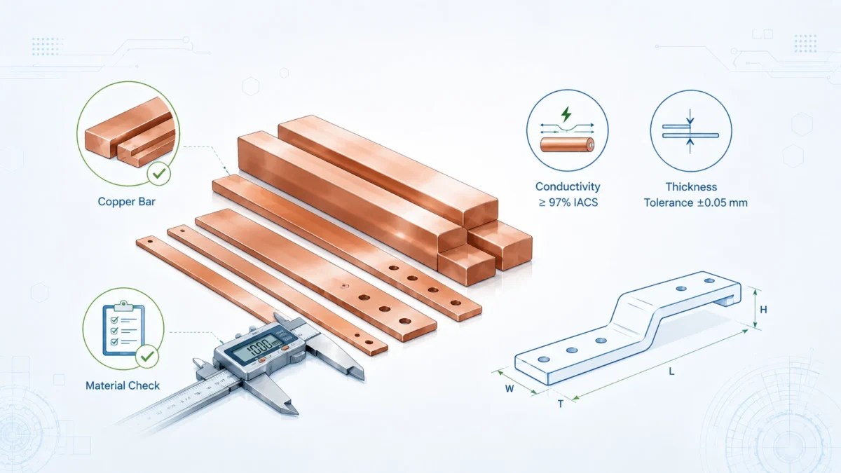
The first major decision is copper material. In most electrical busbar applications, buyers specify high-conductivity copper such as C11000 electrolytic tough pitch copper, oxygen-free copper grades such as C10100 or C10200, or regional equivalents such as T2 copper. The exact grade should be selected according to conductivity, forming needs, hydrogen embrittlement concerns, plating requirements, cost, and availability. The material should also be matched to the drawing’s bend radius and mechanical stiffness requirements.
ASTM B187/B187M is a key reference because it covers copper bus bar, rod, bar, and shapes for electrical and general applications. The ASTM overview for B187/B187M states that the specification establishes requirements for copper conductor bars, rods, and shapes, including sampling and testing for dimensional, mechanical, electrical resistivity, and chemical composition requirements. For many international projects, buyers may not explicitly require ASTM documentation, but ASTM B187/B187M remains a useful reference point when defining copper busbar quality expectations.
The Copper Development Association also identifies ETP-110 copper as 100% IACS conductivity in its busbar ampacity information. IACS means International Annealed Copper Standard, a common reference for electrical conductivity. In simple buyer language, higher IACS means lower electrical resistance for a given size, which helps reduce heat generation. However, conductivity is not the only consideration. A copper temper that is too hard may resist deformation but be more difficult to bend tightly. A temper that is too soft may form easily but be less dimensionally stable during handling.
| Copper material or equivalent | Typical conductivity reference | Main manufacturing advantage | Common rigid busbar use | Buyer note |
|---|---|---|---|---|
| C11000 / ETP copper | About 100% IACS | Strong availability, excellent conductivity, common electrical grade | Switchgear, power distribution, industrial cabinets, data centers | Often the default choice for cost-effective high-conductivity rigid busbars |
| C10100 / OFE copper | Often above 100% IACS depending on specification | Very high purity, low oxygen, good for demanding electrical or vacuum-related needs | High-end electrical connections, specialized power electronics | Usually higher cost; specify only when the application truly needs it |
| C10200 / OF copper | High conductivity with low oxygen | Good balance of purity and processability | Electrical connectors, terminals, busbars requiring oxygen-free material | Useful when oxygen content or hydrogen embrittlement is a concern |
| T2 copper / regional equivalent | Common industrial high-conductivity copper | Widely used in Asian manufacturing supply chains | Custom rigid busbars, terminal plates, formed copper conductors | Confirm equivalence, chemistry, conductivity, and certificate format for export projects |
| Copper alloy grades | Lower than pure copper depending on alloy | Higher mechanical strength or spring characteristics | Special terminals, clips, contact supports | Not normally selected for main high-current busbar paths unless strength dominates |
Incoming material control should include more than a supplier name. A professional rigid busbar manufacturer should verify material thickness, width, surface condition, flatness, certificate information, and traceability before cutting starts. For high-current or safety-critical applications, buyers can request material certificates that identify grade, temper, conductivity or resistivity, chemical composition, lot number, and applicable standard.
Material thickness is also a commercial decision. More copper can reduce resistance and temperature rise, but copper is a major cost driver. Over-specifying thickness can make the busbar expensive, heavy, harder to bend, and harder to package. Under-specifying thickness can create overheating risk or mechanical weakness. A good engineering review balances ampacity, temperature rise, available space, terminal area, stiffness, and cost.
Engineering review and DFM before production
Before copper is cut, the supplier should review the design for manufacturability. This step is often where the biggest savings are found. A buyer may send a 3D model or a 2D drawing that appears complete, but manufacturing questions remain: Are the bend radii practical? Are holes too close to the bend line? Is the exposed copper window large enough for the terminal stack? Is there enough clearance from grounded metal? Is plating required on all surfaces or only on connection pads? Can the part be nested efficiently on copper sheet? Is the part too long to plate without special fixturing? Will the final busbar fit inside the packaging carton without bending damage?
For electrical design, the supplier should understand current, voltage, frequency, duty cycle, ambient temperature, enclosure ventilation, allowable temperature rise, short-time withstand requirement, terminal hardware, and insulation requirement. For mechanical design, the supplier should understand total length, bend angles, bend sequence, hole pattern, flatness requirement, torque area, stack-up tolerance, and final assembly position. For commercial planning, the supplier should understand annual quantity, prototype quantity, validation schedule, target cost, certification needs, and whether PPAP-style documentation is required.
JUMAI’s article on rigid busbar design for compact cabinets is especially relevant here because compact cabinets leave little room for assembly error. A busbar that is electrically sufficient may still fail commercially if it cannot be installed quickly, if it blocks maintenance access, or if it conflicts with cooling paths.
| DFM review item | Why it matters | Practical guidance for buyers |
|---|---|---|
| Bend radius | Tight bends can crack copper, distort plating, or create dimensional variation | Define minimum inside radius and confirm it is realistic for thickness and temper |
| Hole-to-bend distance | Holes near bends may deform during forming | Keep holes away from bend zones when possible or review sequence with supplier |
| Terminal pad flatness | Poor flatness reduces real contact area and increases resistance | Define flatness or use a controlled terminal pad area requirement |
| Edge condition | Sharp edges can cut insulation or increase handling risk | Specify deburred edges or edge radius where insulation is applied |
| Plating area | Full plating costs more and may complicate masking | Decide whether full-body plating or selective plating is needed |
| Insulation window | Misplaced windows can reduce creepage or expose copper | Provide exact window dimensions and tolerance from functional datums |
| Part identification | Similar busbars can be confused during assembly | Add part number marking, orientation marking, or color coding if needed |
| Packaging orientation | Formed busbars can be damaged during transport | Request trays, separators, foam, or dedicated cartons for critical shapes |
A useful DFM conversation does not weaken the buyer’s design intent. It protects it. Sometimes a small change in bend location, hole type, slot shape, edge radius, or plating window can reduce cost and risk without affecting electrical function. This is where an experienced manufacturer adds value that a commodity copper cutter cannot provide.
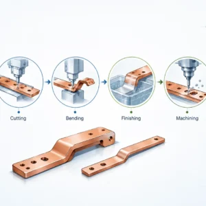
Cutting and blanking: converting copper stock into controlled blanks
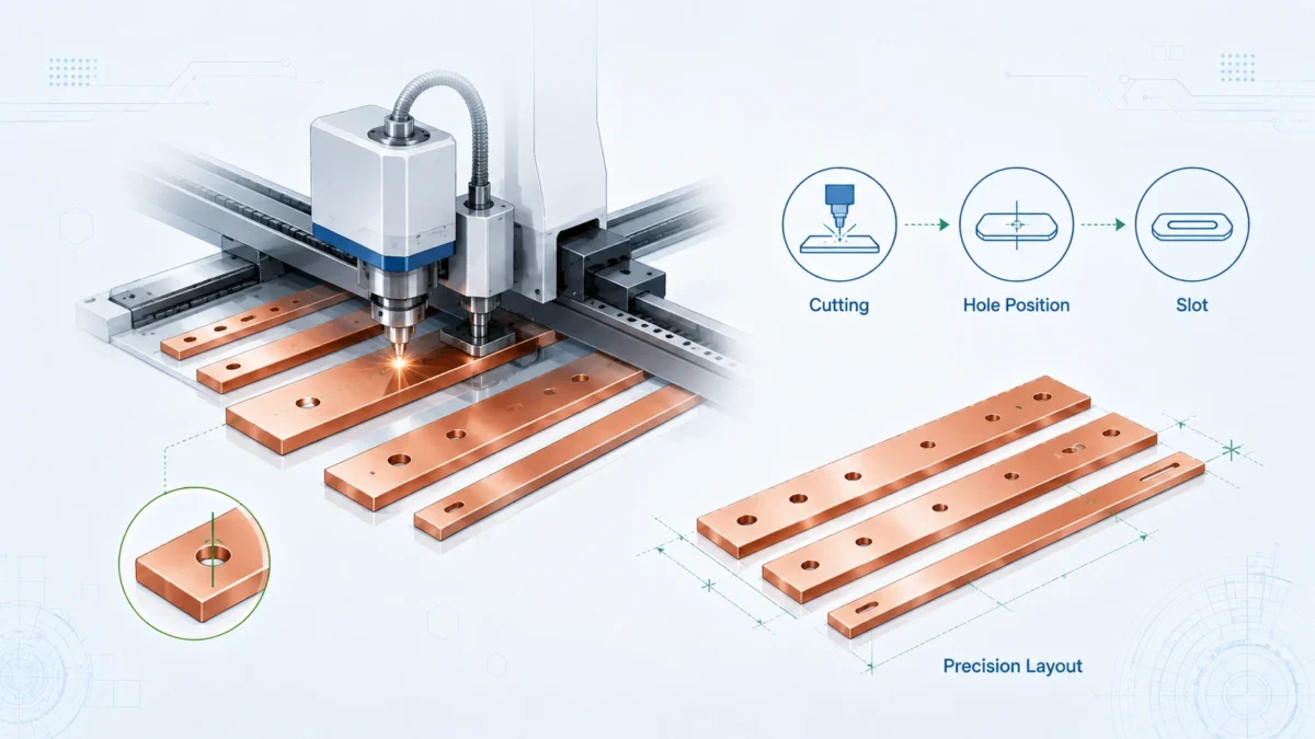
After the design is confirmed, the first physical manufacturing step is cutting or blanking the copper material. Depending on geometry, quantity, thickness, tolerance, and edge requirement, the supplier may use shearing, CNC punching, stamping, laser cutting, waterjet cutting, sawing, milling, or a progressive die. For low-volume prototypes, flexible cutting methods may be practical. For repeat production, stamping or dedicated tooling can reduce unit cost and improve consistency.
Shearing is efficient for simple rectangular blanks, but it can create edge deformation or burrs that must be controlled. CNC punching is suitable for repeated holes, slots, and simple contours. Laser cutting offers flexibility for complex outlines but requires attention to heat-affected edge quality and oxide removal. Waterjet cutting avoids thermal effects but may have slower cycle time and requires drying and cleaning. Milling is used when high precision, special profiles, or controlled slots are required, but it is usually slower and more costly.
The cutting process must be selected with the final function in mind. A busbar that will receive heat-shrink insulation may need smoother edges than a bare internal busbar. A busbar that will be plated may need surface preparation that removes cutting residue. A busbar with a tight fit in a molded holder may need tighter width tolerance than a simple cabinet conductor. For high-volume projects, the supplier should also consider material utilization. Efficient nesting can reduce copper scrap and therefore reduce total cost.
| Cutting method | Best suited for | Strength | Limitation | Buyer question |
|---|---|---|---|---|
| Shearing | Straight rectangular blanks | Fast, economical | Edge burr and slight distortion possible | How will the edge be deburred and measured? |
| CNC punching | Holes, slots, repeated features | Productive and repeatable | Tooling marks and burr direction must be controlled | Are hole positions referenced from functional datums? |
| Laser cutting | Complex contours, prototypes | Flexible and accurate | Edge oxide and heat effects may require cleaning | Will the edge be cleaned before plating or insulation? |
| Waterjet cutting | Thick copper or heat-sensitive profiles | No thermal edge | Slower, possible taper, drying required | Is taper acceptable for the mating feature? |
| Stamping die | High-volume repeat production | Low unit cost, stable repeatability | Tooling cost and lead time | At what volume does tooling become economical? |
| CNC milling | High-precision pockets or profiles | Excellent control | Higher cost, slower | Which features truly need milled precision? |
A strong supplier should document the selected route and identify which dimensions are process-critical. For example, the outside profile may be less critical than hole center distance, terminal pad location, bend line position, or insulation window location. Buyers should avoid applying very tight tolerance to every dimension unless necessary, because unnecessary tolerances increase cost without improving function.
Punching, drilling, slots, and connection features
Connection points are where many busbar problems begin. The main conductor may be sized correctly, but if the hole pattern is wrong, the bolt stack is unstable, or the terminal surface is poor, the joint can generate heat. For rigid busbars, holes and slots are not only mechanical features; they are part of the electrical contact system.
Holes can be punched, drilled, reamed, countersunk, counterbored, tapped, or machined depending on the design. Punched holes are efficient and common, especially for copper sheet and bar. Drilled or reamed holes may be used for tighter tolerance or thicker sections. Slots allow assembly adjustment, but they can also reduce contact area or change current distribution if placed poorly. Countersunk or counterbored features help reduce protrusion in compact assemblies, but they must leave enough copper thickness and mechanical strength.
Burr direction matters. If a punched burr is on the contact side, it can prevent the terminal pad from seating flat. If the burr is on an insulation side, it can cut coating or heat-shrink material. The supplier should define whether holes are deburred on both sides, whether countersinks are used for burr removal, and whether terminal pads are flattened after forming.
Threaded features require special attention. Copper is relatively soft compared with steel. Directly tapped copper may be acceptable in some low-load applications, but many high-reliability designs use pressed-in inserts, clinch nuts, weld nuts, PEM-style fasteners, or separate hardware stacks. The choice depends on torque, serviceability, electrical contact requirements, and available space.
| Feature | Manufacturing note | Quality concern | Buyer recommendation |
|---|---|---|---|
| Round mounting hole | Usually punched or drilled | Burrs, hole ovality, positional tolerance | Define datum scheme and whether both sides need deburring |
| Long slot | Useful for assembly adjustment | Lower local copper area and possible washer movement | Confirm washer size and minimum contact area |
| Countersink | Reduces fastener height | Can reduce copper thickness below the head | Specify angle, depth, and remaining thickness |
| Counterbore | Creates flat recessed fastener seat | Requires controlled machining | Use when compact clearance is critical |
| Threaded hole | Simple but copper threads can wear | Torque stripping or service damage | Confirm torque requirement; consider inserts for repeated service |
| Pressed insert | Improves thread strength | Pressing can distort thin copper | Confirm insert type, pull-out force, and flatness after installation |
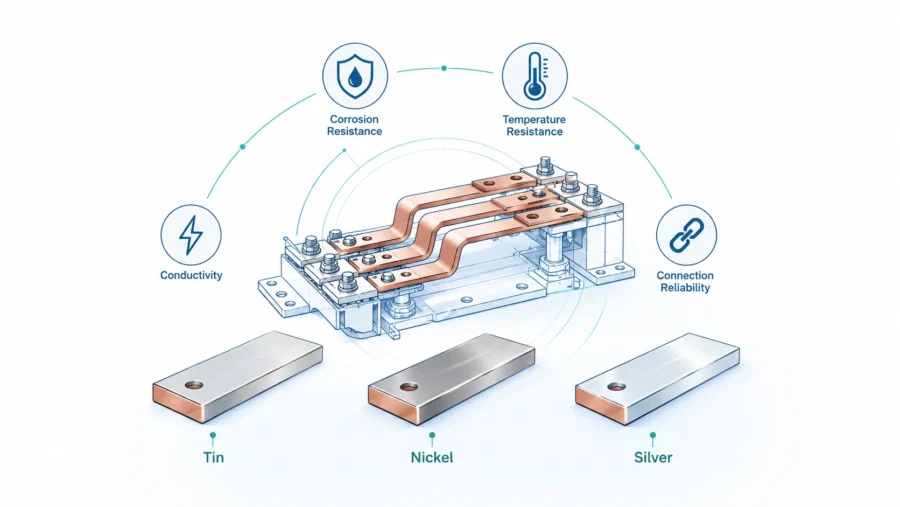
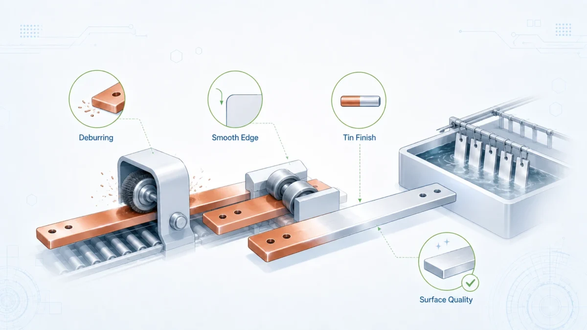
For high-current joints, the buyer should also define the surface finish and plating requirement on the terminal area. Tin plating is common for many power connections because it can support solderability, corrosion protection, and practical contact performance. Silver plating may be selected for higher-performance contact surfaces. Nickel may be used as a diffusion barrier or protective layer in certain environments, but it has different conductivity and contact behavior from copper or silver. The manufacturing route should match the joint design rather than treating plating as a cosmetic option.
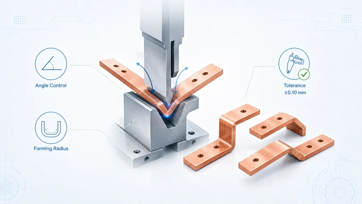
Bending and forming: building the three-dimensional current path
Bending is often the stage that separates a basic copper supplier from a true rigid busbar manufacturer. A flat copper blank can be measured easily, but a formed three-dimensional busbar must satisfy angles, offsets, hole positions, terminal pad orientation, and assembly clearances after springback. Copper thickness, temper, grain direction, bend radius, bend length, tooling condition, and bend sequence all affect the final result.
A typical formed rigid busbar may require several bends. The sequence matters because one bend can block access for a later bend. A terminal pad may need to stay flat while another section is formed. A long busbar may twist if bending forces are not balanced. A narrow feature near a bend may distort. For repeat production, manufacturers often use CNC bending equipment, custom forming tools, gauges, or dedicated fixtures to control the geometry.
Minimum bend radius is one of the most practical design rules. The Copper Development Association’s busbar ampacity page notes that the minimum bending radius for copper is equal to the thickness of the bar, while aluminum requires a larger radius in that reference context. This is a useful starting point, not a universal rule for every grade, temper, plating condition, or cosmetic requirement. If a busbar will be plated before bending, a tight bend may crack or thin the plating. If it will be insulated after bending, the bend must also allow reliable coating or sleeve placement.
Springback should be expected. After bending, copper partially returns toward its original shape. The amount depends on material temper and geometry. Experienced manufacturers compensate through tooling angle, bend allowance, and process trials. For prototypes, sample measurement should be used to refine the bend program before production quantities are released.
| Bending factor | Effect on finished busbar | Practical control method |
|---|---|---|
| Copper temper | Controls formability, stiffness, and springback | Match temper to bend radius and mechanical requirement |
| Inside bend radius | Affects cracking risk and current path shape | Use radius appropriate to thickness and surface requirement |
| Grain direction | Can affect cracking and bend quality | Review blank orientation for critical bends |
| Bend sequence | Determines whether later bends are physically possible | Simulate or fixture complex 3D forms before production |
| Hole near bend | Can deform or shift during forming | Move hole, form first then drill, or use controlled tooling |
| Terminal pad flatness | Affects contact resistance and assembly stress | Use forming support and final flattening/inspection if required |
| Plating timing | Plating before forming may crack; plating after forming may be harder to fixture | Select sequence based on coating, geometry, and contact needs |
For compact assemblies, formed busbars may need tight offsets to pass around components. In these cases, the drawing should define functional datums and inspection points. Instead of measuring every theoretical surface, buyers should identify the mounting interface, terminal plane, clearance zone, and insulation boundary that matter most to final assembly.
Deburring, edge rounding, and surface conditioning
Deburring is not a minor finishing task. It is a reliability and safety operation. Sharp copper edges can cut insulation, damage gloves, scratch adjacent components, create metal debris, and increase the chance of electrical stress concentration. A burr around a hole can prevent a washer or terminal lug from seating flat. A burr on a plated surface can become a corrosion initiation point. In insulated busbars, burrs can pierce heat-shrink tubing or create coating thin spots.
Common deburring methods include manual filing, abrasive belt finishing, tumbling, vibratory finishing, brushing, chamfering, edge rounding machines, countersinking hole edges, and polishing. The correct method depends on part size, thickness, quantity, edge requirement, and surface finish. A large formed busbar with critical terminal pads may need controlled manual or semi-automatic deburring rather than aggressive tumbling that could dent surfaces. Small flat copper blanks may be well suited for vibratory finishing before plating.
Buyers should specify edge requirements in functional terms. Instead of saying only “no burr,” define whether the part needs safe-to-touch edges, insulation-safe edges, a maximum burr height, a visible chamfer, or a controlled edge radius. For most industrial busbar projects, a practical drawing note such as “remove burrs and sharp edges” is helpful, but critical applications may need more specific criteria.
| Edge requirement | Typical reason | Suggested way to communicate it |
|---|---|---|
| General deburr | Prevent handling injury and remove loose metal | “Deburr all edges; no loose burrs allowed” |
| Insulation-safe edge | Prevent sleeve or coating damage | “Round edges contacting insulation; no sharp corners” |
| Contact pad control | Ensure flat electrical joint | “No raised burrs on mating surface; inspect terminal pad flatness” |
| Cosmetic finish | Visible copper component or customer-facing assembly | “Uniform brushed finish; scratches beyond agreed sample not allowed” |
| High-voltage spacing area | Reduce electrical stress and avoid coating thin spots | “Smooth radius on edges near insulation boundary” |
Surface conditioning also includes removal of processing oil, fingerprints, oxide, abrasive residue, and particles. Clean copper is essential before plating, insulation, adhesive bonding, or final packaging. If the busbar is shipped bare copper, the packaging may need anti-tarnish paper or sealed bags depending on storage and shipment conditions.
Cleaning and preparation before plating or insulation
Copper surfaces change quickly when exposed to air, handling oils, humidity, cutting fluids, and polishing compounds. Before plating or insulation, the part must be cleaned. The cleaning route may include alkaline degreasing, ultrasonic cleaning, acid activation, rinsing, drying, and controlled handling. The exact sequence depends on the subsequent finish.
For plating, poor cleaning can cause blistering, peeling, stains, pits, dark spots, or uneven thickness. For insulation, poor cleaning can reduce adhesion or create voids under coating. For bare copper contact surfaces, poor cleaning can increase initial contact resistance and reduce consistency between samples and production batches.
Buyers do not need to define every chemical step, but they should ask whether the supplier controls surface preparation. This is especially important when the busbar will be tin plated, silver plated, nickel plated, powder coated, epoxy coated, overmolded, laminated, or heat-shrink insulated.
Handling after cleaning is also important. If workers touch cleaned terminal pads with bare hands, oils and salts may return to the surface. If parts are stacked directly on each other, scratches can occur before plating. If cleaned parts are left in humid air, oxide can return. Process discipline matters as much as the cleaning chemistry.
Plating and surface treatment: contact reliability, corrosion control, and solderability
Many rigid busbars are not shipped as bare copper. Surface treatment is selected based on contact performance, corrosion resistance, solderability, environmental exposure, and customer standards. Tin plating is common in power distribution because it is cost-effective and widely understood. Silver plating is used when excellent contact performance, high conductivity, and thermal performance are required. Nickel can serve as a barrier or protective layer in selected conditions. Some applications use bare copper with anti-tarnish protection, while others require selective plating only on terminal pads.
ASTM B545 is a useful reference for tin coatings because its scope covers electrodeposited tin coatings applied to metallic articles. The ASTM overview for B545 explains that tin coatings are used to provide a low contact-resistance surface, corrosion protection, solderability, and anti-galling properties. For silver, ASTM B700 covers electrodeposited silver coatings for engineering use, including electrical contact characteristics and high electrical and thermal conductivity; the ASTM overview for B700 is a helpful reference for projects requiring silver-plated contact surfaces.
The plating decision should be made early because it affects manufacturing sequence. If the part is plated before bending, the plating operation is easier on a flat blank, but the coating may be stressed at bends. If the part is plated after bending, coating coverage on complex geometry may be harder, and fixturing marks must be managed. Selective plating reduces cost but requires masking or controlled deposition. Insulation windows and plating windows must be coordinated so that electrical contact areas remain exposed and coating does not interfere with assembly.
| Surface finish | Typical purpose | Advantages | Watch points | Common buyer use case |
|---|---|---|---|---|
| Bare copper with protection | Lowest process cost and high conductivity | Simple, no plating thickness variation | Oxidation/tarnish, storage sensitivity | Internal assemblies with controlled environment and short storage time |
| Tin plating | Contact reliability, solderability, corrosion resistance | Cost-effective, common for power terminals | Whisker concerns in some industries, thickness and adhesion control | Switchgear, cabinets, battery systems, industrial power modules |
| Nickel plating | Barrier layer, wear/corrosion resistance | Stable protective layer | Lower conductivity than copper/silver; joint design must account for it | Harsh environment, barrier under other plating, special terminals |
| Silver plating | High-performance contact surface | Excellent conductivity and contact behavior | Higher cost, tarnish and migration considerations | High-current contacts, critical power interfaces |
| Selective plating | Plate only functional areas | Saves cost, avoids unnecessary coating | Masking accuracy and edge definition | Large busbars with only terminal pads requiring plating |
Plating quality control may include thickness measurement, adhesion testing, visual inspection, coverage inspection, solderability testing, and contact area review. Plating thickness should be specified according to application needs rather than copied from another project. Too little plating may not protect the surface. Too much plating increases cost and may affect fit in tight assemblies.
Insulation, coating, and exposed connection windows
Rigid Busbars may be supplied bare, partially insulated, fully insulated except for connection pads, or integrated into an insulated assembly. Insulation is used to improve electrical separation, touch safety, phase identification, contamination protection, and assembly compactness. Common insulation approaches include heat-shrink tubing, PVC sleeves, PET or polyimide films, epoxy powder coating, fluidized bed coating, dip coating, overmolding, and laminated insulation structures.
The correct insulation method depends on voltage, operating temperature, creepage and clearance requirements, mechanical abrasion, flame rating, chemical exposure, flexibility at bends, and production volume. Heat-shrink tubing is practical for many formed busbars, but complex shapes may be difficult to cover smoothly. Powder coating provides a uniform insulated surface but requires masking of terminal windows and control of coating thickness. Film insulation can support compact laminated designs, but alignment and edge sealing must be controlled.
IEC 61439 is frequently relevant when busbars are part of low-voltage switchgear and controlgear assemblies. The official IEC page for IEC 61439-1:2020 states that it lays down general definitions, service conditions, construction requirements, technical characteristics, and verification requirements for low-voltage switchgear and controlgear assemblies. The official page for IEC 61439-2:2020 defines specific requirements for power switchgear and controlgear assemblies. Buyers should understand that the busbar itself is one component in a larger assembly, so final compliance depends on the complete design, installation, spacing, temperature rise, protection, and verification of the assembly.
Insulation windows are a critical detail. The copper must be exposed where the terminal needs electrical contact, but covered where touch protection or phase separation is required. If the window is too small, hardware may press on insulation and create poor contact. If the window is too large, creepage distance or touch safety may be reduced. The window location should be dimensioned from functional datums, not left to visual judgment.
| Insulation method | Strength | Limitation | Buyer specification point |
|---|---|---|---|
| Heat-shrink tubing | Flexible, common, economical | Can wrinkle at complex bends; window trimming required | Material, wall thickness, shrink ratio, color, voltage/temperature rating |
| PVC sleeve | Cost-effective for simple shapes | Temperature and fit limitations | Confirm operating temperature and mechanical abrasion risk |
| Epoxy powder coating | Good coverage and durable insulation | Masking and thickness control needed | Define coating thickness, adhesion, dielectric test, exposed windows |
| PET/polyimide film | Thin insulation for compact assemblies | Edge sealing and alignment critical | Define film thickness, overlap, adhesive, dielectric performance |
| Overmolding | Robust for high-volume assemblies | Tooling cost, design freeze required | Confirm material, mold flow, terminal exposure, validation plan |
| Selective coating | Insulates only required areas | Requires masking discipline | Provide clear coating map and window tolerances |
Inspection for insulated busbars may include visual check, window dimension measurement, coating thickness measurement, adhesion test, dielectric withstand test, insulation resistance test, and sample cross-section inspection. The test plan should match the voltage and risk level of the application.
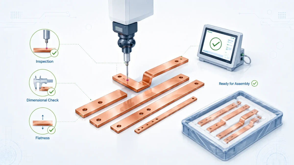
Precision finishing and final dimensional inspection
Precision finishing is the stage where the finished busbar becomes ready for assembly. It may include final flattening of terminal pads, polishing of contact areas, cleaning after plating, removal of masking residue, marking, application of labels, installation of inserts, final deburring touch-up, and packaging preparation.
Dimensional inspection should focus on functional characteristics. For a formed rigid busbar, a simple caliper check is not enough. The supplier may need a coordinate measuring machine, optical measurement, height gauge, angle gauge, go/no-go fixture, assembly fixture, or customer-matched checking fixture. For high-volume production, a dedicated checking fixture can reduce inspection time and improve consistency.
Typical inspection points include overall length, width, thickness, hole diameter, hole position, slot size, bend angle, offset height, terminal pad flatness, distance between mounting planes, coating window location, plating coverage, and part marking. The inspection method should be agreed before production, especially for critical-to-function features.
| Inspection item | Typical tool or method | Why it matters |
|---|---|---|
| Material thickness and width | Micrometer, caliper | Confirms current path and fit |
| Hole position | CMM, optical measurement, checking fixture | Prevents assembly misalignment |
| Bend angle and offset | Angle gauge, CMM, fixture | Ensures 3D fit in enclosure |
| Terminal pad flatness | Surface plate, feeler gauge, CMM | Supports low-resistance contact |
| Burr and edge quality | Visual inspection, tactile check, magnification | Protects insulation and installers |
| Plating thickness | XRF or coating thickness measurement | Confirms surface treatment requirement |
| Insulation thickness | Coating gauge or sample section | Supports dielectric performance |
| Exposed window location | Visual template, caliper, CMM | Ensures correct electrical contact and creepage |
| Electrical resistance | Micro-ohmmeter, four-wire method | Detects abnormal joints or material issues |
| Marking and traceability | Visual and label check | Prevents assembly mix-up and quality disputes |
Electrical resistance testing is particularly useful for assemblies, welded joints, laminated sections, or busbars with attached terminals. For a simple solid rigid busbar, resistance is mainly determined by geometry and material, but testing can still identify abnormal material or poor joining. The four-wire Kelvin method is preferred for low-resistance measurement because it reduces the influence of lead resistance.
Final inspection data can be delivered as a simple inspection report, full dimensional report, material certificate package, plating certificate, coating report, first article inspection, or PPAP-style documentation depending on buyer needs. The documentation level should be defined before quotation because it affects cost and lead time.
Ampacity, temperature rise, and practical data for buyer discussions
Ampacity is one of the most misunderstood topics in busbar purchasing. A busbar does not have one universal current rating. The rating changes with installation environment, temperature rise limit, enclosure ventilation, bar orientation, surface condition, number of parallel bars, spacing, AC frequency, and adjacent heat sources. For this reason, published ampacity tables are useful references, but they are not substitutes for engineering verification in the actual assembly.
The Copper Development Association provides ampacity tables for rectangular copper busbars. Its Table 1 for copper No. 110 busbars notes that ampacities in the table are for busbars having an emissivity of 0.4. Its DC ampacity page notes the 30°C rise above 40°C ambient assumption and gives orientation and spacing notes. These details are important because a busbar inside a closed cabinet will not behave exactly like a busbar in open air.
The following table is not a substitute for final design verification. It is a practical RFQ discussion tool to help buyers understand the relationship between copper size and process questions.
| Example busbar size | Cross-section area | Manufacturing implication | Buyer discussion point |
|---|---|---|---|
| 20 mm x 3 mm | 60 mm² | Easy to cut and bend, low copper mass | Suitable only for lower current paths; confirm temperature rise |
| 30 mm x 5 mm | 150 mm² | Common cabinet size, moderate stiffness | Confirm bend radius, hole size, and terminal hardware |
| 50 mm x 6 mm | 300 mm² | Good balance of capacity and formability | Review pad flatness and plating sequence |
| 80 mm x 8 mm | 640 mm² | Higher copper mass, stronger forming force | Confirm equipment capacity, bend springback, and packaging |
| 100 mm x 10 mm | 1,000 mm² | Heavy busbar, large terminal area | Review lifting/handling, plating fixturing, and flatness control |
| 120 mm x 12 mm | 1,440 mm² | Very high stiffness and cost impact | Confirm whether parallel thinner bars or design changes reduce risk |
A buyer should avoid selecting a busbar size by copying another cabinet unless the installation conditions are similar. Instead, provide the supplier with current, voltage, temperature rise target, enclosure information, and duty cycle. For high-current assemblies, thermal simulation, prototype measurement, or temperature-rise testing may be needed. The goal is not to maximize copper size blindly; the goal is to meet performance safely with a manufacturable, cost-effective design.
Standards and reference documents buyers may mention in RFQs
Rigid Busbars can be used in many industries, so the applicable standard depends on the final product and market. A busbar used inside a low-voltage switchgear assembly may be reviewed differently from a busbar used in an EV battery pack, a power converter, a UPS module, or a custom industrial machine. The busbar supplier can manufacture to drawings and agreed requirements, but final product compliance belongs to the complete assembly and certification plan.
| Reference | Why it may matter | How buyers can use it in an RFQ |
|---|---|---|
| ASTM B187/B187M | Copper bus bar, rod, bar, and shapes; dimensional, mechanical, resistivity, and chemistry requirements | Specify copper grade/temper and certificate expectations |
| Copper Development Association busbar ampacity tables | Practical reference for copper busbar ampacity assumptions | Use as early sizing guidance, not as final approval alone |
| ASTM B545 tin coating | Electrodeposited tin coatings for contact resistance, corrosion protection, solderability | Define tin plating standard, thickness, adhesion, and surface requirements |
| ASTM B700 silver coating | Electrodeposited silver coatings for electrical contact characteristics | Use for high-performance plated contact areas when required |
| IEC 61439-1:2020 | General requirements for low-voltage switchgear and controlgear assemblies | Confirm assembly-level verification expectations with panel builder or OEM |
| IEC 61439-2:2020 | Specific requirements for power switchgear and controlgear assemblies | Relevant when busbars are used in PSC assemblies |
| International Copper Association recycling brief | Copper can be recycled repeatedly without loss of performance | Useful for sustainability documentation and material circularity messaging |
Buyers should not overload an RFQ with standards that do not apply. A better approach is to state the final application, target market, applicable assembly standard, and required documentation. The busbar supplier can then align material, process, inspection, and documentation with the real need.
Quality control plan from prototype to mass production
A prototype busbar proves that the design can be made. Mass production proves that it can be made repeatedly. These are not the same thing. A prototype may be produced with manual adjustments, while production requires stable tooling, repeatable fixtures, inspection plans, operator instructions, and batch traceability. Buyers should ask how the supplier will transition from sample to production.
For first samples, the supplier should confirm material, dimensions, bend geometry, plating or coating, exposed windows, and visual appearance. If the sample requires correction, the drawing should be updated rather than relying on verbal instructions. After the design is frozen, the supplier can create production control documents and inspection criteria.
A practical quality plan includes incoming material inspection, in-process inspection after cutting and punching, inspection after forming, surface treatment control, insulation inspection, final dimensional inspection, electrical or resistance testing where required, packaging inspection, and outgoing quality records. Critical features should be identified on the drawing. These may include hole center distances, terminal pad flatness, insulation windows, bend offsets, and any dimension that affects assembly.
| Production phase | Control activity | Output document or record |
|---|---|---|
| Incoming material | Verify grade, thickness, width, surface, certificate | Material inspection record and certificate |
| First cut/punch | Check profile, holes, slots, burr direction | In-process inspection sheet |
| First formed part | Check bend angles, offsets, terminal planes | First article or setup approval record |
| Surface treatment | Check plating/coating thickness and coverage | Plating/coating certificate or inspection report |
| Insulation process | Check window location, adhesion, dielectric performance | Insulation inspection report |
| Final inspection | Check critical dimensions, surface, marking, packing | Outgoing quality report |
| Shipment | Confirm labels, batch traceability, packaging protection | Packing list and traceability label |
For high-volume or high-risk projects, buyers may request FAI, control plan, PFMEA, process flow chart, gauge R&R, capability data, or PPAP-style submissions. For many industrial buyers, a simpler but clear package is enough: drawing revision, material certificate, key dimensional report, plating report, and final inspection report.
Packaging and logistics: protecting precision after production
A perfectly manufactured busbar can still fail if it is poorly packed. Copper is soft compared with many structural metals, and plated or polished contact areas can be scratched during transport. Formed busbars can be bent if they are stacked loosely. Insulated busbars can be damaged if sharp terminal edges contact adjacent parts. Mixed left-hand and right-hand parts can create assembly confusion.
Packaging should match part value and geometry. Simple flat busbars may be separated by paper or film and packed in moisture-resistant cartons. Plated terminal surfaces may need protective film, anti-tarnish paper, or individual wrapping. Complex formed busbars may need foam inserts, trays, plastic partitions, or custom cartons. Heavy busbars may require wooden cases or reinforced packaging.
The packaging label should identify part number, drawing revision, quantity, lot number, material, finish, and inspection status. For global shipments, humidity control and corrosion protection should be discussed. Long ocean shipment, tropical storage, or warehouse delay can expose copper and plating to conditions that were not considered in the drawing.
Packaging is also part of production efficiency. If busbars arrive in the same orientation and sequence used on the assembly line, the buyer can reduce handling time and mix-up risk. This is especially helpful for multi-phase systems where several similar conductors differ only by small bends or hole positions.
Commercial cost drivers in rigid busbar manufacturing
The price of a rigid busbar is not determined only by copper weight. Copper mass is important, but several manufacturing and documentation factors can change the final cost. Buyers who understand these cost drivers can make better design decisions and compare quotes more intelligently.
Major cost drivers include copper grade, thickness, material utilization, number of bends, tolerance level, hole quantity, surface finish, plating type, selective masking, insulation complexity, tooling requirement, inspection level, documentation level, packaging, and order quantity. The fastest way to reduce cost is often not to negotiate unit price harder, but to remove unnecessary complexity from the design.
| Cost driver | Why it affects price | Possible optimization |
|---|---|---|
| Copper mass | Copper is the main raw material cost | Use proper ampacity/thermal review; avoid over-sizing |
| Low material utilization | Scrap copper increases effective cost | Adjust outline or nesting where possible |
| Tight tolerances everywhere | Slows production and increases inspection burden | Tighten only functional dimensions |
| Complex multi-bend geometry | Requires setup time, fixtures, and skilled forming | Simplify routing or split into practical sub-parts if beneficial |
| Full-body plating | Increases plating area and handling | Use selective plating when only contact pads require finish |
| Complex insulation windows | Requires masking, trimming, and inspection | Standardize window sizes and datum references |
| Low volume with special tooling | Tooling cost is spread over few parts | Use flexible process for prototypes; invest in tooling after design freeze |
| Heavy documentation | Requires engineering and quality time | Match documentation level to risk and customer requirement |
| Special packaging | Protects parts but adds labor and material | Use custom packaging only where damage risk justifies it |
A strong supplier should not simply accept an expensive design without comment. For example, a buyer may specify a very thick copper bar to reduce temperature rise, but parallel thinner busbars, improved ventilation, or a wider conductor may provide better thermal performance and easier forming. A buyer may specify silver plating across the whole part, when selective silver plating on contact pads is enough. A buyer may request tight tolerance on non-functional outer edges while leaving critical terminal flatness undefined. Manufacturing experience can prevent these mistakes.
What buyers should prepare before sending an RFQ
The better the RFQ package, the better the quotation. A vague inquiry such as “please quote copper busbar 1000A” forces the supplier to make assumptions. Those assumptions may later become cost changes, delays, or quality disputes. A clear RFQ allows the supplier to respond with accurate pricing, realistic lead time, and useful DFM comments.
Buyers should prepare a 2D drawing with dimensions, tolerances, material, finish, and drawing revision. A 3D model is helpful for complex formed busbars, but it should not replace a controlled 2D drawing. The RFQ should include expected current, voltage, application, operating environment, quantity, prototype needs, annual volume, surface treatment, insulation requirement, certificate requirement, and target schedule.
| RFQ information | Why it matters | Example buyer input |
|---|---|---|
| 2D drawing | Controls dimensions and tolerances | PDF drawing with revision number |
| 3D model | Helps review bends and assembly routing | STEP file for formed busbar |
| Copper grade and temper | Controls conductivity and forming | C11000, T2, C10200, soft/hard temper as needed |
| Current and duty cycle | Helps check sizing and heat risk | 800A continuous, 1200A peak for 10 seconds |
| Voltage and insulation need | Determines clearance, creepage, and coating | 750V DC, insulated body with exposed terminal pads |
| Surface finish | Affects contact and corrosion behavior | Tin plated terminal pads, bare body, or full tin plating |
| Application environment | Drives corrosion and thermal assumptions | Indoor cabinet, BESS container, EV pack, marine enclosure |
| Quantity and forecast | Affects process selection and tooling decision | 20 samples, 2,000 pcs/year after validation |
| Inspection documentation | Affects quality cost and lead time | Material certificate, plating report, key dimension report |
| Packaging requirement | Prevents damage and line-side confusion | Individual trays, phase labels, anti-tarnish protection |
For buyers who are still developing a design, it is acceptable to provide a concept and ask for engineering feedback. In that case, the supplier should clearly separate assumptions from confirmed requirements. Once the design is validated, all changes should be controlled through drawing revision.
How JUMAI supports rigid busbar manufacturing projects
JUMAI’s value is strongest when the project requires more than cutting copper to length. Rigid Busbars for modern power systems often require a combination of copper forming, precision stamping, deep-drawn accessories, insulation planning, plating coordination, and supplier-side engineering communication. JUMAI’s manufacturing background allows the project team to review the busbar as part of a complete electrical and mechanical assembly rather than as an isolated metal strip.
For early-stage projects, JUMAI can help buyers review drawings, clarify copper grade, evaluate bend feasibility, discuss plating and insulation options, and identify cost or risk drivers. For prototype projects, JUMAI can support sample production, dimensional inspection, and design iteration. For production projects, JUMAI can help control repeatability through fixtures, inspection plans, batch traceability, and packaging discipline.
This approach is aligned with JUMAI’s broader product positioning. The website presents precision copper busbars for modern energy systems and also highlights deep-drawn components, precision stamping dies, and tooling capabilities. That combination matters because many power-system buyers need related components around the busbar, not only the busbar itself. For example, a rigid busbar assembly may require a deep-drawn shield, a stamped bracket, an insulating spacer, a terminal cover, or a formed metal support. Coordinating these parts with one manufacturing partner can reduce communication gaps.
Buyers comparing suppliers should look for the following signs of manufacturing maturity:
| Supplier capability | Weak response | Strong response |
|---|---|---|
| Material selection | “We use copper” | Identifies grade, temper, conductivity, certificate, and equivalent options |
| DFM feedback | Quotes only from thickness and length | Reviews bend radius, holes, plating, insulation, and assembly fit |
| Process route | Cannot explain how the part will be made | Describes cutting, punching, forming, deburring, plating, coating, and inspection route |
| Prototype transition | Treats sample as handmade one-off | Explains how sample process becomes repeatable production |
| Inspection | Checks only overall size | Inspects critical dimensions, pad flatness, finish, and traceability |
| Documentation | Avoids records | Provides material certificate, inspection report, plating/coating report when required |
| Packaging | Bulk packs copper parts together | Protects terminal surfaces, geometry, labels, and batch traceability |
A buyer should not need to become a copper manufacturing expert to purchase Rigid Busbars successfully. But the buyer should work with a supplier that behaves like an engineering partner. That is the difference between a low-risk production component and a piece of copper that only looks right in a quote.
Practical manufacturing workflow for a custom rigid busbar order
A typical custom rigid busbar project can be organized into a practical workflow. The details change by industry, but the sequence below helps both buyers and suppliers control risk.
First, the buyer provides the drawing, 3D model if available, electrical requirements, quantity, finish, insulation, and target schedule. The supplier reviews the package and lists open questions. If the drawing is missing critical information, the supplier should not guess silently. It should ask about copper grade, bend radius, plating area, exposed windows, tolerance, terminal stack, and inspection requirements.
Second, the supplier prepares a DFM review and quotation. This includes the proposed material, process route, tooling needs, lead time, unit price, sample cost, surface finish, packaging, and documentation assumptions. If cost reduction is possible through design changes, those options should be clearly explained.
Third, samples are produced. During sample production, the supplier should record important process findings: springback behavior, bend sequence, burr direction, plating coverage, insulation fit, and packaging risk. The buyer then checks assembly fit, electrical performance, thermal behavior, and appearance.
Fourth, design changes are incorporated into the drawing. This is a critical step. If the sample was adjusted manually but the drawing was not updated, production risk remains. The final approved drawing should represent what will actually be manufactured.
Fifth, production control is established. This may include fixtures, inspection gauges, work instructions, approved samples, control plans, and packaging standards. The first production lot should receive closer inspection than mature repeat lots.
Finally, the supplier ships parts with the agreed documentation. The buyer should inspect incoming parts against the same critical features used during sample approval. If the parts are stored before use, storage conditions should protect plating, insulation, and exposed copper.
Common manufacturing problems and how to prevent them
Many rigid busbar problems are predictable. They occur when design, process, and inspection are not aligned.
One common problem is hole misalignment after bending. The flat blank may have correct holes, but the formed busbar does not fit because bend springback changes the final hole position relative to the terminal plane. Prevention requires bend sequence control, fixture inspection, and measurement of the formed part rather than only the flat blank.
Another common problem is raised burrs on contact surfaces. Even small burrs can reduce real contact area. Prevention requires defining burr direction, deburring both sides where needed, and inspecting terminal pads after punching and forming.
A third problem is coating or insulation interference at terminal pads. If the insulation window is too small or poorly located, the bolt or washer may press on insulation instead of copper. Prevention requires clear window dimensions, masking control, and final window inspection.
A fourth problem is plating damage at bends. If parts are plated before forming, bends may crack or thin the plating. If parts are plated after forming, coverage may be uneven on complex geometry. Prevention requires choosing the correct plating sequence and validating it during samples.
A fifth problem is shipping deformation. Heavy or formed copper parts can bend during transport if packed in bulk. Prevention requires separators, support points, custom trays, and clear labels.
| Problem | Likely root cause | Preventive action |
|---|---|---|
| Busbar does not fit assembly | Bend springback, wrong datum, accumulated tolerance | Use functional datums and formed-part inspection fixtures |
| High joint temperature | Poor flatness, contamination, wrong plating, low torque | Control pad flatness, finish, cleaning, and hardware stack |
| Insulation damage | Sharp edge, burr, poor trimming, transport abrasion | Edge rounding, window inspection, protected packaging |
| Plating peeling or stains | Poor cleaning or incompatible process | Improve surface preparation and plating control |
| Wrong part installed | Similar busbars not clearly identified | Add part marking, color coding, or packaging sequence |
| Cost higher than expected | Over-thick copper, unnecessary plating, excessive tolerance | Conduct DFM and value engineering before production |
The best time to prevent these issues is before the first sample is made. The second-best time is during sample review. The worst time is after mass production has shipped.
Sustainability and end-of-life value
Copper is valuable not only because it conducts electricity well, but also because it retains material value at the end of product life. The International Copper Association states that copper is 100% recyclable and can be recycled repeatedly without loss of performance. It also notes that there is no difference in quality between recycled copper and mined copper when properly processed, allowing both to be used interchangeably in many applications.
For buyers in renewable energy, EV infrastructure, energy storage, and data centers, this matters commercially. Sustainability is increasingly part of supplier evaluation, customer reporting, and product positioning. Rigid copper busbars can support this narrative because the material has a strong circularity story. However, good design still matters. Busbars that are easy to identify, remove, and separate from insulation or mixed materials are easier to recycle efficiently.
Sustainability also connects to right-sizing. Over-designed copper mass consumes more material than necessary. Under-designed copper may create heat loss and reliability problems. The most sustainable busbar is not always the smallest or the largest; it is the one that safely meets the electrical requirement with efficient material use, reliable manufacturing, and long service life.
Conclusion: precision manufacturing turns copper into dependable power infrastructure
Rigid Busbars are critical parts of modern electrical infrastructure. They appear in cabinets, inverters, battery systems, switchgear, charging equipment, data centers, and industrial power modules. Their reliability depends on much more than copper thickness. Material selection, DFM review, cutting, punching, bending, deburring, cleaning, plating, insulation, inspection, documentation, and packaging all influence the final performance.
For buyers, the most important lesson is simple: evaluate the manufacturing process, not only the quotation line item. A low unit price can become expensive if the busbar arrives with burrs, warped terminal pads, poor hole alignment, damaged plating, unclear material traceability, or packaging deformation. A professional supplier helps prevent those risks before they become production problems.
JUMAI supports buyers who need custom Rigid Busbars with practical engineering review, copper forming experience, surface finishing coordination, inspection discipline, and related metal forming capabilities. Whether the project is a compact cabinet, a renewable energy system, a data center power module, an EV power connection, or an industrial control assembly, the goal is the same: transform copper material into a precise, reliable, and cost-effective current path.
To begin a custom rigid busbar project, buyers should prepare drawings, current and voltage requirements, application environment, surface finish expectations, insulation needs, quantity forecast, and documentation requirements. With that information, JUMAI can help review the design, identify manufacturing risks, recommend practical improvements, and manufacture Rigid Busbars that are ready for real production use.
FAQ
What are Rigid Busbars?
Rigid Busbars are solid conductive bars or formed copper conductors used to distribute electrical current inside equipment. They are commonly used in switchgear, power distribution cabinets, EV systems, battery energy storage systems, data centers, inverters, and industrial machinery. Compared with flexible cables, they provide cleaner routing, repeatable assembly, strong mechanical support, and stable high-current performance.
What copper material is commonly used for Rigid Busbars?
Many rigid busbars use high-conductivity copper such as C11000 ETP copper, oxygen-free copper grades, T2 copper, or regional equivalents. The correct choice depends on conductivity, bendability, mechanical strength, cost, plating, and documentation requirements. Buyers should confirm copper grade, temper, certificate type, and conductivity requirement before production.
Should Rigid Busbars be tin plated or silver plated?
The choice depends on application needs. Tin plating is common because it offers practical contact performance, corrosion protection, solderability, and cost efficiency. Silver plating is used for higher-performance electrical contact areas where the additional cost is justified. Some designs use selective plating only on terminal pads to control cost.
Why is deburring important for copper busbars?
Deburring removes sharp edges and raised metal from cutting, punching, drilling, and forming. It helps protect insulation, improves handling safety, supports better terminal contact, and reduces the risk of loose metal debris inside electrical equipment. For insulated busbars, edge rounding is especially important because sharp copper edges can damage sleeves or coatings.
What information should be included in a Rigid Busbars RFQ?
A good RFQ should include a 2D drawing, 3D model if available, copper grade and temper, current and voltage, application environment, surface finish, insulation requirement, quantity, annual forecast, inspection requirements, packaging needs, and target schedule. The more complete the RFQ, the more accurate and useful the supplier’s quotation will be.
Can one ampacity table determine the final busbar current rating?
No. Ampacity tables are useful references, but the final current rating depends on installation conditions, ambient temperature, allowable temperature rise, enclosure ventilation, surface condition, AC or DC operation, spacing, orientation, and adjacent heat sources. Critical systems should be verified by engineering calculation, simulation, prototype measurement, or assembly-level testing.
How does JUMAI help with custom Rigid Busbars?
JUMAI helps buyers review busbar drawings, select copper material, evaluate manufacturability, plan cutting and forming, coordinate plating and insulation, control inspection, and protect finished parts during packaging. JUMAI also supports related precision stamped and deep-drawn components, which is useful when busbars require brackets, covers, terminal plates, or protective accessories.