Battery packs are becoming more compact, more powerful, and more demanding. Whether the application is an electric vehicle, a stationary energy storage system, a data center backup system, a marine battery pack, an industrial robot, a forklift, or a high-voltage test platform, the battery pack must move large amounts of current safely and repeatedly. Cells may receive most of the attention, but the electrical interconnect system often decides whether the pack is efficient, serviceable, and safe over its full life.
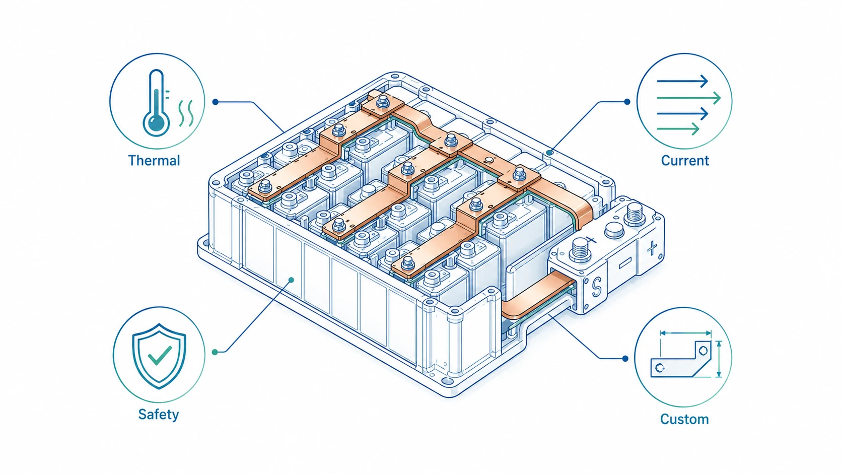
This is where Rigid Busbars become important. A rigid busbar is a formed metal conductor, usually copper or aluminum, used to connect cells, modules, contactors, fuses, relays, sensors, power distribution units, and output terminals. In many battery packs, rigid copper busbars are preferred because they provide predictable geometry, low electrical resistance, stable assembly position, good heat spreading, and clean packaging. They can also reduce wiring complexity compared with cable harnesses.
For OEMs and engineering teams, a battery busbar is not just a flat strip of copper. It is an electrical conductor, a thermal path, a mechanical part, an insulation system, a manufacturing component, and a safety-critical interface. A small design error can create excessive temperature rise, local hot spots, creepage risk, bolt loosening, vibration fatigue, plating failure, corrosion, assembly interference, or inconsistent contact resistance.
At JUMAI, our work in custom soft, rigid, and braided copper busbars is focused on this practical problem: how to turn a battery pack electrical design into reliable physical conductors that can be manufactured, inspected, assembled, and repeated at scale. This article explains the design requirements, safety standards, and customization tips that buyers should understand before sourcing rigid busbars for battery packs.
Table of Contents
Why rigid busbars matter more as battery packs scale
The global battery market is no longer a niche. According to the International Energy Agency, global electric car sales exceeded 17 million in 2024, representing more than 20 percent of new cars sold worldwide. The same IEA analysis reports that global battery demand for the energy sector reached the 1 TWh milestone in 2024, with EV battery demand growing to more than 950 GWh. These numbers matter because each increase in battery volume creates more demand for reliable internal interconnects, module bridges, power distribution conductors, and high-current terminals. See the IEA’s Global EV Outlook 2025 electric car market analysis and battery demand analysis for the latest industry context.
| Market indicator | 2024 figure from IEA Global EV Outlook 2025 | Why it matters for rigid busbars |
|---|---|---|
| Global electric car sales | More than 17 million | More battery packs need repeatable module and pack-level interconnects. |
| Electric car share of new car sales | More than 20% | Battery pack design is moving from low-volume engineering to high-volume manufacturing. |
| EV battery demand | More than 950 GWh | More modules, pack terminals, fuses, contactors, and high-current copper parts are required. |
| Total energy-sector battery demand | About 1 TWh milestone | Stationary storage, UPS, and industrial battery systems also require robust busbar design. |
| LFP share in global EV battery market | Nearly half | LFP pack architectures often use high-volume, cost-sensitive busbar designs. |
As battery pack production grows, OEMs cannot rely on hand-fitted conductors, loose cable routing, or unclear supplier assumptions. They need parts that support repeatable assembly. A rigid busbar helps because its shape, hole position, bend angle, contact area, and insulation windows can be controlled. That makes it easier to align with automated assembly, torque tools, laser welding processes, ultrasonic welding, visual inspection, and end-of-line electrical tests.
Rigid busbars also support better packaging. A cable can be bent around obstacles, but that flexibility can become a weakness when the system must hold exact spacing between high-voltage nodes and grounded structures. A formed busbar has a defined routing path. If the busbar is designed correctly, the pack designer can control clearance, creepage, service access, thermal pathways, and mechanical support more precisely.
For a broader view of rigid busbar performance in high-current systems, JUMAI’s rigid busbar design guide and custom rigid busbar EV battery efficiency article are useful companion resources.
What rigid busbars do inside battery packs
A battery pack usually contains multiple electrical layers. At cell level, small conductors connect individual cells or cell groups. At module level, larger conductors connect positive and negative module terminals. At pack level, high-current conductors connect modules to fuses, contactors, current sensors, service disconnects, charging circuits, inverters, DC/DC converters, and external output terminals.
Rigid busbars can appear in several areas:
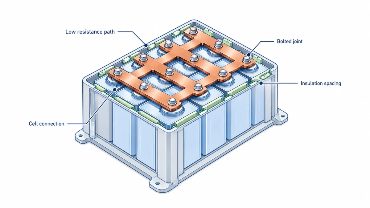
- Cell-to-cell or cell-group interconnects. These are often thinner stamped copper or aluminum parts. In cylindrical cell packs, they may include slots, fusing features, nickel plating, or nickel-clad surfaces. In prismatic or pouch cell modules, they may connect cell tabs or module terminals.
- Module-to-module bridges. These conductors link battery modules in series or parallel. They must handle pack current and maintain safe spacing from adjacent modules and enclosures.
- Main positive and negative power paths. These are usually higher-current rigid copper conductors that connect the battery stack to the power distribution unit, contactors, fuses, current sensors, and external terminals.
- Distribution and sensing interfaces. Some busbars include additional holes, tabs, small branches, or welded studs for voltage sensing, temperature sensing, pre-charge circuits, or BMS connections.
- Grounding and bonding paths. Some pack designs use rigid or braided copper conductors for equipotential bonding, EMI management, and safe fault current paths.
The right busbar type depends on the design. A fully rigid busbar is excellent when the terminals are stable and the assembly needs positional accuracy. A flexible laminated busbar may be better where movement, tolerance stack-up, vibration, or thermal expansion must be absorbed. A braided copper busbar may be better for grounding, bonding, or repeated movement. JUMAI supports all three categories, so buyers can compare rigid, flexible, and braided options without forcing the wrong conductor type into the project. For related design comparison, see Rigid Busbar vs. Cable and Flexible Busbar for EV Battery Modules.
Rigid busbar advantages compared with cables
Cables remain useful in many battery systems. They are flexible, familiar, and easy to route during early prototypes. However, as current increases and packaging space decreases, cables can become difficult to manage. A large cable harness may create inconsistent bend radii, variable contact positions, unclear service access, and extra assembly time.
Rigid busbars solve a different problem. They turn the electrical path into a fixed engineered component. That can improve repeatability, reduce assembly variation, and make the battery pack easier to inspect. The main commercial advantage is not only lower resistance. It is also lower hidden cost in installation, validation, rework, and long-term reliability.
| Comparison area | Rigid copper busbar | High-current cable | Practical buyer takeaway |
|---|---|---|---|
| Electrical resistance | Low and predictable when cross-section and joints are controlled | Low if correctly sized, but terminations may vary | Busbars help reduce variability in repeated production. |
| Packaging | Fixed 2D or 3D geometry | Flexible but can be bulky | Rigid busbars are strong for compact battery pack layouts. |
| Assembly repeatability | High | Depends on operator routing and fastening | Busbars are easier to align with fixtures and automation. |
| Thermal behavior | Can spread heat along a flat conductor | Heat may concentrate near lugs or bends | Busbars can support thermal design if contact areas are controlled. |
| Vibration tolerance | Good when supported, but poor if forced to absorb movement | Good if strain relief is designed | Use flexible links where relative movement is expected. |
| Inspection | Visual inspection and dimensional checks are straightforward | Routing and lug quality can be harder to standardize | Busbars simplify quality control in high-volume programs. |
| Customization | Requires tooling, forming, plating, insulation planning | Easier for prototypes | Busbars become more attractive as volume and repeatability increase. |
For high-power battery packs, the best design is often hybrid. Rigid busbars handle stable high-current routes. Flexible busbars or braided copper links handle movement zones, service loops, grounding, or tolerance compensation. This is why early supplier involvement is valuable. A busbar manufacturer can help decide where rigidity improves the system and where flexibility protects the system.
Core design requirements for battery pack rigid busbars
A good rigid busbar design starts from the battery pack requirements, not from a standard copper size. The engineer should define current, voltage, pack architecture, installation environment, duty cycle, temperature limit, expected life, safety standard, and assembly process. Only then should the supplier finalize material, thickness, width, plating, insulation, bending route, hole pattern, and packaging method.
The following table summarizes the design questions that should be answered before RFQ.
| Requirement area | Key questions | Why it affects the busbar |
|---|---|---|
| Electrical load | What is continuous current, peak current, pulse duration, and fault current? | Determines cross-section, thermal rise, joint design, and protective device coordination. |
| Voltage | What is nominal and maximum system voltage? | Influences insulation thickness, clearance, creepage, coating, and dielectric testing. |
| Duty cycle | Is the load continuous, intermittent, regenerative, or high-pulse? | A short pulse may be acceptable for a smaller conductor, but continuous current drives heat rise. |
| Environment | What are ambient temperature, humidity, chemical exposure, salt spray, altitude, and condensation risks? | Affects plating, insulation, corrosion protection, and creepage margin. |
| Mechanical load | Is there vibration, shock, swelling, thermal expansion, or terminal movement? | Determines support points, bend radius, slot features, and need for flexible sections. |
| Assembly process | Is the joint bolted, welded, riveted, clinched, or pressed? | Controls hole quality, flatness, plating strategy, contact area, and inspection method. |
| Validation plan | What standards and tests must the pack pass? | Busbar design should support electrical safety, abuse testing, transport, and production control. |
| Production volume | Is this prototype, pilot, or mass production? | Influences tooling investment, stamping route, inspection plan, packaging, and cost model. |
The most common mistake is sending only a width, thickness, and hole drawing. That information is not enough. For example, a 30 mm x 3 mm copper bar may look sufficient on paper, but it may overheat if the connection is enclosed, if the ambient temperature is high, if the busbar is insulated with poor heat dissipation, or if the bolted joint has high contact resistance.
Electrical design: ampacity, resistance, and voltage drop
Electrical design begins with current. However, current alone does not determine busbar size. The real question is how much heat the busbar will generate and how easily that heat can leave the system. Conductor loss is usually estimated with the equation P = I^2R, where P is power loss, I is current, and R is resistance. Resistance depends on material resistivity, length, cross-sectional area, temperature, and joint quality.
For copper, a larger cross-section reduces resistance. A shorter route reduces resistance. Good contact areas reduce joint resistance. Proper torque, clean surfaces, and suitable plating reduce the risk of local hot spots.
The simplified table below shows why conductor geometry matters. It assumes a 120 mm long copper busbar at about 20 C, using simplified conductor resistance only. It does not include bolted joint resistance, plating effects, enclosure heating, insulation thermal resistance, temperature correction, or safety margins. It is a design illustration, not a final ampacity chart.
| Copper busbar size | Cross-section | Approx. conductor resistance over 120 mm | Loss at 300 A | Loss at 500 A |
|---|---|---|---|---|
| 20 mm x 2 mm | 40 mm2 | 51.7 micro-ohm | 4.65 W | 12.93 W |
| 30 mm x 3 mm | 90 mm2 | 23.0 micro-ohm | 2.07 W | 5.75 W |
| 40 mm x 4 mm | 160 mm2 | 12.9 micro-ohm | 1.16 W | 3.23 W |
| 50 mm x 5 mm | 250 mm2 | 8.3 micro-ohm | 0.75 W | 2.07 W |
| 60 mm x 6 mm | 360 mm2 | 5.7 micro-ohm | 0.52 W | 1.44 W |
This table also shows why very small increases in resistance can matter. If the busbar itself loses only 1 W but one joint adds a few micro-ohms due to poor contact, the joint can become the hottest point. In a battery pack, heat at a terminal is more dangerous than heat distributed along a conductor because it can damage plastic housings, insulation, sensors, cell seals, or contactor terminals.
Temperature changes also matter. Copper resistance rises as temperature increases. A busbar that is acceptable at 20 C may show higher resistance at 80 C. Therefore, practical busbar design should include temperature correction and thermal validation under realistic enclosure conditions. JUMAI’s copper busbar ampacity calculation guide and rigid busbar thermal management guide explore this topic in more detail.
Continuous current and peak current
Battery packs often have two different current stories. The first is continuous current, such as a vehicle cruising condition, a BESS discharge cycle, or a UPS operating under load. The second is peak current, such as acceleration, regenerative braking, fault conditions, fast charging, pre-charge events, or short-term overloads.
A rigid busbar must be evaluated for both. Peak current may be acceptable if the duration is short and the thermal mass of the conductor can absorb it without exceeding temperature limits. Continuous current is more severe because the conductor reaches a steady-state temperature. For a commercial RFQ, buyers should provide:
- continuous current;
- peak current and duration;
- duty cycle profile;
- maximum ambient temperature;
- allowable temperature rise;
- insulation temperature rating;
- terminal temperature limit;
- cooling method and airflow condition.
Without this information, the supplier can only guess. A responsible supplier may give a conservative quotation, which can increase copper mass and cost. A better approach is to share the real load profile so the busbar can be optimized.
Voltage drop and efficiency
Voltage drop is usually small in a well-designed battery busbar, but it is still important. High current multiplied by small resistance can create both energy loss and measurement error. In battery packs with precise BMS monitoring, uneven interconnect resistance can influence balancing behavior and diagnostic consistency. For high-current modules, consistent contact resistance may be just as important as low average resistance.
A low-resistance busbar also helps commercial performance. Reduced losses mean less wasted energy, lower thermal burden, and less demand on cooling. In electric vehicles, this supports range and reliability. In energy storage systems, it supports round-trip efficiency and reduced thermal stress. In industrial battery systems, it supports uptime.
Material selection: copper grade, aluminum trade-offs, and hybrid designs
Copper is widely used in battery pack busbars because it combines high electrical conductivity, high thermal conductivity, mechanical strength, formability, and a long track record in electrical systems. Aluminum is also used, especially where weight and cost are critical. However, aluminum has lower conductivity and requires larger cross-sectional area for the same resistance. Aluminum also introduces different joining and corrosion considerations, especially when connected to copper or plated terminals.
| Material option | Typical conductivity direction | Main advantage | Main concern | Common battery-pack use case |
|---|---|---|---|---|
| C11000 / ETP copper | About 100% IACS class | Excellent conductivity, availability, cost-performance balance | Can be sensitive to some high-temperature reducing atmospheres | Main rigid busbars, module bridges, power distribution conductors |
| C10100 / OFE copper | About 101% IACS class | High purity, excellent conductivity, good for special joining or vacuum-related demands | Higher cost and procurement requirements | Premium or special-process busbars, high-reliability conductors |
| T2 copper or equivalent | High-conductivity copper commonly used in Asia | Good electrical performance and supply availability | Specification must be clearly matched to international equivalent | General custom busbar manufacturing |
| 6101 / 1350 aluminum | Lower conductivity than copper | Lower density and potential weight saving | Larger section, oxide layer, galvanic interface, joining complexity | Large lightweight conductors, selected EV and ESS designs |
| Copper-aluminum transition parts | Mixed system | Helps connect copper and aluminum subsystems | Galvanic corrosion, joining quality, interface control | Hybrid packs, pack terminals, cost-weight optimized systems |
For many battery packs, copper remains the safest default for compact high-current paths. It allows smaller cross-section for a given resistance and helps spread heat effectively. This is especially valuable near contactors, fuses, pyrotechnic disconnects, current sensors, and output terminals, where layout is often crowded and thermal behavior is critical.
However, buyers should not select copper grade casually. The drawing should define material grade, temper, thickness tolerance, surface condition, and certificate requirements. A vague material note such as “copper plate” is not enough for a high-current battery pack. The difference between soft, half-hard, and hard temper can affect bending behavior, flatness, springback, terminal contact, and fatigue resistance.
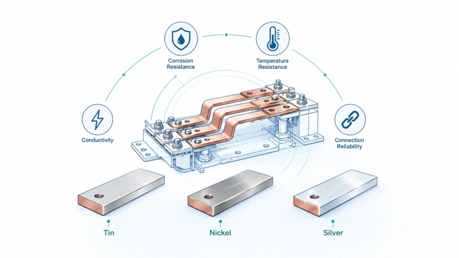
Plating and surface finish requirements
The busbar surface is not cosmetic. It controls contact resistance, corrosion behavior, solderability, weldability, and long-term joint stability. Battery pack busbars may use bare copper, tin plating, nickel plating, silver plating, or selective plating depending on the application.
| Surface option | Main benefit | Typical concern | Practical recommendation |
|---|---|---|---|
| Bare copper | Low cost and high conductivity | Oxidation and variable contact resistance over time | Use only where environment and assembly controls are suitable. |
| Tin plating | Good corrosion resistance and common electrical contact finish | Tin whisker or fretting concerns in some conditions | Common for bolted battery terminals and general busbar connections. |
| Nickel plating | Good corrosion resistance and weld compatibility in some battery systems | Higher contact resistance than silver, process control needed | Useful for cell interconnects and harsh environments. |
| Silver plating | Excellent conductivity and contact performance | Higher cost, tarnish management, selective use | Use for demanding high-current joints or low-resistance contacts. |
| Selective plating | Places finish only where needed | Requires accurate masking and process control | Strong option to balance performance and cost. |
In battery packs, selective plating is often a smart commercial choice. The entire busbar may not need an expensive finish. Only contact zones, weld zones, or sensing tabs may require a specific plating stack. The rest can be insulated, left bare, or protected by another process.
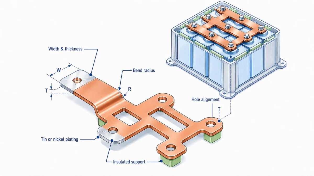
A good drawing should state plating material, plating thickness range, coverage area, adhesion requirements, salt spray or corrosion expectations, masking zones, and whether plating occurs before or after forming. Plating after forming can improve coverage on bends but may require careful masking. Plating before forming can reduce cost but may crack or thin at bend zones if not designed correctly.
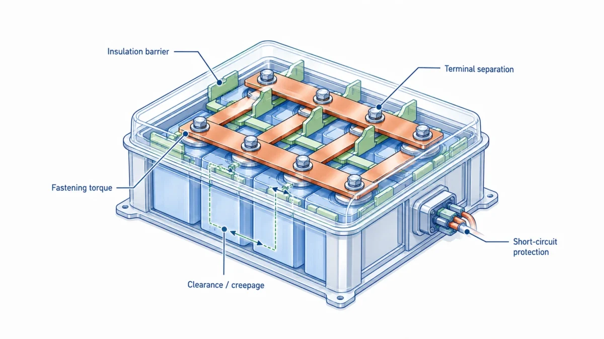
Insulation, clearance, and creepage
Battery packs operate at increasingly high voltages. In EVs, battery systems may operate from hundreds of volts to around 800 V or higher depending on platform. Stationary storage systems can use module and rack architectures with different voltage classes. As voltage rises, insulation design becomes more important.
Three concepts must be separated:
- Clearance is the shortest distance through air between conductive parts.
- Creepage is the shortest distance along an insulating surface between conductive parts.
- Solid insulation is the insulating material between conductive parts.
These are not interchangeable. A design may have enough air gap but poor creepage because the surface path is short. A coated busbar may still need adequate clearance at exposed holes, edges, terminals, and inspection windows.
IEC 60664-1 is a key reference for insulation coordination in low-voltage equipment. It covers principles, requirements, and tests for clearance, creepage, and solid insulation for equipment up to specified AC and DC voltage limits. Battery pack designers should also review the applicable vehicle, ESS, or industrial product standard because actual requirements depend on voltage, pollution degree, material group, altitude, overvoltage category, enclosure design, and the intended market.
Rigid busbar insulation options include:
| Insulation method | Typical benefit | Design concern | Use case |
|---|---|---|---|
| Heat-shrink tubing | Cost-effective and flexible for simple geometries | Can wrinkle at bends or leave imperfect edges | Prototypes, simple module bridges, lower complexity parts |
| Powder coating | Good coverage and durable surface | Masking and coating thickness control are critical | Pack-level busbars and insulated conductors |
| Epoxy coating | Strong dielectric properties and environmental protection | Process control and edge coverage matter | High-voltage battery conductors |
| PVC dipping or sleeving | Economical in some applications | Temperature and chemical resistance must be checked | Industrial and moderate-voltage systems |
| Insert-molded insulation | Excellent integration with supports and features | Tooling cost and design freeze needed | High-volume EV modules and assemblies |
| Laminated insulation film | Thin and controlled insulation layer | Edge sealing and delamination risk | Compact laminated or hybrid busbar assemblies |
The most common insulation failures occur at edges, holes, bend radii, masked contact windows, and sharp corners. A busbar may pass a simple visual inspection but fail dielectric testing because coating thins at a corner. Therefore, the mechanical design and insulation process must be developed together. Deburring, corner radius, bend radius, hole chamfer, and masking accuracy are not small details. They are part of electrical safety.
Thermal design: do not size by cross-section alone
Thermal design is where many battery busbar projects become expensive. A supplier may receive a drawing with a copper size and assume it is fixed. Later, during pack validation, the terminal area overheats. At that stage, changing the busbar may require tooling changes, enclosure changes, cable changes, validation delays, and supplier renegotiation.
A smarter approach is to evaluate thermal behavior early. The heat path includes the conductor, the joint, the terminal, the fastener, the insulation, nearby plastics, the cooling plate, the module housing, and the air inside the pack. A busbar with enough copper area can still overheat if it has a small contact patch or poor torque control.
Key thermal design variables include:
- copper cross-sectional area;
- conductor length;
- bend geometry;
- exposed surface area;
- insulation material and thickness;
- airflow or liquid cooling proximity;
- contact area at joints;
- fastener size and torque;
- flatness of mating surfaces;
- plating and oxide control;
- ambient temperature;
- pulse current duration.
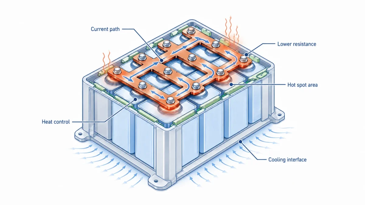
A practical battery pack design should include a temperature map. The hottest location is often not the middle of the busbar. It may be a bolt interface, a fuse terminal, a contactor terminal, a welded tab, a narrow neck, a current sensor pass-through, or a coated bend with poor heat dissipation.
| Thermal risk | Common root cause | Design response |
|---|---|---|
| Hot joint | Insufficient contact area, poor flatness, low torque, contamination | Increase pad area, control flatness, specify torque, improve plating. |
| Hot narrow neck | Copper section reduced near hole, slot, fuse feature, or bend | Add width, change cutout geometry, use larger radius, validate current density. |
| Hot insulated zone | Coating traps heat or reduces convection | Adjust coating thickness, leave non-contact thermal exposure where safe, improve cooling path. |
| Hot bend | Work hardening, coating thinning, geometry crowding | Increase bend radius, change material temper, improve forming route. |
| Hot terminal stack | Multiple interfaces create cumulative resistance | Simplify stack-up, use conductive washers only when appropriate, verify contact pressure. |
Thermal testing should be done in realistic conditions. A busbar tested in open air may look excellent, while the same busbar inside a sealed battery pack may run hotter. For validation, buyers should ask for resistance measurement, temperature rise test data, infrared thermal images if available, and clear documentation of test current, ambient temperature, test duration, mounting condition, and measurement points.
Mechanical design: vibration, shock, swelling, and assembly tolerance
Rigid busbars are strong, but they are not magic. They are excellent when the connected terminals are fixed relative to each other. They become risky when the terminals move, expand, vibrate, or shift due to cell swelling and pack deformation. Battery packs are mechanical systems as much as electrical systems.
In road vehicles, battery modules experience vibration, shock, thermal cycling, and crash loads. In stationary ESS, the mechanical environment may be less dynamic, but thermal cycling, shipping vibration, enclosure movement, and installation stress still matter. In forklifts, marine systems, mining equipment, and mobile robots, vibration can be severe.
Mechanical design should answer these questions:
- Are the two terminals connected by the rigid busbar fixed in the same module frame?
- Is there relative movement between modules?
- Will cells swell during life?
- Will the pack enclosure flex?
- Is the busbar used as a structural part or only as a conductor?
- Are support clips, spacers, insulators, or brackets needed?
- Can the busbar be installed without prying or forcing alignment?
- Are holes round, slotted, or floating to absorb tolerance?
- Does the design need a flexible link instead of a rigid link?
A common design mistake is using a rigid bridge between two modules that move relative to each other. If the busbar is forced to absorb movement, stress concentrates at bends, holes, and terminal areas. Over time, this can create cracks, loosened joints, or insulation damage. In such cases, a flexible laminated busbar or braided copper link may be safer.
JUMAI’s experience with rigid busbar compact enclosure design is also relevant to battery packs because compact packaging often creates similar clearance, routing, and assembly tolerance challenges.
Safety standards that influence battery pack busbar design
A rigid busbar by itself is usually not certified as a battery pack. However, the busbar design directly affects whether the complete battery pack can meet electrical safety, thermal, mechanical, abuse, and transport requirements. The busbar supplier must understand which standards the final product is expected to support.
The following table is a practical standards map. It is not a legal compliance checklist. Buyers should confirm the latest edition and local regulatory requirements with certification bodies, test labs, and qualified compliance engineers.
| Standard or regulation | Main scope | Why it matters for busbars |
|---|---|---|
| UL 2580 | Batteries for use in electric vehicles | Busbars must support safe operation under specified charge/discharge and abuse conditions. |
| ISO 6469-1 | Rechargeable energy storage system safety for electrically propelled road vehicles | Influences RESS safety expectations, pack architecture, and protection of persons. |
| ISO 6469-3 | Electrical safety for electrically propelled road vehicles | Influences protection against electric shock and thermal incidents in voltage class B circuits. |
| IEC 62619 | Safety requirements for industrial lithium cells and batteries | Important for stationary, UPS, telecom, utility, forklift, AGV, railway, and marine battery systems outside road vehicles. |
| UL 1973 | Batteries for stationary and motive auxiliary power applications | Affects ESS, UPS, rail, and auxiliary power battery safety requirements. |
| UL 9540 | Energy storage systems and equipment | Busbars inside a battery subsystem must support safe system-level ESS integration. |
| IEC 60664-1 | Insulation coordination for low-voltage equipment | Key reference for clearance, creepage, and solid insulation. |
| IEC 61439-1 and IEC 61439-2 | Low-voltage switchgear and controlgear assemblies | Relevant when busbars connect battery systems to power distribution assemblies or DC cabinets. |
| UN Manual of Tests and Criteria and 49 CFR 173.185 | Lithium battery transport testing and shipping requirements | Busbar design and protection should avoid external short circuits and transport damage. |
| SAE J1797 | Packaging of electric vehicle battery modules | Useful reference for module packaging topics such as terminals, retention, and module-level design features. |
The important message is simple: standards do not only affect the cell or the BMS. They affect the busbar because the busbar is part of the current path, insulation system, fault response, short-circuit risk, and mechanical structure.
What buyers should ask before certification testing
Before a pack enters certification or customer validation, the busbar package should be reviewed for:
- material certificates;
- plating certificates;
- dimensional inspection reports;
- burr and edge quality records;
- dielectric withstand test plan for insulated busbars;
- insulation thickness data;
- contact resistance data;
- temperature rise test data;
- torque and joint stack-up assumptions;
- drawing revision control;
- packaging protection method;
- lot traceability.
If these items are missing, the pack team may pass early functional testing but fail later when the customer asks for documentation. Documentation should be treated as part of the busbar product, not an afterthought.
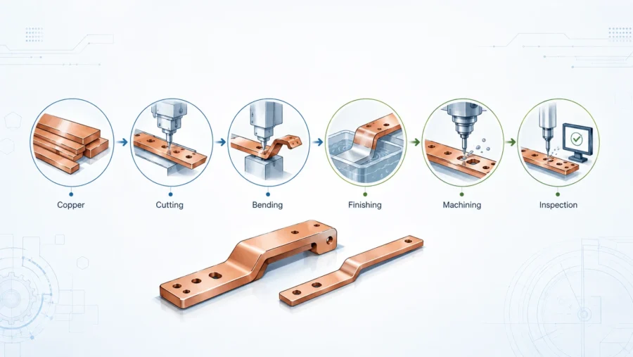
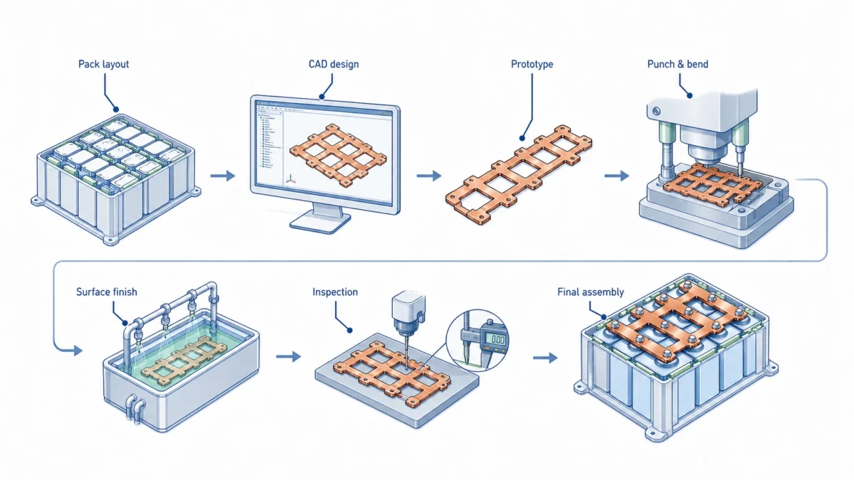
Manufacturing requirements for custom rigid busbars
Custom rigid busbar manufacturing usually includes material preparation, cutting or stamping, punching, CNC bending, deburring, cleaning, plating, insulation, marking, inspection, and packaging. For small batches, laser cutting or CNC punching may be efficient. For high-volume programs, progressive stamping or dedicated tooling may reduce cost and improve repeatability.
A typical manufacturing flow may look like this:
| Manufacturing step | What must be controlled | Battery-pack risk if ignored |
|---|---|---|
| Material sourcing | Grade, temper, thickness, coil or plate condition | Wrong conductivity, springback, cracking, or poor flatness. |
| Cutting / stamping | Profile accuracy, edge condition, hole location | Assembly interference, short creepage path, burr-related insulation failure. |
| Punching | Hole diameter, hole-to-edge distance, pad geometry | Poor terminal alignment or reduced contact area. |
| Bending | Bend radius, bend angle, bend sequence, grain direction | Cracking, dimensional error, coating thinning, installation stress. |
| Deburring | Burr height, edge radius, surface scratch control | Insulation damage, arcing risk, operator injury. |
| Cleaning | Oil, oxide, particles, residues | Poor plating adhesion or high contact resistance. |
| Plating | Thickness, adhesion, masking, corrosion resistance | Joint instability, corrosion, inconsistent welding. |
| Insulation | Coating thickness, masking, edge coverage, dielectric strength | Electrical safety failure or field short circuit. |
| Marking | Part number, polarity, revision, lot code | Assembly mistakes and poor traceability. |
| Packaging | Surface protection, anti-deformation, insulation protection | Bent parts, scratched coatings, contaminated contact areas. |
For thin-gauge parts or high-volume cell interconnects, tooling design becomes especially important. Burr height, flatness, and terminal feature repeatability are difficult to control without a disciplined tooling strategy. JUMAI’s article on metal stamping dies for thin-gauge copper busbar parts explains why die engineering matters when moving from prototype to production.
Customization tips for better battery pack busbars
The best custom busbar is not always the thickest or most expensive one. It is the one that meets current, thermal, mechanical, safety, assembly, and cost requirements with the least unnecessary risk. The following tips can help OEM buyers and engineers reduce design mistakes.
Define the real current profile
Do not specify only “500 A busbar” or “800 A busbar.” Provide continuous current, peak current, pulse duration, duty cycle, ambient temperature, maximum allowable busbar temperature, and cooling condition. This allows the supplier to avoid both under-design and over-design.
Share the pack layout early
A 2D drawing is useful, but a 3D layout is better. Busbar design depends on nearby cells, module walls, brackets, covers, screws, harnesses, cooling plates, and service tools. If possible, share STEP files or at least interface geometry. This helps avoid collision, impossible bends, and assembly problems.
Separate contact zones from insulated zones
The drawing should clearly mark conductive contact areas, masked plating areas, insulation coverage, exposed windows, sensor tabs, and no-coating zones. Ambiguous insulation boundaries create quality problems and rework.
Control edge quality
Edges matter in high-voltage battery packs. Sharp edges can damage insulation, concentrate electric field stress, cut protective films, and create handling risk. Specify deburring, edge radius, and burr direction where needed.
Do not ignore bend radius
Copper can crack if the bend radius is too small for the material thickness and temper. A larger bend radius may slightly increase space, but it improves forming reliability and coating durability. If space is tight, involve the supplier before freezing the design.
Use slots carefully
Slotted holes can help absorb assembly tolerance, but they also reduce contact area and may create sliding under vibration if the joint is not designed correctly. Use slots only where they solve a real tolerance problem, and confirm washer size, torque, and contact pressure.
Design joints as systems
A busbar joint includes busbar, terminal, plating, fastener, washer, torque, surface finish, flatness, and assembly access. Do not evaluate the copper part alone. Many high-current failures start at the joint, not in the middle of the conductor.
Avoid forcing rigid busbars to absorb movement
If modules move relative to each other, use a flexible section, laminated busbar, or braided copper link. Rigid busbars should not be used as springs unless the design has been validated for fatigue and stress.
Plan for inspection
Add features that make the part easy to inspect. Clear datum points, accessible measurement surfaces, defined hole positions, visible polarity marks, and traceability codes help production quality.
Consider packaging from the beginning
Insulated busbars can be damaged during shipping. Thin copper parts can bend. Plated contact areas can scratch or oxidize if packed poorly. Ask the supplier how parts will be separated, protected, labeled, and shipped.
RFQ checklist for rigid battery busbars
A strong RFQ reduces quotation ambiguity. It also helps suppliers quote the same technical basis, which makes comparison fairer.
| RFQ item | What to include | Why it matters |
|---|---|---|
| Drawing | 2D drawing with dimensions, tolerances, material, plating, insulation, revision | Controls manufacturing and inspection. |
| 3D file | STEP or similar model | Helps check bending, collision, and assembly route. |
| Electrical data | Continuous current, peak current, duty cycle, voltage, fault current | Allows ampacity and thermal review. |
| Environment | Ambient temperature, humidity, salt spray, chemicals, altitude | Guides plating, insulation, and creepage margin. |
| Standard target | UL, IEC, ISO, customer standard, internal validation | Aligns documentation and test assumptions. |
| Connection method | Bolted, welded, riveted, soldered, ultrasonic welded, laser welded | Controls surface finish and terminal geometry. |
| Mating parts | Terminal material, plating, fastener, washer, torque | Prevents contact resistance and galvanic problems. |
| Insulation requirement | Material, thickness, dielectric test voltage, masked zones | Prevents electrical safety ambiguity. |
| Quantity stage | Prototype, pilot, PPAP-style approval, mass production | Determines tooling and cost strategy. |
| Documentation | Material certificate, plating report, inspection report, test data | Supports customer approval and traceability. |
Buyers should be careful with unit price comparison. A cheaper busbar may become more expensive if it has burrs, warped bends, wrong plating, poor masking, unclear traceability, or no inspection data. For battery packs, the cost of a failed busbar includes not only the part cost but also validation delay, pack rework, customer complaints, and safety risk.
Design for manufacturability: make the part easy to produce repeatedly
Design for manufacturability, or DFM, is one of the most valuable supplier contributions. A busbar that works in a prototype may not be stable in production. Small changes can reduce cost and risk without changing the electrical function.
Common DFM improvements include:
| Original design issue | Possible DFM improvement | Benefit |
|---|---|---|
| Hole too close to bend | Move hole or increase bend distance | Reduces deformation and improves contact flatness. |
| Sharp internal corner | Add radius | Reduces cracking risk and improves coating coverage. |
| Very narrow neck near terminal | Increase width or change cutout | Reduces hot spot and mechanical weakness. |
| Tight bend radius | Increase radius or change material temper | Improves forming reliability. |
| Overly broad plating | Use selective plating | Reduces cost while protecting contact zones. |
| Complex 3D route | Split into two parts with controlled joint or use formed subassembly | Improves manufacturability and inspection. |
| Unclear insulation mask | Add defined dimensions and tolerance for windows | Reduces coating rework and safety risk. |
| No packaging requirement | Add separator, tray, or protective film | Prevents damage before assembly. |
At JUMAI, DFM is especially important because our capabilities include not only custom copper busbars but also precision stamped components, deep-drawn components, and tooling-related parts. Battery packs often need brackets, shields, covers, spacers, protective caps, and terminal accessories. A supplier with adjacent metal forming capability can help reduce interface problems between the busbar and the surrounding mechanical system. For a broader view of custom copper busbar solutions, see JUMAI’s custom precision copper busbars guide.
Quality control: what to inspect before shipment
Battery busbar quality control should combine dimensional, electrical, surface, insulation, and documentation checks. The exact inspection plan depends on the project stage and customer requirements. Prototype parts may need flexible engineering feedback. Mass production parts need repeatable control limits.
A practical inspection plan may include:
- material verification and certificate review;
- thickness measurement;
- width and profile measurement;
- hole position and diameter inspection;
- bend angle and 3D shape inspection;
- flatness of terminal pads;
- burr and edge condition check;
- surface scratch and contamination inspection;
- plating thickness and adhesion test;
- insulation thickness measurement;
- dielectric withstand or hi-pot testing for insulated parts;
- contact resistance or micro-ohm testing where required;
- marking and polarity verification;
- packaging inspection.
| Inspection item | Typical method | What it prevents |
|---|---|---|
| Hole location | Caliper, gauge, CMM, optical inspection | Assembly misalignment and forced installation. |
| Flatness | Surface plate, gauge, CMM | High contact resistance at terminals. |
| Burr height | Visual, tactile, microscope, burr gauge | Insulation damage and clearance risk. |
| Plating thickness | XRF or plating report | Poor corrosion resistance or contact instability. |
| Insulation dielectric strength | Hi-pot or dielectric test | Electrical breakdown in high-voltage pack. |
| Resistance | Micro-ohmmeter | Excessive loss or process inconsistency. |
| Traceability | Lot code and documentation | Difficult root-cause analysis after field issue. |
For safety-critical programs, buyers may request FAI, PPAP-style documentation, control plans, capability studies, or special characteristic tracking. These requirements should be discussed before quotation because they affect production cost and timeline.
Common mistakes when sourcing rigid busbars for battery packs
The first mistake is treating the busbar as a commodity copper part. A battery busbar is an engineered component. It must meet electrical, thermal, mechanical, insulation, and assembly requirements together.
The second mistake is relying on generic ampacity tables. Ampacity depends on installation condition, ambient temperature, enclosure, insulation, airflow, conductor orientation, joint resistance, and allowable temperature rise. Generic tables are useful for early estimation, not final validation.
The third mistake is ignoring the joint. A busbar with a large cross-section can still fail at a small or poorly controlled contact area. Flatness, plating, torque, washer choice, and mating terminal condition matter.
The fourth mistake is using a rigid busbar where movement is expected. If modules move, swell, or vibrate relative to each other, rigid copper may fatigue. A flexible laminated busbar or braided link may be safer.
The fifth mistake is under-specifying insulation. Coating material, thickness, masking, edge radius, and dielectric test requirements should be explicit. Otherwise, suppliers may quote different assumptions.
The sixth mistake is comparing only unit price. Low unit price can hide poor edge quality, unstable plating, weak inspection, or unclear packaging. In battery packs, the lowest-cost busbar is not the cheapest if it delays validation.
How JUMAI supports custom rigid busbar projects
JUMAI supports global customers with custom soft, rigid, and braided copper busbars, as well as related precision metal forming capabilities. For battery pack projects, our role is to help the customer turn electrical requirements into manufacturable, inspectable, and commercially practical busbar components.
A typical JUMAI project workflow includes:
- Requirement review. We review current, voltage, duty cycle, thermal limits, pack layout, terminal design, standard targets, and production stage.
- Material and process recommendation. We help compare copper grade, thickness, temper, plating, insulation, and forming route.
- DFM feedback. We review bend radius, hole location, cutouts, terminal pads, edge quality, masking, and assembly tolerance.
- Prototype manufacturing. We support sample production for fit check, electrical test, and validation.
- Inspection and documentation. We provide dimensional inspection, material/plating information, and additional test support as required by the project.
- Production planning. For volume programs, we help optimize tooling, process control, packaging, and repeatability.
For battery pack buyers, this matters because the busbar supplier should not simply manufacture the first drawing without question. A strong supplier should identify practical risks before they become validation failures.
Application examples
Electric vehicle battery packs
EV packs need high current, compact routing, low weight, controlled insulation, and strong vibration performance. Rigid copper busbars are commonly used for main power paths, contactor connections, fuse links, current sensor conductors, and module bridges where terminals are fixed. Flexible busbars may be used between moving modules or where tolerance compensation is required.
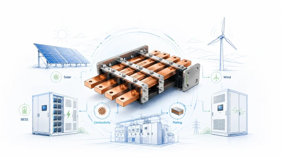
Battery energy storage systems
Stationary ESS packs may be less weight-sensitive than EVs, but they are highly sensitive to safety, thermal stability, serviceability, and compliance. Busbars may connect rack modules, fuse cabinets, DC combiner sections, and power conversion systems. Standards such as IEC 62619, UL 1973, and UL 9540 can influence design expectations.
Industrial vehicles and motive batteries
Forklifts, AGVs, mining vehicles, and marine systems may experience vibration, shock, moisture, and service abuse. Rigid busbars can improve packaging and reduce wiring complexity, but flexible links may be needed at movement interfaces.
UPS and data center backup systems
High-current battery strings in UPS and data center power systems demand low resistance, controlled temperature rise, and easy maintenance. Rigid copper busbars can help create clean, inspectable connections and reduce cable clutter. Related high-current copper design topics are discussed in JUMAI’s advanced manufacturing techniques for high-ampacity precision copper busbars.
Practical design template for engineers
A simple battery busbar specification may include the following information:
| Specification item | Example wording |
|---|---|
| Material | C11000 copper, half-hard temper, thickness 3.0 mm +/- specified tolerance. |
| Finish | Tin plating on exposed contact areas, plating thickness to agreed range, masking per drawing. |
| Insulation | Epoxy coating or heat-shrink sleeve, minimum dielectric test voltage defined by customer standard. |
| Electrical load | Continuous 300 A, peak 600 A for 10 seconds, ambient 60 C, maximum busbar surface temperature defined by pack requirement. |
| Mechanical interface | Bolted M6 terminals, torque value defined by pack assembly procedure, pad flatness requirement included. |
| Safety spacing | Clearance and creepage reviewed against project standard and voltage class. |
| Inspection | Critical dimensions, flatness, burr height, plating thickness, insulation window, lot traceability. |
| Packaging | Individual separation of plated and coated parts, contact areas protected from scratches and contamination. |
This template should be adapted to the actual project. The key is to move from vague procurement language to measurable engineering requirements.
FAQs about rigid busbars for battery packs
Are rigid busbars always better than cables in battery packs?
No. Rigid busbars are better when the system needs fixed geometry, low resistance, high repeatability, compact routing, and stable assembly. Cables or flexible busbars may be better where movement, service flexibility, or large tolerance compensation is needed.
What is the best material for battery pack rigid busbars?
High-conductivity copper is the most common choice for compact high-current paths. C11000 or equivalent copper is often a practical default. C10100 or oxygen-free copper may be used for special requirements. Aluminum can reduce weight but needs larger cross-section and careful interface design.
Does plating reduce electrical performance?
Plating changes contact behavior. A good plating system can reduce corrosion and stabilize contact resistance. Tin, nickel, and silver each have different strengths. The best finish depends on joint type, environment, cost target, and validation requirement.
How thick should a rigid busbar be?
Thickness depends on current, length, voltage, temperature rise, cooling, mechanical stiffness, bend radius, and available space. A busbar should not be sized by thickness alone. Width, cross-section, surface area, joint design, and thermal path all matter.
Can JUMAI manufacture custom shapes?
Yes. JUMAI focuses on custom copper busbars, including rigid, flexible, and braided designs. Custom shapes can include punched holes, bends, slots, contact windows, plating zones, insulation, markings, and associated metal components depending on the project requirements.
What files should buyers send for quotation?
A 2D drawing, 3D model, current and voltage requirements, material preference, plating requirement, insulation requirement, quantity, expected standards, and application notes are ideal. If the design is not final, send the pack layout and engineering assumptions so the supplier can provide DFM suggestions.
Conclusion
Rigid Busbars are critical components in modern battery packs. They help carry high current efficiently, organize compact layouts, reduce assembly variation, support thermal management, and improve inspection. However, a rigid busbar is only reliable when it is designed as part of the complete battery system.
The best battery busbar design balances current capacity, voltage insulation, thermal rise, mechanical support, plating, manufacturability, standards alignment, and production cost. It also recognizes when a rigid busbar is not enough and when a flexible or braided conductor should be added to absorb movement.
For OEMs, battery pack manufacturers, and energy system integrators, the right supplier should provide more than copper cutting. The supplier should understand current paths, terminal interfaces, surface treatment, insulation, safety expectations, quality documentation, and production repeatability. JUMAI combines custom copper busbar manufacturing with precision metal forming experience to help customers build safer, cleaner, and more commercially practical battery pack interconnect systems.
If your project requires custom rigid busbars for battery packs, share your drawing, current profile, voltage class, application environment, and production target with JUMAI. A clear early review can reduce validation risk, optimize copper usage, and help your battery system move from prototype to reliable production with confidence.