Data centers are often described through software words: cloud, AI, inference, storage, networking, latency, and uptime. But behind every digital workload is a physical electrical system that must deliver high current safely, efficiently, and repeatedly. As racks become denser and power paths become shorter, hotter, and more crowded, the electrical conductor is no longer a simple purchasing item. It becomes part of the mechanical layout, thermal design, assembly process, maintenance strategy, and risk-control plan.
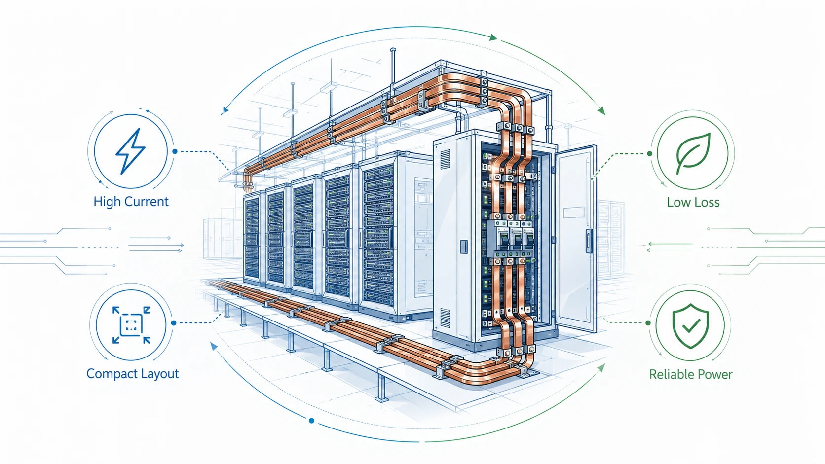
This is why Rigid Busbars are becoming more important in modern data centers. In traditional low-density rooms, cable-based power distribution could often handle rack-level loads with acceptable installation complexity. In high-density environments, especially AI, GPU, HPC, high-performance storage, and high-current UPS rooms, cable bundles can quickly become difficult to route, difficult to cool, difficult to inspect, and inconsistent from one cabinet to another. A formed copper busbar, by contrast, gives the designer a predictable current path with defined geometry, fixed connection points, controlled surface area, stable spacing, and repeatable installation behavior.
At JUMAI, rigid copper busbars sit within a broader precision connectivity portfolio that includes flexible copper busbars, braided copper busbars, stamped copper parts, deep-drawn components, and related metal forming solutions. For a data center buyer, this matters because power distribution is rarely solved by one conductor type alone. A typical electrical architecture may use rigid busbars in switchgear, UPS cabinets, battery cabinets, rack PDUs, power shelves, and high-current distribution panels, while flexible or braided busbars are used where vibration, movement, tolerance stack-up, or service access requires mechanical compliance. JUMAI’s article on high-ampacity precision copper busbars explains this product family approach in more detail.
This article explains how rigid busbars support reliable power distribution in high-density data centers. It is written for procurement managers, electrical engineers, data center infrastructure teams, OEM cabinet builders, UPS and PDU manufacturers, and project buyers who need a practical understanding of why busbar design affects safety, efficiency, thermal performance, and long-term serviceability.
Table of Contents
Why high-density data centers are changing conductor design
The first reason rigid busbars matter is simple: data centers are using more electricity, and more of that electricity is concentrated in fewer square meters. The International Energy Agency’s Energy and AI analysis estimates that global electricity consumption from data centers was about 415 TWh in 2024, equal to around 1.5% of global electricity consumption. In its base case, the IEA projects data center electricity consumption to reach about 945 TWh by 2030, representing just under 3% of global electricity consumption. The IEA also notes that data center electricity demand is projected to grow much faster than total electricity demand from other sectors.
That macro trend is important, but the local engineering challenge is even more important. Data centers are not distributed evenly across the grid. They are built in clusters, and within those clusters the load is concentrated into buildings, halls, rows, racks, and cabinets. A single AI hall can create high continuous electrical demand in a compact footprint. This changes how engineers think about conductor selection. The question is not only “can the conductor carry the rated current?” The better question is: can the conductor carry the current, control temperature rise, maintain low joint resistance, fit into the cabinet, support repeatable assembly, survive fault conditions, and remain inspectable during maintenance?
The Electric Power Research Institute’s Powering Intelligence 2026 FAQ gives another useful view of the U.S. market. EPRI estimates that U.S. data centers used about 177-192 TWh of electricity in 2024 and could use roughly 380-790 TWh by 2030, depending on how many planned projects are built and how fast they ramp up. It also states that data centers could rise from about 4-5% of U.S. electricity today to 9-17% by 2030. For electrical infrastructure suppliers, this means the market is not only growing in total size; it is also becoming more demanding in reliability, lead time, documentation, and customization.
Rack density tells the same story at the equipment level. The Uptime Institute Global Data Center Survey 2025 reports that rack densities continue to move upward, with the average modal rack density approaching 9 kW in the 2025 sample and 7.5 kW when high-density outliers are excluded. Uptime also observes stronger adoption of racks between 10 kW and 30 kW. Meanwhile, its Cooling Systems Survey 2024 shows why higher density pushes operators toward direct liquid cooling: many respondents see the need for direct liquid cooling once rack densities exceed the 20 kW range. From a conductor point of view, higher density means shorter tolerances, higher localized heat, more sensitive contact resistance, and less space for improvised cable routing.
| Industry signal | Practical meaning for power distribution | Why rigid busbars become relevant |
|---|---|---|
| Global data center electricity demand may rise from about 415 TWh in 2024 to about 945 TWh by 2030 according to IEA | More facilities require high-current electrical rooms, UPS systems, PDUs, and rack-level distribution | Repeatable busbar manufacturing helps scale infrastructure without redesigning every conductor path |
| U.S. data center use may rise from 177-192 TWh in 2024 to 380-790 TWh by 2030 according to EPRI | Regional projects need faster electrical buildout and more predictable supply chains | Custom rigid busbars can be produced to drawing and integrated into modular equipment programs |
| Uptime’s 2025 survey shows rack densities moving toward higher bands | More current must be delivered in a smaller footprint | Formed copper bars offer controlled geometry, fixed spacing, and better service access than dense cable bundles |
| Direct liquid cooling becomes more attractive above roughly 20 kW per rack | Cabinet interiors and rear-door areas become mechanically constrained | Busbar routing must avoid coolant manifolds, hose paths, service doors, airflow zones, and sensor access |
| AI systems such as NVIDIA GB200 NVL72 use rack-scale liquid-cooled architectures | Data center equipment is increasingly designed at rack or cluster scale, not only server scale | Power distribution must match rack-scale architecture with low-resistance, compact, and repeatable conductor systems |
These numbers do not mean every data center needs the same busbar. A small enterprise server room, a colocation hall, a hyperscale cloud region, an AI training cluster, a telecom edge node, and a battery-backed UPS plant all have different conductor requirements. But the direction is clear: as current density rises, the cost of poor conductor design rises with it.
What rigid busbars do inside a data center electrical system
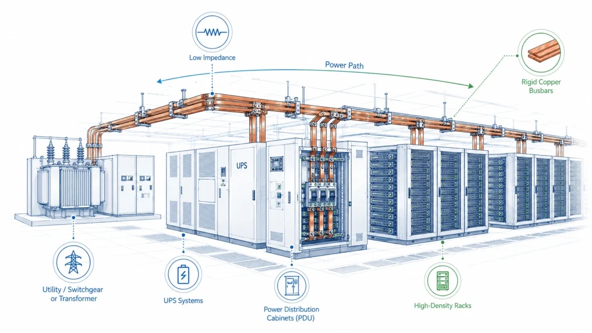
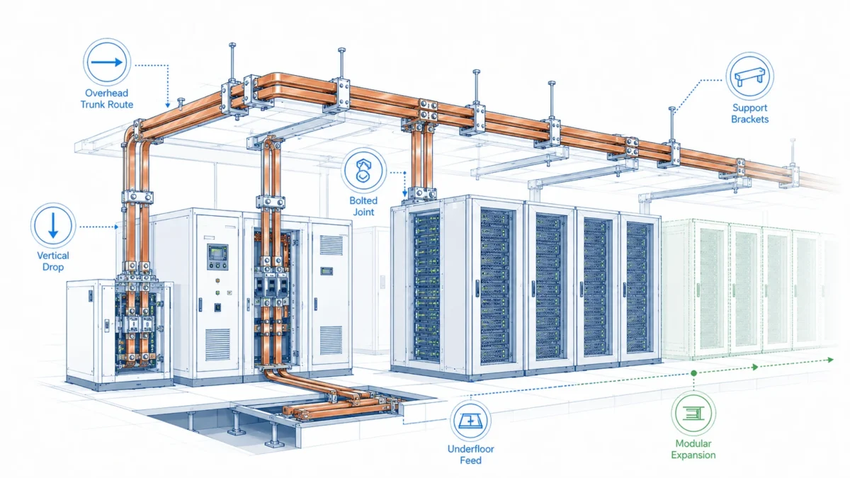
A rigid busbar is a solid conductor, usually copper or aluminum, formed into a specific geometry to distribute current between electrical devices. In data centers, rigid busbars can appear in several locations: low-voltage switchgear, busway systems, UPS cabinets, static transfer switch cabinets, battery energy storage cabinets, power distribution units, remote power panels, rack PDUs, rectifier systems, power shelves, and custom OEM power modules.
In each case, the busbar performs more than one function. Electrically, it provides a low-resistance current path. Thermally, it spreads and dissipates heat. Mechanically, it fixes the location of connection points and can support controlled spacing between phases or polarities. From an assembly perspective, it reduces wiring variability. From a service perspective, it makes the current path easier to see, inspect, clean, torque-check, and document.
The JUMAI guide on rigid busbar design for compact cabinets is directly relevant to data center equipment because many data center electrical cabinets face the same challenge: more power, more devices, and less available space. In a compact cabinet, the busbar must be designed around creepage and clearance, bend radius, hole alignment, bracket positions, insulation windows, access to bolts, heat-producing components, and airflow or coolant routing.
Rigid busbars are especially valuable where the electrical path is static. A main distribution cabinet, UPS output bus, breaker panel, rectifier output stage, or rack power shelf typically does not need a conductor that moves repeatedly. In those locations, a rigid copper busbar can offer a stronger balance of conductivity, dimensional control, heat spreading, and assembly repeatability than a flexible cable assembly.
That does not make cables obsolete. Cables remain useful for long routing distances, field-adjustable connections, and areas where installation flexibility is more important than geometry control. Flexible copper busbars and braided shunts also remain essential where movement, vibration, tolerance compensation, or service removal is required. JUMAI’s comparison of flexible copper busbar vs solid bars explains the difference between rigid and flexible conductor behavior. The stronger design approach is not to force one conductor type everywhere; it is to use the correct conductor form at each point in the power path.
| Data center location | Typical conductor challenge | Rigid busbar value | When flexible or cable may still be better |
|---|---|---|---|
| Main low-voltage switchgear | High current, fault withstand, phase spacing, breaker alignment | Strong structural path, predictable spacing, support for high-current joints | Long field routes from transformer to room may still use cable or busway |
| UPS cabinet | High current, thermal rise, compact internal layout | Low-resistance DC/AC paths, repeatable assembly, clean connection to power modules | Battery strings may need flexible links for tolerance or service access |
| PDU or RPP | Many outgoing circuits and tight terminal zones | Organized current distribution, clear phase layout, easier inspection | Field final connections may use cable whips |
| Rack PDU or power shelf | Small space, high connection density, repeated production | Precision stamped or formed copper geometry supports compact OEM design | Movable plug-in modules may need flexible conductors |
| Battery cabinet or BESS module | High DC current, short-circuit risk, thermal expansion | Rigid links can provide strong fixed paths between stable terminals | Cell expansion or removable trays may require flexible laminated busbars |
| Liquid-cooled AI rack | Power density plus coolant routing constraints | Controlled routing avoids hoses, manifolds, sensors, and service clearances | Moving trays or service loops may need flexible sections |
For a buyer, the key point is that rigid busbars are not just “copper strips.” They are engineered power distribution components. The difference between a good busbar and a risky one may appear small in a drawing but large in operation: hole position, edge burr, plating quality, bend angle, flatness, insulation cutout, contact area, and packaging can all affect installation and reliability.
Electrical efficiency: why low resistance matters at high current
Electrical losses in a conductor are governed by a simple relationship: power loss equals current squared multiplied by resistance, often written as I²R. This is easy to understand but easy to underestimate. If current doubles while resistance stays the same, heat loss increases by four times. In data center power systems, where loads may operate continuously, even small resistance differences can become meaningful over thousands of operating hours.
Copper is widely used for busbars because it combines high electrical conductivity, high thermal conductivity, formability, and strong mechanical behavior. In many busbar applications, ETP copper such as C11000 or Cu-ETP is used because it offers approximately 100% IACS conductivity in commercial practice. JUMAI’s article on busbar copper material choices for low-resistance paths discusses common copper grades and why material selection affects low-resistance performance.
However, material conductivity alone does not guarantee system efficiency. A busbar with good copper but poor joint design can still overheat. Resistance can be introduced by rough contact surfaces, insufficient contact area, oxide layers, poor plating selection, uneven bolt pressure, misaligned holes, contamination, burrs, or deformation during assembly. In high-current data center equipment, the joint is often the most sensitive part of the busbar system.
A simplified comparison shows why geometry and resistance matter. The numbers below are not a substitute for final thermal simulation, standard-based verification, or manufacturer ampacity data. They are a practical illustration of how small resistance values become heat at high current.
| Current through conductor path | Resistance of path | Approximate I²R heat loss | Engineering implication |
|---|---|---|---|
| 500 A | 20 micro-ohms | 5 W | Small, but still relevant in sealed compartments |
| 1,000 A | 20 micro-ohms | 20 W | Joint temperature rise becomes a design concern |
| 2,000 A | 20 micro-ohms | 80 W | Thermal spreading, plating, contact pressure, and ventilation matter |
| 3,000 A | 20 micro-ohms | 180 W | The joint may become a major hot spot without careful design |
| 3,000 A | 10 micro-ohms | 90 W | Reducing resistance by half reduces heat by half at the same current |
This is one of the strongest business arguments for custom rigid busbars. The buyer is not only buying copper weight. The buyer is buying controlled resistance, controlled fit, controlled heat behavior, and controlled assembly risk. A cheaper conductor that saves a small amount of copper may cost more if it creates hotter cabinets, service delays, derating, warranty claims, or field modifications.
The JUMAI copper busbar ampacity calculation guide is useful for understanding the variables behind current-carrying capacity. Ampacity depends on cross-sectional area, surface area, orientation, enclosure condition, ambient temperature, allowable temperature rise, spacing, insulation, plating, airflow, and adjacent heat sources. In a data center cabinet, the busbar is rarely in ideal free air. It may be near breakers, power modules, fans, cable trays, heat sinks, or liquid cooling pipes. That is why final ampacity should be evaluated in the actual assembly context, not only by a generic rule of thumb.
Thermal performance: busbars as both conductors and heat spreaders
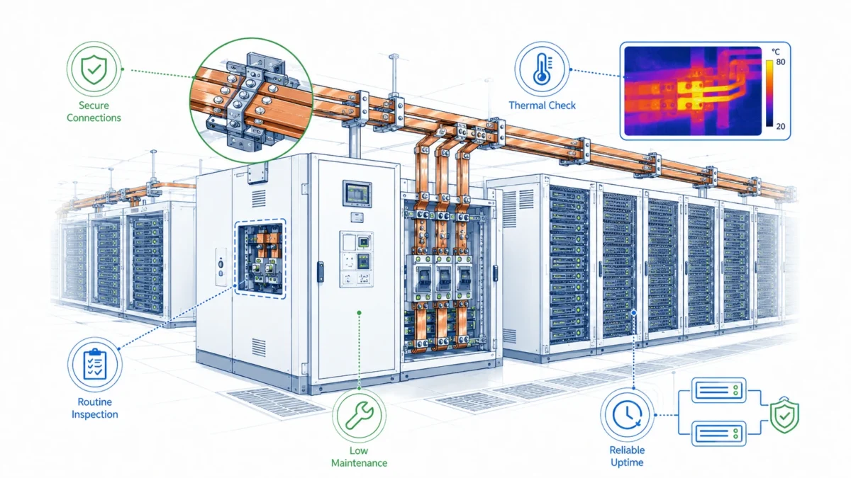
Data center reliability depends on temperature control. Facility teams often focus on cooling units, airflow management, rear-door heat exchangers, cold plates, coolant distribution units, and aisle containment. Those systems are critical, but thermal reliability also depends on the electrical path. Every conductor and every joint creates heat. If that heat is concentrated in a small area, a cabinet may fail even if the room cooling system is strong.
The ASHRAE data center resources and ASHRAE TC 9.9 work are widely used in data center thermal engineering. ASHRAE’s article on the fifth edition of Thermal Guidelines for Data Processing Environments explains that the guidance helps data center design and operation teams balance reliability and energy efficiency. The important lesson for busbar buyers is that equipment-level heat sources must be understood in relation to the facility-level environment.
A rigid busbar can help thermal management in three ways. First, copper has high thermal conductivity, so it can spread heat away from a contact point better than many alternative conductor materials. Second, the flat geometry of a busbar provides surface area for convection and radiation. Third, a custom busbar can be shaped to avoid blocking airflow or interfering with liquid cooling hardware.
But the same rigidity that creates repeatability can also create problems if the busbar is poorly designed. If a rigid busbar is too close to a heat-sensitive component, if it blocks airflow, if it concentrates current at a narrow neck, or if a bend is placed too close to a high-current bolted joint, the result can be localized temperature rise. Sharp corners, narrow transitions, stacked layers without proper contact design, and over-insulated sections can also affect heat dissipation.
A practical data center busbar review should therefore ask thermal questions early:
| Thermal design question | Why it matters | Practical design response |
|---|---|---|
| What is the continuous current, not only the peak current? | Continuous load creates sustained heat rise | Size the conductor for real duty cycle and ambient condition |
| What is the allowable temperature rise at the joint and in the enclosure? | Component ratings may be lower than copper capability | Coordinate busbar design with breaker, fuse, terminal, and insulation limits |
| Is the busbar in free air, forced air, sealed space, or near liquid cooling hardware? | Cooling environment changes ampacity | Model or test the busbar in the actual enclosure condition |
| Are there neck-down sections near holes or bends? | Reduced cross-section creates local heating | Keep high-current zones wide and smooth; avoid unnecessary bottlenecks |
| Does insulation cover most of the copper surface? | Insulation can reduce heat rejection | Use insulation windows and selective sleeving where safe and appropriate |
| Can maintenance teams inspect thermal marks or use infrared scanning? | Hidden hot spots reduce serviceability | Keep critical joints visible where possible |
Thermal reliability is one reason data center buyers should avoid treating custom busbars as commodity metal parts. A drawing that only defines length, width, thickness, and hole diameter is incomplete. A strong RFQ should also describe current, voltage, duty cycle, enclosure temperature, airflow or cooling method, allowable temperature rise, insulation requirement, plating requirement, terminal hardware, standards context, and validation expectations.
Space utilization and cabinet layout: rigid busbars reduce routing uncertainty
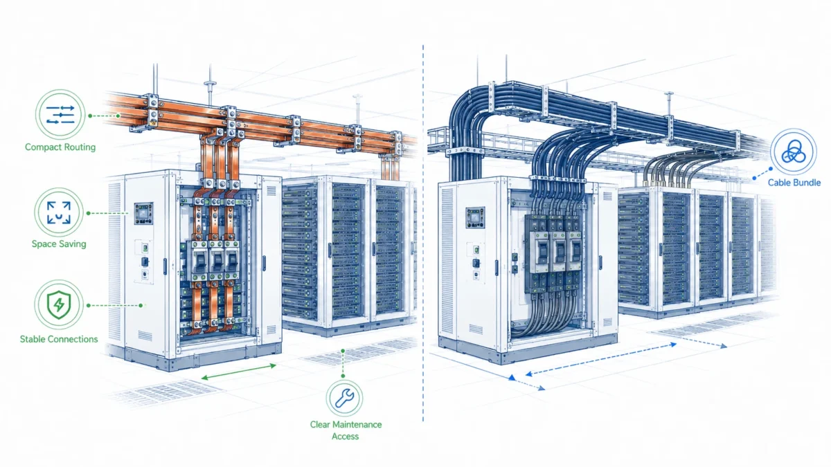
High-density data center equipment is physically crowded. A cabinet may contain breakers, contactors, fuses, monitoring sensors, control wiring, power modules, fans, ducts, bus supports, cable terminals, fiber routes, coolant manifolds, leak detection, and service handles. When conductors are routed as cable bundles, the final geometry can vary from one assembly technician to another. Bend radius, tie position, cable crossing, lug angle, and slack may all change. At low current, this variation may be acceptable. At high current and high density, it can become a reliability and service problem.
Rigid busbars reduce this uncertainty. A busbar made from a controlled drawing forces the current path into a predictable shape. Holes align with terminals. Bends define the vertical and horizontal offsets. Insulation windows expose only the required contact areas. The same conductor path is repeated across production units.
This repeatability is especially valuable for OEM manufacturers of data center equipment. A PDU manufacturer, UPS cabinet builder, battery cabinet supplier, or rack power shelf manufacturer does not want every unit to depend on field improvisation. Repeatable busbar geometry supports faster assembly, clearer work instructions, easier quality inspection, and fewer installation errors. It also supports modular product design. Once the busbar set is validated, it can be used across a product family with controlled revisions.
JUMAI’s rigid busbar design guide emphasizes materials, plating, and application requirements. In data center equipment, the design guide should be translated into a layout discipline: every busbar bend, slot, hole, tab, notch, and insulation edge should serve a purpose. Unnecessary complexity increases cost. Insufficient detail increases risk.
A rigid busbar can also support airflow management. Cable bundles can block air paths, create dead zones, or make cleaning difficult. A flat busbar can be routed along a panel wall, behind a barrier, or through a defined bus support channel. In liquid-cooled cabinets, the busbar path can be designed to preserve service access around coolant distribution manifolds and hoses. This becomes more important as AI racks and high-density power shelves combine electrical, thermal, and mechanical interfaces in one compact system.
The following simplified layout comparison shows how conductor form affects assembly behavior.
| Design factor | Cable-heavy layout | Rigid busbar layout |
|---|---|---|
| Routing repeatability | Depends on installer skill and cable dressing | Defined by manufactured geometry |
| Space use | Requires bend radius, slack, tie points, and cable separation | Compact flat paths can follow cabinet structure |
| Inspection | Cable bundles can hide joints and labels | Exposed busbars make paths easier to identify |
| Thermal behavior | Cable grouping can trap heat | Flat copper can spread heat and expose more surface area |
| Assembly speed | More manual routing and lacing | Faster installation once geometry is validated |
| Modification flexibility | Easier to adjust in the field | Requires drawing revision and remanufacture |
| Best application | Long-distance or field-variable routing | High-current, fixed, repeatable cabinet power paths |
For business buyers, the trade-off is clear. Rigid busbars may require more engineering effort before production, but they can reduce assembly time and field variability after the design is locked. That is often a good trade for equipment produced in batches or for projects where reliability is more valuable than last-minute flexibility.
Safety, standards, and verification expectations
Data center power distribution must be designed around safety. The busbar is part of a larger electrical assembly, so the applicable standard depends on where the busbar is used and where the final equipment will be installed. For example, busway products in North American contexts may be evaluated under UL 857, which applies to service-entrance, feeder, and branch-circuit busways and associated fittings within defined voltage and current ranges. Low-voltage switchgear and controlgear assemblies in many international contexts may refer to the IEC 61439 family. Data center energy efficiency metrics may use ISO/IEC 30134-2:2026, which defines Power Usage Effectiveness as a KPI for data center energy performance.
A custom rigid busbar itself is usually a component, not a complete certified assembly. That means the busbar supplier and the equipment manufacturer must align on what must be documented and tested. The busbar drawing should support the final assembly’s compliance path by controlling material, dimensions, plating, insulation, hole quality, edge condition, marking, and inspection records.
Important verification areas include dimensional inspection, material certification, plating thickness, surface condition, burr control, bend angle, flatness, insulation adhesion or sleeve quality, continuity, resistance checks when required, torque compatibility, and packaging condition. For critical applications, buyers may also request first article inspection, PPAP-style documentation, lot traceability, micro-ohm joint testing, thermal rise testing in the final assembly, or short-circuit withstand analysis performed at the equipment level.
| Verification item | What should be checked | Why it matters in data centers |
|---|---|---|
| Copper grade and temper | Material certificate, conductivity expectation, hardness or temper | Affects resistance, bending behavior, springback, and mechanical stability |
| Thickness and width | Caliper or CMM inspection against drawing | Controls cross-section, ampacity, fit, and support spacing |
| Hole position and diameter | CNC or fixture inspection | Prevents forced assembly and uneven contact pressure |
| Edge burr and corner radius | Visual and tactile inspection, burr height control | Reduces insulation damage, operator injury, and electric field concentration |
| Bend angle and bend location | Angle gauge, fixture, CMM | Ensures fit inside compact cabinets and alignment with terminals |
| Flatness at contact surfaces | Surface plate or gauge inspection | Supports low and stable joint resistance |
| Plating type and thickness | Plating report or XRF test if required | Helps control oxidation, contact behavior, and corrosion resistance |
| Insulation windows | Position, adhesion, cut quality | Maintains safety clearance while exposing correct connection areas |
| Labeling and traceability | Part number, revision, batch data | Supports service, replacement, and quality control |
| Packaging protection | Separators, caps, moisture control | Prevents scratches, deformation, and contamination before assembly |
Safety is also influenced by design for maintenance. A busbar system should make it difficult to assemble incorrectly. Phase markings, polarity markings, asymmetric hole patterns, mechanical keying, and clear insulation boundaries can all reduce error risk. For DC systems, especially battery cabinets and high-current rectifier outputs, polarity clarity is critical. For AC systems, phase spacing and phase identification matter. A small marking detail can prevent a costly installation mistake.
Material and plating choices for data center rigid busbars
Most data center rigid busbars are designed around copper or aluminum. Copper is often preferred where low resistance, compact cross-section, excellent thermal conductivity, and reliable contact behavior are priorities. Aluminum may be selected for weight and cost reasons, especially in larger busway or switchgear systems, but it requires careful attention to oxide behavior, joint preparation, thermal expansion, and compatible hardware.
For custom copper busbars, ETP copper is a common starting point because it offers high conductivity and good manufacturing behavior. Oxygen-free copper may be used in special situations where the process or application requires it, but it is not automatically necessary for every data center busbar. The correct choice depends on electrical performance, bending process, plating, operating environment, joining method, and cost target.
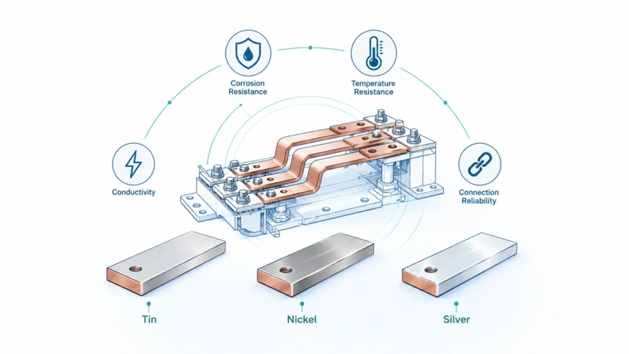
Plating is also a practical decision, not a decorative one. Bare copper can oxidize, and copper oxide may affect contact behavior over time. Tin plating is widely used for general corrosion resistance and stable contact performance in many electrical applications. Nickel plating may be considered where higher temperature or diffusion barrier performance is needed. Silver plating may be used in demanding high-current contacts where low contact resistance is critical, though it increases cost. The plating selection should match the mating material, environment, current level, temperature, and expected service life.
The JUMAI article on top benefits of rigid busbar systems describes why rigid busbars are attractive in modern high-current systems. For data centers, those benefits become stronger when material and plating are specified correctly.
| Option | Typical advantage | Typical concern | Data center use case |
|---|---|---|---|
| Bare copper | Lowest basic material/process cost, high conductivity | Oxidation and surface condition control | Internal non-critical links in controlled environments when approved by design team |
| Tin-plated copper | Good general contact stability and corrosion resistance | Tin whisker concerns may need consideration in sensitive electronics; temperature limits must be checked | PDUs, switchgear links, UPS cabinets, general high-current copper conductors |
| Nickel-plated copper | Higher temperature resistance and diffusion barrier behavior | Higher resistance than silver at contact surface; cost higher than tin | Higher-temperature zones or special interface requirements |
| Silver-plated copper | Excellent contact performance for demanding joints | Higher cost and tarnish considerations | High-current contacts, critical low-resistance interfaces, specialized equipment |
| Insulated copper busbar | Improved touch protection and phase separation | Insulation can reduce heat dissipation and complicate inspection | Compact DC systems, battery cabinets, high-density power modules |
A good RFQ should avoid vague phrases such as “copper busbar with plating.” It should define the copper grade or acceptable equivalent, temper, thickness, plating type, plating thickness, masked areas, contact surface requirements, insulation material, color, marking, and testing expectations. If the buyer is unsure, the supplier should provide engineering feedback instead of quoting blindly.
Manufacturing precision: why forming quality affects reliability
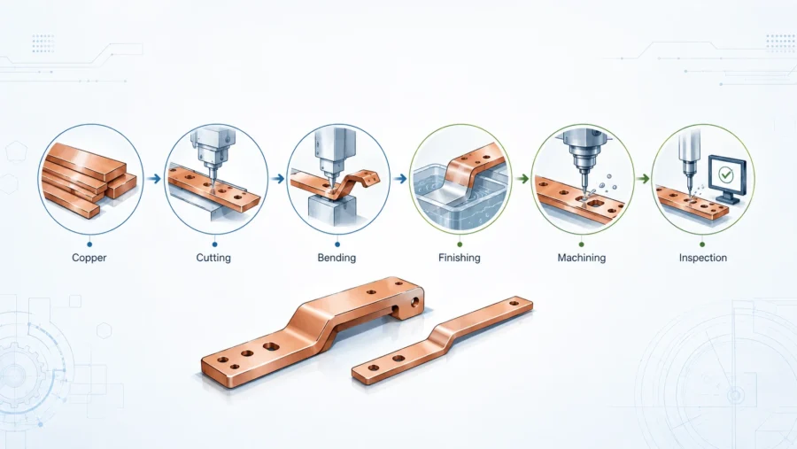
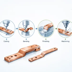
Rigid busbar manufacturing usually involves cutting, punching, stamping, bending, deburring, cleaning, plating, insulation, marking, inspection, and packaging. Each process can influence final performance. A busbar that looks simple may still require accurate tooling and process control to fit into a compact data center cabinet.
Hole quality is especially important. If holes are misaligned, assembly workers may force bolts into position, creating stress in the busbar and uneven pressure at the contact surface. If burrs remain around holes, they can damage insulation, prevent flat contact, or create debris inside the cabinet. If the contact surface is warped by punching or bending, the joint may not sit flat. That can increase micro-ohm resistance and create heat.
Bending quality is equally important. Copper springback must be controlled. Bend radius must avoid cracking or excessive thinning. Bend location must be repeatable, especially when multiple bends create a three-dimensional path. In a data center cabinet, one wrong bend angle can cause interference with a breaker, sensor, duct, door, cable gland, or coolant line.
Deburring and edge rounding deserve more attention than many buyers give them. Sharp edges are not just cosmetic defects. They can cut insulation sleeves, reduce creepage distance in polluted environments, create handling hazards, and increase the chance of surface damage during packaging. For insulated busbars, the edge condition strongly affects long-term insulation reliability.
JUMAI’s broader manufacturing background in stamping and formed metal parts supports this requirement. The company’s custom precision copper busbars guide explains how rigid, flexible, and braided busbars serve different applications, while JUMAI’s metal forming experience helps support related brackets, terminals, covers, and stamped copper components. This integration can be useful for data center OEMs because the busbar is often only one part of a power module assembly.
| Manufacturing detail | Poor control can cause | Preferred control method |
|---|---|---|
| Punching | Burrs, oval holes, deformation, poor bolt fit | Proper die clearance, tool maintenance, deburring, inspection fixture |
| CNC cutting | Edge roughness, dimensional variation | Program control, edge finishing, first article inspection |
| Bending | Angle error, cracking, terminal misalignment | Controlled bend radius, bend sequence planning, fixture verification |
| Plating | Uneven thickness, poor adhesion, masked contact error | Plating specification, pre-cleaning, thickness testing, visual inspection |
| Insulation | Poor adhesion, incorrect window, exposed edges | Defined insulation material, clean edges, window templates, peel or visual checks |
| Marking | Wrong revision, missing polarity, unclear batch | Controlled labeling and traceability process |
| Packaging | Scratches, bent tabs, contaminated contact faces | Protective separators, caps, moisture control, batch packing instructions |
From a commercial perspective, manufacturing precision protects both sides. The buyer gets fewer assembly problems and lower field risk. The supplier gets fewer disputes caused by ambiguous specifications. The best projects usually start with drawings, 3D models, electrical requirements, and open engineering discussion before price is finalized.
Data center use cases for custom rigid busbars
Rigid busbars can be used across many data center power layers. The specific design depends on whether the application is AC or DC, low-voltage or higher-voltage, open or enclosed, air-cooled or liquid-cooled, serviceable or sealed, one-off or mass-produced.
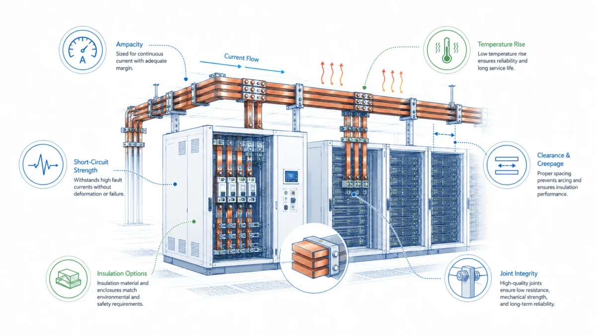
In switchgear and busway-related equipment, rigid busbars provide the main high-current path between incoming power, breakers, metering devices, protection devices, and outgoing feeders. Here, phase spacing, short-circuit withstand, support placement, and temperature rise are central concerns. The busbar must coordinate with the full assembly design and applicable standards.
In UPS systems, rigid busbars often connect rectifier modules, inverter modules, bypass paths, output breakers, battery interfaces, and DC link components. UPS cabinets demand reliability because they protect critical loads. A poor joint or overheated busbar can compromise redundancy. In modular UPS systems, busbars also support production repeatability and module alignment.
In battery rooms and battery energy storage cabinets, rigid busbars may connect battery strings, DC breakers, contactors, fuses, monitoring shunts, and output terminals. DC systems require careful polarity separation, insulation control, and short-circuit protection. Because battery systems can deliver very high fault current, the busbar design must be coordinated with protective devices and mechanical supports.
In rack PDUs, power shelves, and AI rack power distribution, rigid busbars can help organize high current in a very tight space. These systems may require small, precise copper parts rather than large flat bars. Stamped copper conductors, small formed busbars, plated terminals, and insulated copper links can reduce assembly variation in repeated production.
| Application | Typical busbar requirement | Business value of customization |
|---|---|---|
| Low-voltage switchgear | High current, phase separation, support spacing, fault coordination | Reduces field modification and supports compliance documentation |
| UPS cabinet | Compact high-current AC/DC routing, low joint resistance | Improves reliability and repeatability in mission-critical equipment |
| Static transfer switch | Fast switching path, stable geometry, thermal control | Supports predictable performance during transfer events |
| PDU/RPP | Organized distribution to many outgoing circuits | Improves assembly speed and service clarity |
| Battery cabinet | DC polarity control, insulation, short-circuit awareness | Reduces polarity error and supports safer maintenance |
| Rack power shelf | Precision small copper parts and dense connection zones | Supports OEM production scale and compact high-density design |
| Liquid-cooled AI rack | Electrical routing around cooling hardware | Helps preserve service access and avoid mechanical interference |
A useful design principle is to review the complete power chain, not one busbar in isolation. A perfectly manufactured busbar can still fail if the mating terminal is too small, the bolt stack is wrong, the surface finish is incompatible, the support spacing is excessive, or the cabinet lacks thermal management. A strong supplier should ask about the system, not only the copper dimensions.
Rigid busbars versus cable assemblies in data center projects
The choice between rigid busbars and cable assemblies should be made at the system level. Cables are flexible, familiar, and useful for field installation. They can handle routing changes and are often easier to modify late in a project. But cables occupy volume, require bend radius, need lugs, may create thermal grouping issues, and can vary in final layout.
Rigid busbars require more design certainty upfront. Once the geometry is manufactured, it is not meant to be casually adjusted in the field. But that is also the advantage. The busbar forces a known path. It can reduce labor time, eliminate cable dressing variation, improve current sharing in designed parallel paths, and make high-current connections easier to inspect.
The decision often depends on production volume. For a one-off site modification, cable may be more practical. For a repeated cabinet design, rigid busbars often deliver better total value. Tooling, drawing review, sample validation, and initial engineering time are spread across multiple units. The result can be a cleaner product with lower assembly effort and fewer hidden installation variables.
| Decision factor | Rigid busbar is usually stronger when… | Cable is usually stronger when… |
|---|---|---|
| Geometry | Terminals are fixed and space is tight | Routing is uncertain or field-dependent |
| Current | High current requires low resistance and clean heat spreading | Current is moderate and cable sizing is practical |
| Production | The same design repeats across many units | The installation is one-off or frequently changing |
| Maintenance | Visual inspection and fixed labels are valuable | Field replacement flexibility is more important |
| Thermal behavior | Cable bundling would trap heat or block airflow | Cable can be separated and cooled adequately |
| Design maturity | The cabinet layout is stable | The design is still changing late in the project |
A hybrid approach is common. A cabinet may use rigid busbars for the main internal distribution and cables for final branch connections. A battery system may use rigid bars for stable module-to-module links and flexible busbars where trays move. An AI rack may use formed copper conductors in power shelves and flexible links for removable modules. JUMAI can support this kind of mixed architecture because its busbar portfolio includes rigid, flexible, and braided copper solutions.
Procurement workflow: how to buy rigid busbars for data center equipment
Buying custom rigid busbars should not begin with a unit price request alone. The buyer should first define the operating context. This includes current, voltage, AC or DC, frequency if relevant, continuous load, peak load, ambient temperature, enclosure type, cooling method, fault requirement, standards context, installation location, mating terminals, hardware stack, surface treatment, insulation, annual quantity, prototype schedule, and documentation needs.
The next step is technical normalization. If several suppliers quote the same drawing, their assumptions may still differ. One supplier may assume bare copper, another tin plating. One may include deburring, another may not. One may quote soft copper, another half-hard copper. One may include insulation windows, another may only provide raw copper. Without normalization, the cheapest quote may simply be the least complete quote.
A strong RFQ package should include drawings and, if available, 3D files. It should specify material, thickness, tolerances, plating, insulation, hole requirements, bend requirements, marking, inspection, packaging, and revision control. It should also describe the application enough for the supplier to identify manufacturability risks. If the buyer cannot share full system details, a simplified interface drawing and requirement table can still help.
| RFQ information | Minimum useful detail | Why it helps the supplier |
|---|---|---|
| Electrical rating | Continuous current, peak current, voltage, AC/DC | Supports sizing, plating, insulation, and thermal review |
| Environment | Ambient temperature, enclosure, cooling method, humidity/corrosion risk | Affects ampacity, plating, and insulation choice |
| Mechanical interface | Terminal sizes, bolt stack, support points, available space | Prevents fit and contact problems |
| Drawing package | 2D drawing plus 3D model if possible | Supports accurate quoting and manufacturability review |
| Material | Copper grade or acceptable equivalent, temper | Controls conductivity, bending, and springback |
| Surface treatment | Bare, tin, nickel, silver, masking details | Controls contact behavior and corrosion resistance |
| Insulation | Material, color, thickness, window locations | Supports safety and assembly clarity |
| Quality documentation | Certificate, FAI, inspection report, traceability | Aligns supplier process with project risk level |
| Quantity and schedule | Prototype quantity, pilot quantity, volume forecast | Helps choose tooling and production route |
| Packaging | Contact protection, labels, batch separation | Prevents transport damage and assembly confusion |
Prototype validation should not be skipped. A sample busbar should be checked for fit, hole alignment, bolt access, bend clearance, insulation window position, contact flatness, and serviceability. If the application is high current, thermal validation should be performed in the actual cabinet or representative assembly. Only after prototype feedback is closed should the buyer lock the design for volume production.
How JUMAI supports data center rigid busbar projects
JUMAI’s role is to help customers turn electrical requirements into manufacturable copper busbar parts. For data center projects, this usually means reviewing the current path, material choice, copper thickness, bend geometry, hole layout, plating, insulation, assembly sequence, and inspection requirements. The goal is not merely to make a copper part that matches a drawing. The goal is to help the customer receive busbars that fit cleanly, carry current reliably, and support stable production.
JUMAI can support rigid busbars for static high-current paths, flexible copper busbars for tolerance compensation or service movement, and braided copper busbars for vibration or multi-directional movement. This is useful in data center electrical systems because one project may include all three conductor types. A UPS cabinet may need rigid busbars internally and flexible links to serviceable modules. A battery cabinet may need rigid busbars between fixed terminals and flexible conductors near removable trays. A rack power shelf may need small precision stamped copper conductors, plated terminals, and formed busbars.
The company’s metal forming background also matters. Data center busbars often require related parts: brackets, terminal plates, covers, shields, spacers, stamped contacts, or deep-drawn hardware. When the busbar supplier understands metal forming, it can provide more practical DFM suggestions. For example, a minor hole-position change may reduce tooling complexity. A bend relief may prevent cracking. A plating mask adjustment may improve contact reliability. An insulation window change may improve assembly safety.
JUMAI’s internal resources can help buyers prepare for discussion. The copper busbar ampacity calculation guide helps frame thermal and current questions. The rigid busbar design guide helps buyers understand material and plating decisions. The article on rigid busbar compact enclosure design is useful for cabinet engineers dealing with tight spaces. Together, these resources create a practical foundation before the buyer submits drawings for quotation.
Design checklist for reliable rigid busbars in data centers
A strong rigid busbar design should be reviewed from electrical, thermal, mechanical, manufacturing, and service perspectives. The checklist below can help buyers and engineers identify issues before prototype production.
| Review area | Key question | Recommended action |
|---|---|---|
| Electrical | Is the busbar sized for continuous current and realistic ambient temperature? | Use actual duty cycle and enclosure condition, not only peak current |
| Joint resistance | Are contact surfaces flat, clean, plated appropriately, and large enough? | Define contact area, plating, hardware, and torque strategy |
| Thermal | Are there bottlenecks, hot spots, or over-insulated zones? | Review current density, surface area, airflow, and thermal test plan |
| Mechanical | Does the busbar fit without forcing terminals into alignment? | Validate with 3D model, assembly fixture, or prototype |
| Safety | Are creepage, clearance, polarity, phase spacing, and touch protection addressed? | Coordinate with final assembly standard and insulation plan |
| Manufacturability | Are bends too close to holes or edges? Are tolerances realistic? | Ask supplier for DFM review before tooling or batch production |
| Maintenance | Can technicians see labels, access bolts, and inspect joints? | Design for service access and error prevention |
| Quality | Are inspection points and acceptance criteria defined? | Include FAI, dimensional checks, plating reports, and traceability as needed |
| Packaging | Can the busbar be shipped without scratches or deformation? | Define separators, contact protection, labels, and batch packing |
| Revision control | Can old and new versions be distinguished? | Use part number, revision, drawing date, and controlled change process |
This checklist is intentionally practical. Many busbar problems do not come from advanced electrical theory. They come from missing details: a bolt that cannot be reached, a bend that interferes with a cover, an insulation window shifted by a few millimeters, a burr that cuts sleeving, or a plating requirement that was never written into the purchase order.
Cost and business value: look beyond copper weight
The price of a rigid copper busbar is influenced by copper weight, material grade, thickness, geometry complexity, tolerances, punching, bending, deburring, plating, insulation, inspection, packaging, order quantity, and lead time. Because copper is a major cost driver, buyers sometimes focus too heavily on reducing copper mass. Optimization is good, but under-designed copper can become expensive if it causes heat rise, derating, assembly difficulty, or field failure.
The better commercial question is total installed value. A custom rigid busbar may cost more than a simple cable or raw copper strip, but it may reduce assembly time, reduce rework, improve thermal behavior, reduce service risk, and improve product appearance. For OEMs, repeatable busbars can also simplify training and quality control. For data center operators, clearer power paths can improve maintenance confidence.
The cost of a busbar defect can be much larger than the busbar itself. A delayed UPS cabinet, failed thermal test, field retrofit, damaged breaker terminal, or overheated joint can affect project schedules and customer trust. In mission-critical infrastructure, reliability has commercial value.
| Cost driver | Low-cost shortcut | Possible hidden cost | Better approach |
|---|---|---|---|
| Copper mass | Reduce width or thickness without thermal review | Higher temperature rise and derating | Optimize cross-section using current, temperature, and layout data |
| Deburring | Skip edge finishing | Insulation damage and assembly injuries | Define burr limits and edge radius expectations |
| Plating | Use vague or cheapest plating | Contact instability or corrosion risk | Match plating to environment and mating surfaces |
| Tolerance | Use loose dimensions in compact cabinet | Forced assembly and misalignment | Apply tight tolerances only where needed, with clear datum strategy |
| Documentation | Avoid inspection reports | Harder root-cause analysis and quality disputes | Request appropriate documentation for project risk level |
| Packaging | Bulk pack parts together | Scratches, bent tabs, contaminated contacts | Use protective separators and labeled packaging |
A good supplier will help identify where cost can be reduced safely. Sometimes the best saving is not thinner copper; it is a simpler bend sequence, a standard plating option, a revised hole pattern, better nesting, or a design that avoids secondary operations.
Common mistakes to avoid
The first mistake is designing the busbar too late. If the cabinet is already fixed and the busbar is forced into leftover space, the result may be complex, expensive, and thermally weak. Busbar routing should be part of the early cabinet architecture.
The second mistake is treating ampacity as a single table value. Generic ampacity tables can be useful for early estimates, but final performance depends on actual enclosure conditions. A copper bar in free air does not behave the same as a copper bar inside a crowded cabinet near heat-producing power modules.
The third mistake is ignoring the joint. Many high-current problems occur at bolted interfaces, not in the straight section of copper. Contact flatness, plating, torque, washer selection, bolt grade, surface cleanliness, and contact area all matter.
The fourth mistake is overusing rigid busbars where flexibility is required. Rigid busbars are excellent for fixed paths, but they should not be used to absorb repeated movement, major vibration, or tolerance mismatch without analysis. Flexible or braided busbars may be better in those areas.
The fifth mistake is under-specifying inspection and packaging. A busbar can be manufactured correctly and still arrive damaged if packaging is poor. Contact surfaces must be protected. Insulated parts should not be crushed or scratched. Similar part numbers should be separated and labeled clearly.
The sixth mistake is buying only on unit price. A very cheap busbar can become expensive if it causes assembly delays, failed testing, rework, or field service events. For data center equipment, the buyer should evaluate engineering support, manufacturing control, documentation, and supply consistency alongside price.
Conclusion: rigid busbars are strategic components in high-density data centers
Data centers are moving toward higher power density, more modular electrical architecture, and tighter integration between power, cooling, and mechanical design. Industry data from IEA, EPRI, and Uptime points in the same direction: data center electricity demand is growing, rack densities are rising, and AI infrastructure is making electrical design more demanding. In that environment, the conductor path inside cabinets and power equipment deserves serious engineering attention.
Rigid Busbars provide a reliable way to distribute high current in fixed, compact, and repeatable data center applications. They help reduce routing uncertainty, improve assembly consistency, support lower resistance, spread heat, organize service access, and strengthen the overall power distribution design. But the benefit depends on correct engineering. Material, plating, cross-section, joint design, insulation, bend accuracy, surface finish, inspection, and packaging all influence final performance.
For data center OEMs, UPS manufacturers, PDU builders, switchgear integrators, battery cabinet suppliers, and AI infrastructure equipment designers, custom rigid busbars should be treated as engineered components, not commodity copper strips. A well-designed busbar can improve reliability, reduce installation variability, and support scalable production. A poorly specified busbar can create thermal, mechanical, and service problems that are far more expensive than the part itself.
JUMAI supports customers with custom rigid copper busbars, flexible copper busbars, braided copper busbars, and related precision metal forming capabilities. If your project involves high-density data center power distribution, UPS cabinets, PDUs, battery systems, AI rack power paths, or compact electrical enclosures, the best starting point is a technical review of your current path, drawings, operating conditions, and validation requirements. With the right busbar design, high-density electrical systems can become cleaner, safer, easier to assemble, and more reliable over the long term.