In the intricate world of power distribution and industrial electrical engineering, the difference between a system that operates at peak efficiency and one that suffers from catastrophic failure often comes down to a single, critical component: the busbar. At JUMAI TECH, we have spent years perfecting the art of manufacturing Precision Copper Busbars, Deep-Drawn Components, and Precision Stamping Dies. We understand that whether you are designing a switchgear cabinet for a massive data center or a compact power unit for an electric vehicle, the physics remains the same. The integrity of your electrical connections defines the reliability of your entire system.
Among the various options available in the market today, the mt copper busbar stands out as a preferred choice for engineers demanding high conductivity and thermal stability. However, simply choosing high-quality material is not enough; the engineering magic lies in the sizing. Incorrect sizing can lead to dangerous overheating, energy loss through resistance, and mechanical failure under short-circuit conditions. This comprehensive guide will walk you through everything you need to know about mt copper busbar sizing, drawing on decades of industry experience to ensure your power distribution networks are built to last.
Table of Contents
The Fundamentals of MT Copper Busbar Technology
To properly size a busbar, one must first understand the material properties that dictate its performance. An mt copper busbar typically refers to high-grade copper conductors designed for medium tension or specific high-performance applications where purity and geometry are paramount. Copper is the standard-bearer for electrical conductivity, second only to silver, but with far superior mechanical properties and cost-effectiveness for industrial scale.
Conductivity and Material Purity
The performance of any mt copper busbar is rooted in the International Annealed Copper Standard (IACS). High-quality busbars are manufactured from Electrolytic Tough Pitch (ETP) copper (specifically C11000) or Oxygen-Free copper (C10100). These grades boast a conductivity rating of 100% to 101% IACS. When we size these bars, we are essentially calculating how many electrons can flow through the lattice structure of the copper without generating excessive friction, which manifests as heat. Lower purity copper, often found in budget alternatives, introduces impurities that scatter electrons, increasing resistance and requiring a larger cross-section to carry the same current.
Thermal Characteristics and Heat Dissipation
Heat is the enemy of all electrical systems. As current flows through an mt copper busbar, the internal resistance generates heat according to Joule’s First Law ($P = I^2R$). The sizing process is, fundamentally, a thermal management exercise. The busbar must have enough surface area to dissipate this generated heat into the surrounding air via convection and radiation. If the bar is undersized, the temperature will rise beyond the insulation rating of the connected components (such as stand-off insulators or circuit breakers), leading to melting, arcing, or fire. Conversely, an oversized busbar, while electrically safe, adds unnecessary weight, cost, and spatial bulk to the design, which contradicts the modern trend of compact, efficient engineering.
Calculating Ampacity: The Core of Sizing
The term “Ampacity” refers to the maximum current an electrical conductor can carry before deteriorating. Determining the ampacity of an mt copper busbar involves more than just looking up a single number in a chart; it requires a calculation that accounts for the continuous current load and the allowable temperature rise.
The Standard Current Density Rule
For a quick estimation in general switchboard designs, many engineers use a standard current density rule of thumb. A common value historically used is 2 Amps per square millimeter ($2A/mm^2$) for copper. However, as the dimensions of the busbar increase, the skin effect (discussed later) reduces the effective cross-sectional area, making this linear rule inaccurate for larger bars.
For modern mt copper busbar applications, we recommend calculating based on the specific allowable temperature rise, typically $30^\circ C$, $50^\circ C$, or $65^\circ C$ above ambient temperature. A busbar allowed to run hotter can carry more current, but this poses risks to adjacent equipment.
Understanding the “Skin Effect” in AC Systems
When dealing with Alternating Current (AC), the current distribution across the cross-section of the mt copper busbar is not uniform. The alternating magnetic field creates back-EMF (electromotive force) that pushes the current flow toward the outer edges (or “skin”) of the conductor. This means the center of a thick busbar carries very little current.
For AC frequencies of 50Hz or 60Hz, this effect becomes significant as the busbar thickness exceeds 10mm. Therefore, when sizing for high-current AC applications, it is often more efficient to use two thinner bars in parallel with a gap between them, rather than one single thick bar. This configuration increases the total surface area for cooling and reduces the skin effect resistance, optimizing the performance of the mt copper busbar.
Critical Environmental Factors and Derating
Engineers often make the mistake of sizing an mt copper busbar based on laboratory conditions (usually $20^\circ C$ or $25^\circ C$ ambient). However, real-world industrial environments are rarely this forgiving. To ensure reliability, we must apply derating factors.
Ambient Temperature Correction
If your busbar is installed inside a poorly ventilated enclosure in a factory where the ambient temperature is $40^\circ C$, the busbar cannot dissipate heat as effectively as it would in a cool room. You must apply a correction factor to reduce the rated ampacity.
For example, if a busbar is rated for 1000A at a $30^\circ C$ rise with an ambient temp of $35^\circ C$, but the actual ambient temp is $50^\circ C$, the effective capacity drops significantly. Ignoring this factor is a leading cause of premature failure in power distribution panels.
Altitude and Air Density
Air density decreases as altitude increases. Since busbars rely on air convection for cooling, thinner air removes less heat. For installations above 2000 meters (approx. 6600 feet), the mt copper busbar must be derated. This is particularly relevant for our clients designing equipment for mining operations in mountainous regions or aerospace applications. The reduced dielectric strength of air at high altitudes also affects the clearance distances required between busbars to prevent arcing.
Enclosure and Ventilation Rating (IP Code)
The Ingress Protection (IP) rating of the cabinet housing the mt copper busbar significantly dictates sizing. An open-frame rack (IP00) allows for maximum airflow and cooling. A fully sealed, explosion-proof enclosure (IP65 or higher) traps heat inside.
When transitioning from an open design to a sealed enclosure, you may need to increase the size of the busbar by 20% to 30% to compensate for the lack of airflow. This ensures that the internal temperature of the enclosure does not exceed the operating limits of sensitive electronics housed alongside the busbars.
Standard Dimensions and Ampacity Tables
To assist our clients at JUMAI TECH, we have compiled reference data based on DIN 43671 and standard industry practices. The table below illustrates the approximate continuous current carrying capacity for standard rectangular mt copper busbar sizes, assuming a $35^\circ C$ ambient temperature and a maximum busbar temperature of $65^\circ C$ (a $30^\circ C$ rise).
| Dimensions (mm) (Width x Thickness) | Cross Section (mm2) | Approx. Weight (kg/m) | AC Current (Amp) (1 Bar) | AC Current (Amp) (2 Bars painted) |
| 15 x 3 | 45 | 0.40 | 185 | 320 |
| 20 x 3 | 60 | 0.53 | 230 | 400 |
| 20 x 5 | 100 | 0.89 | 320 | 580 |
| 30 x 5 | 150 | 1.34 | 450 | 830 |
| 40 x 5 | 200 | 1.78 | 580 | 1050 |
| 50 x 5 | 250 | 2.23 | 710 | 1250 |
| 40 x 10 | 400 | 3.56 | 880 | 1550 |
| 50 x 10 | 500 | 4.45 | 1050 | 1850 |
| 60 x 10 | 600 | 5.34 | 1230 | 2150 |
| 80 x 10 | 800 | 7.12 | 1560 | 2700 |
| 100 x 10 | 1000 | 8.90 | 1880 | 3300 |
Note: Data serves as a guideline. Actual performance depends on mounting orientation and enclosure ventilation.
Interpreting the Data
As seen in the table, increasing the copper mass does not yield a linear increase in current capacity. A 40x10mm bar has twice the cross-sectional area of a 40x5mm bar, but it does not carry double the current (880A vs 580A). This diminishing return is due to the ratio of surface area to volume decreasing as the bar gets thicker. The mt copper busbar relies on surface area to shed heat; therefore, wide and flat bars are generally more thermally efficient than square or thick bars.
Mechanical Considerations: Short Circuits and Stress
Sizing is not merely about electrical capacity; it is also about mechanical survival. In the event of a short circuit, massive currents (often 50kA or 100kA) flow through the busbars for a fraction of a second before the breaker trips. These fault currents generate immense magnetic fields that interact between phases.
Electrodynamic Forces
Parallel conductors carrying current in opposite directions repel each other, while those carrying current in the same direction attract. During a short circuit fault, these forces can reach thousands of Newtons, potentially bending the mt copper busbar or ripping it from its insulators.
Engineers must calculate the peak short-circuit current ($I_{pk}$) and verify that the physical dimensions of the busbar, combined with the tensile strength of the copper (typically higher in “hard-drawn” variants), can withstand this mechanical shock. This is where JUMAI TECH’s expertise in Precision Stamping Dies comes into play—we create custom support structures and stiffeners that reinforce the busbar system against these dynamic loads.
Resonance and Vibration
Every physical object has a natural resonant frequency. If the AC frequency (50Hz/60Hz) or its harmonics align with the mechanical resonant frequency of the busbar span (the distance between supports), destructive vibration can occur.
When sizing the length of the busbar runs and the spacing of insulators, one must ensure the setup does not vibrate harmonically. Shortening the distance between supports increases the system’s rigidity and raises its natural frequency safely above the electrical frequency. This is a crucial aspect of mt copper busbar mechanical design often overlooked in basic sizing guides.
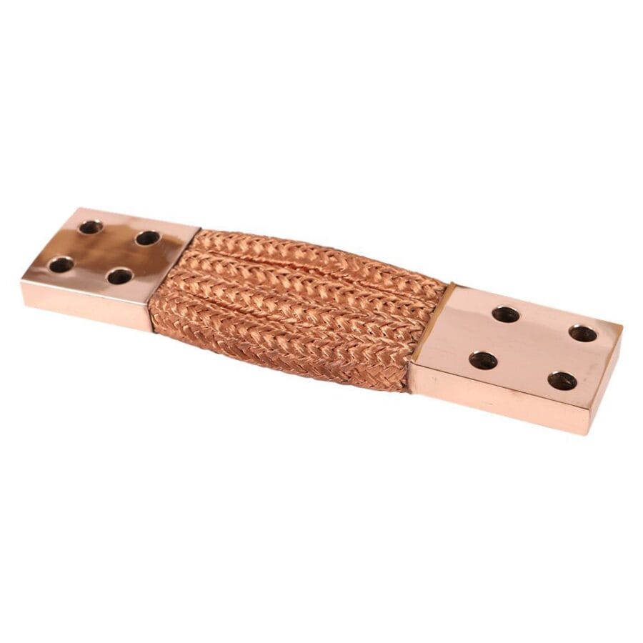
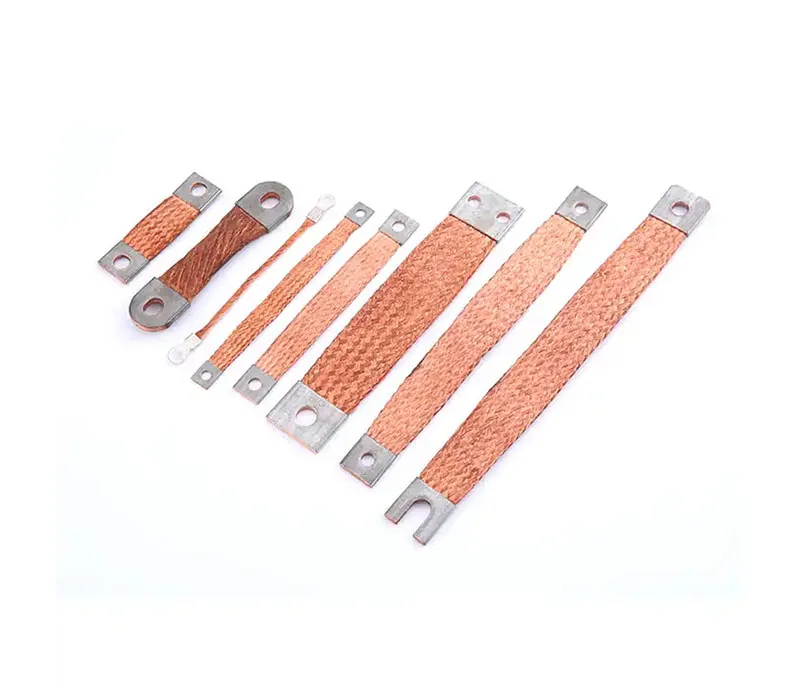
Surface Treatment and Joint Technology
Even a perfectly sized busbar can fail if the connections are poor. The contact surface is where resistance is highest. At JUMAI TECH, we emphasize that the “size” of the busbar extends to the contact overlap area.
Overlap Area Sizing
The general rule for bolting two busbars together is that the overlap length should be at least equal to the width of the busbar. For an mt copper busbar that is 50mm wide, the joint overlap should be at least 50mm. This ensures that current can transfer from one bar to the other without bottling up at the junction.
Furthermore, the clamping pressure applied by the bolts must be uniform. We utilize precision stamping to create perfectly flat contact surfaces, ensuring that when the bolts are torqued, the microscopic peaks and valleys of the copper mate effectively, maximizing the actual contact area.
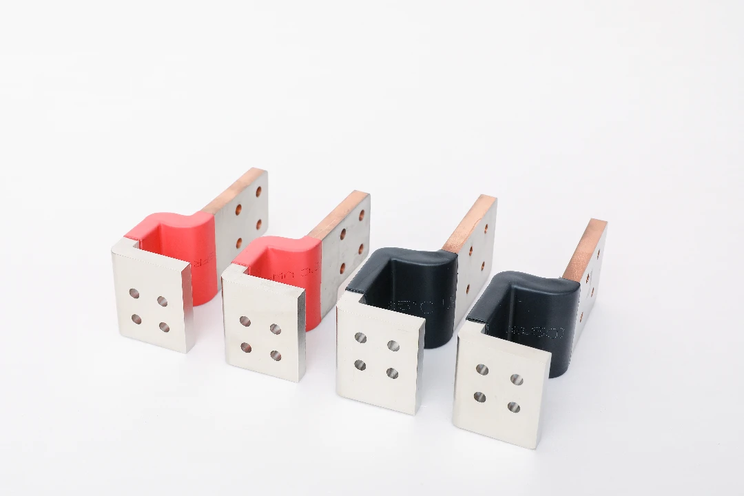
Plating Options: Tin vs. Silver
Raw copper oxidizes over time, forming copper oxide, which is a semiconductor and increases resistance. To maintain the ampacity rating of the mt copper busbar over decades, plating is essential.
- Tin Plating: Excellent for preventing corrosion and galvanic reaction with aluminum. It is cost-effective and suitable for most industrial applications up to $100^\circ C$.
- Silver Plating: Offers the highest conductivity and lowest contact resistance. It is preferred for high-efficiency, high-temperature applications.Choosing the right plating allows the busbar to run cooler at the joints, effectively validating the sizing calculations. You can read more about copper properties at the Copper Development Association.
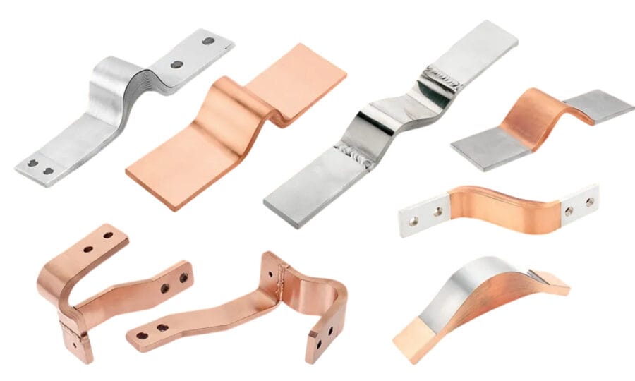
JUMAI TECH: Customization and Deep-Drawn Integration
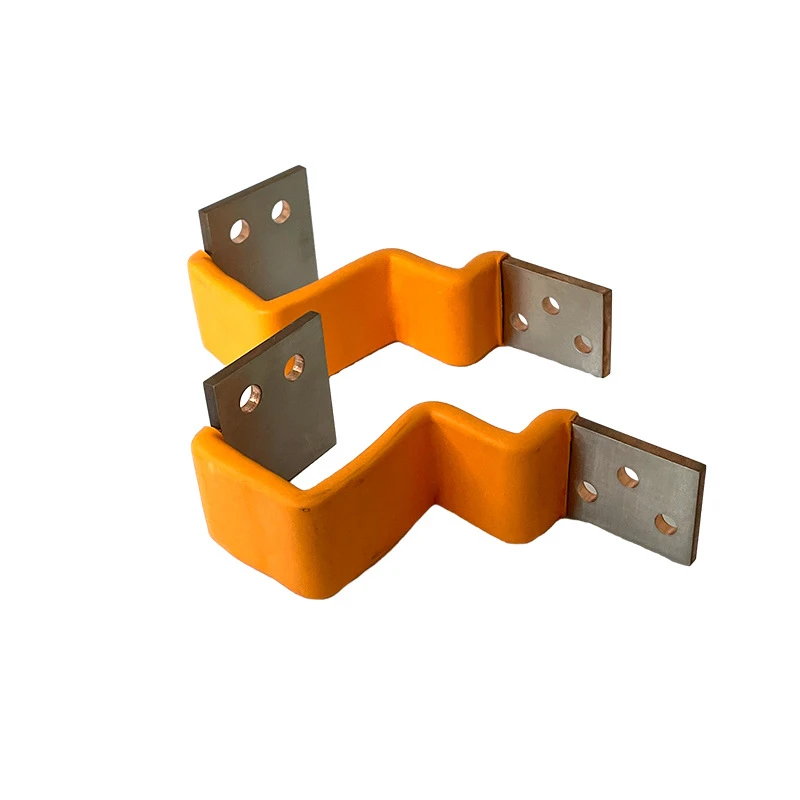
While standard flat bars are common, modern equipment often requires complex geometries to fit into tight spaces. This is where DeepDrawTech (JUMAI TECH) excels. Our capabilities in Deep-Drawn Components and Precision Stamping Dies allow us to manipulate mt copper busbar material into specific shapes without compromising its electrical integrity.
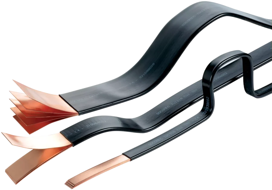
3D Busbar Bending and Forming
Sizing a busbar also involves calculating the bend radii. Bending copper too sharply creates stress fractures and thins the material at the outer edge of the bend, creating a “hot spot” of high resistance.
We utilize advanced CNC bending machines that automatically calculate the neutral axis of the mt copper busbar, ensuring that the cross-sectional area remains constant throughout the bend. This allows for complex, multi-plane routing inside switchgear cabinets where straight bars simply wouldn’t fit.
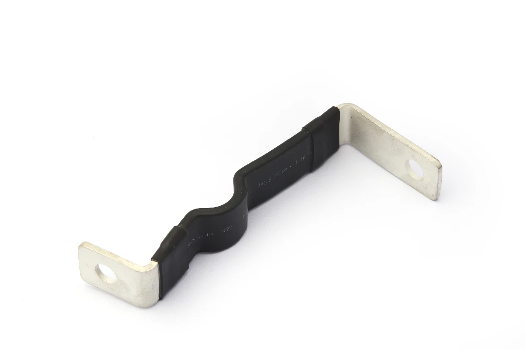
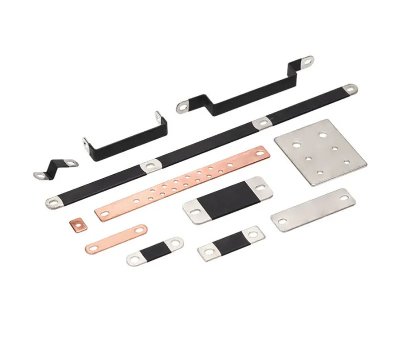
Integrated Deep-Drawn Features
In some advanced applications, such as battery interconnects for EVs or capacitor banks, traditional flat busbars are insufficient. We can integrate deep-drawn cups or dimples directly into the busbar. These features can serve as location guides for welding or as thermal expansion zones.
By combining our deep-drawing expertise with traditional busbar fabrication, we provide a hybrid solution that optimizes both electrical performance and mechanical assembly speed. This holistic approach ensures that the mt copper busbar is not just a conductor, but a multifunctional structural component of your device.
Comparing Copper vs. Aluminum Busbars
A common question we receive during the sizing phase is: “Why not use Aluminum?” While aluminum is lighter and cheaper, sizing an mt copper busbar offers distinct advantages that justify the investment for critical infrastructure.
Conductivity to Volume Ratio
Aluminum has approximately 61% of the conductivity of copper. To carry the same current as an mt copper busbar, an aluminum bar must be roughly 60% larger in cross-sectional area. In compact modern machinery, this extra volume is often unavailable. Copper allows for high power density, keeping enclosures small and footprint costs low.
Reliability and Creep
Aluminum suffers from “cold flow” or creep under pressure. Over time, the pressure in bolted joints relaxes, leading to loose connections and arcing. Copper is mechanically stable. Once torqued, an mt copper busbar joint remains tight. For mission-critical applications—such as hospital power systems or data centers—the reliability of copper is non-negotiable.
Best Practices for Installation and Maintenance
The lifecycle of an mt copper busbar depends heavily on how it is installed. Even correct sizing data cannot save a system installed with poor workmanship.
Torque Settings and Hardware
Using the correct grade of steel bolts (typically Grade 8.8) and Belleville washers (conical spring washers) is vital. The washers maintain tension on the joint even as the busbar expands and contracts with thermal cycles. We provide detailed torque specifications for all our custom busbar assemblies to ensure the contact pressure remains within the optimal range (typically 10-20 N/mm² of contact pressure).
Thermal Imaging Inspections
Once the system is operational, we recommend regular maintenance using thermal imaging cameras. A correctly sized mt copper busbar should show a uniform temperature gradient. If you see a bright “hot spot” at a joint, it indicates high resistance—likely due to a loose bolt or surface contamination—not necessarily an undersized bar. Regular monitoring validates that your sizing calculations hold true in the actual operating environment.
Conclusion: Partnering for Precision
Sizing an mt copper busbar is a multidimensional engineering challenge that balances electrical theory, thermal dynamics, mechanical stress, and economic constraints. It is not a place for guesswork. The risks of undersizing range from energy inefficiency to catastrophic fire hazards, while oversizing leads to uncompetitive product costs.
At JUMAI TECH, we do not just sell metal; we sell reliability. By leveraging our deep expertise in Precision Copper Busbars, Deep-Drawn Components, and Precision Stamping Dies, we assist our global clients in navigating these complexities. We ensure that every busbar we manufacture is optimized for its specific load, environment, and application.
Whether you are in the prototype phase or ready for mass production, our engineering team is ready to review your designs and suggest the optimal mt copper busbar configuration. Reliable power distribution starts with precision, and precision is the heartbeat of DeepDrawTech.