The landscape of global energy is undergoing a profound transformation. As the world rapidly transitions toward renewable energy sources, electrifies its transportation networks, and scales up high-density artificial intelligence data centers, the infrastructure that routes, manages, and distributes electrical power must evolve. At the very center of this electrical revolution is a highly engineered, deeply specialized component: the flexible copper busbar.
Gone are the days when simple, rigid blocks of metal were sufficient for industrial power distribution. Today’s applications demand components that can handle immense electrical loads while surviving high-vibration environments, extreme thermal cycling, and incredibly tight spatial constraints. At JUMAI, we have dedicated our engineering resources to mastering these challenges. Leveraging our extensive background in deep drawing dies and non-ferrous metal processing, we have refined the art and science of producing premium power connectors.
This comprehensive technical guide serves as an authoritative exploration into the manufacturing lifecycle of Flexible Copper Busbars. Designed for electrical engineers, procurement specialists, and system architects, this multi-part series will decode the metallurgy, the physics of electrical conduction, the precision manufacturing processes, and the rigorous testing protocols required to produce world-class industrial connectors.
The Paradigm Shift in Modern Electrical Distribution

To appreciate the manufacturing process, one must first understand the engineering imperatives driving the adoption of flexible laminated busbars over their traditional rigid counterparts. For decades, standard power distribution relied on solid copper or aluminum bars bolted together. While effective for static environments like legacy power substations, this approach presents catastrophic points of failure in dynamic, modern applications.
Consider the environment inside a modern megawatt-scale wind turbine nacelle or the battery compartment of a high-performance Electric Vehicle (EV). These environments are characterized by constant kinetic energy. A wind turbine generator is subject to relentless mechanical vibration, aerodynamic buffeting, and torsional stress. If rigid busbars are used to connect the generator to the transformer, the persistent vibration acts upon the bolted joints. Over time, these micro-movements loosen the hardware, increasing electrical contact resistance. According to fundamental Joule heating principles ($P = I^2R$), even a slight increase in resistance in a high-current system results in massive heat generation, eventually leading to thermal runaway or an electrical fire.
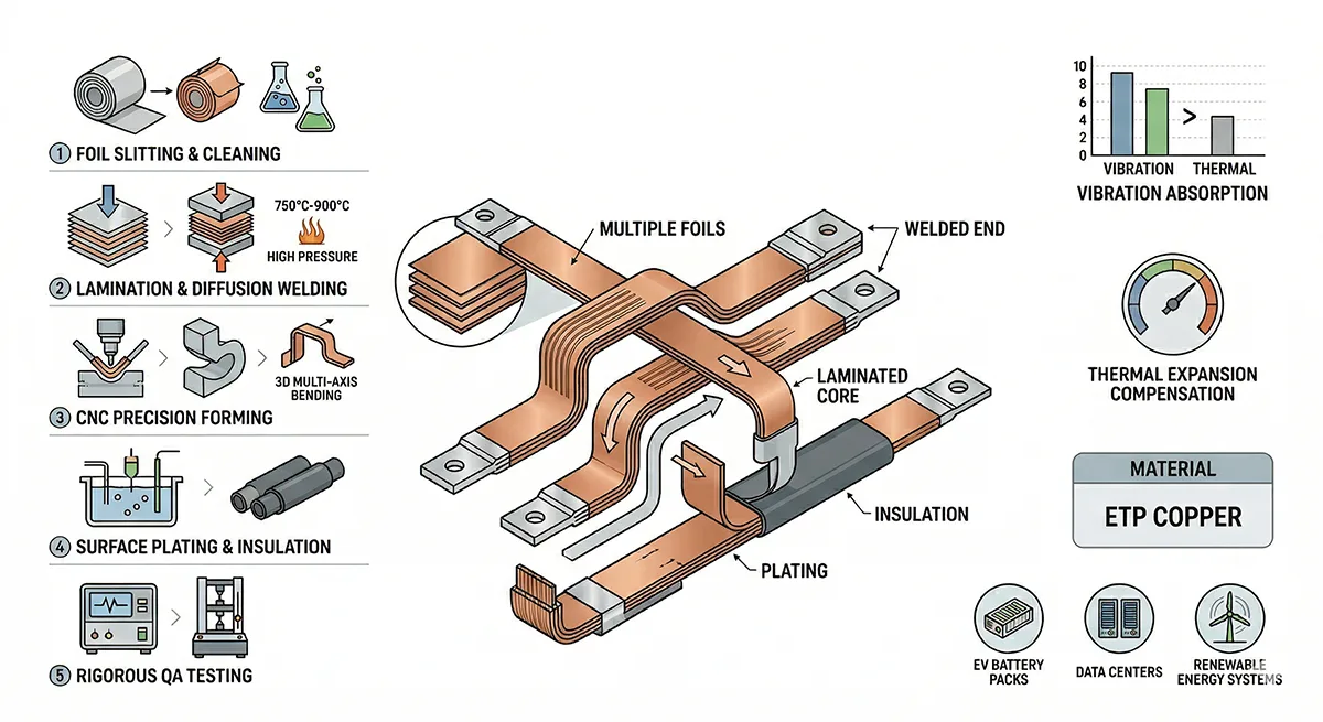
Flexible copper busbars eliminate this structural vulnerability. By fusing multiple thin layers of highly conductive copper at the connection terminals while leaving the mid-section unbonded, the component essentially acts as an electrical shock absorber. The unbonded foils can slide past one another microscopically, allowing the busbar to bend, twist, and absorb multi-directional kinetic energy without transferring that stress to the fragile electronic components it connects, such as Insulated-Gate Bipolar Transistors (IGBTs) or sensitive battery cell terminals.
Furthermore, thermal expansion poses a significant threat to rigid systems. As electrical current flows, conductors heat up and physically expand. When they power down, they contract. A solid metal bar constrained between two fixed points will inevitably warp, crack, or shear its mounting bolts under the immense force of thermal expansion. Flexible busbars possess inherent dimensional tolerance; their pre-engineered bends and laminated structure allow them to expand and contract gracefully, ensuring the structural integrity of the entire electrical architecture. For specialized configurations requiring unique geometric routing, system designers often rely on our JUMAI Soft & Rigid Copper Busbar Series to develop bespoke busbars that perfectly match their spatial constraints.
The Core Anatomy and Physics of Laminated Conduction
A premium flexible copper busbar is not merely a bundle of wires; it is a precisely engineered laminated structure designed to optimize electron flow under specific conditions. Understanding its anatomy requires a brief dive into the physics of electromagnetism, particularly how electrical current behaves in different environments.
Mitigating the Skin Effect in High-Frequency Systems
In Direct Current (DC) applications, such as standard battery storage, electrical current flows relatively uniformly through the entire cross-section of a conductor. However, the modern grid and industrial landscape rely heavily on Alternating Current (AC) and rapid high-frequency switching. In these scenarios, engineers must account for the “Skin Effect.”
The Skin Effect is a physical phenomenon where alternating electrical current tends to avoid the center of a solid conductor, flowing primarily near the outer surface, or “skin.” As the frequency of the AC current increases, the skin depth—the depth to which the current penetrates—becomes shallower.
If a solid, thick rigid copper bar is used in a high-frequency inverter or a modern busbar ampacity and heat dissipation guide, the center of the bar is essentially wasted space; it carries almost no current. The effective cross-sectional area is reduced, which drastically lowers the ampacity (current-carrying capacity) of the bar and causes it to overheat.
Flexible laminated busbars are structurally uniquely suited to combat the Skin Effect. Because they are composed of dozens or even hundreds of individual thin copper foils stacked together, the total surface area of the conductor is exponentially increased compared to a solid bar of the exact same outer dimensions. While the closely packed nature of the foils means they do not completely eliminate the skin effect, the laminated geometry drastically improves high-frequency current distribution, making them far more efficient for complex inverters, UPS systems, and renewable energy converters.
Ampacity and Heat Dissipation Dynamics
Beyond surface area, the laminated nature of these busbars provides superior thermal dynamics. Heat dissipation in an electrical cabinet is primarily achieved through convection and radiation. A flat, wide, flexible busbar has a vastly superior surface-area-to-volume ratio compared to a round cable or a thick solid square bar. This allows the component to shed thermal energy into the surrounding air much faster.
By keeping the operating temperature lower, the copper maintains a higher level of conductivity (since electrical resistance in metals increases with temperature). This creates a positive feedback loop of efficiency, which is why organizations like the Institute of Electrical and Electronics Engineers (IEEE) provide strict guidelines on the maximum allowable temperature rise for switchgear and control assemblies, standards that premium laminated busbars easily exceed.
Metallurgical Foundations: Selecting the Ultimate Copper Grade
The foundation of any high-performance electrical component lies in its raw material. No amount of advanced manufacturing can compensate for poor-quality metallurgy. In the production of premium flexible copper busbars, the purity of the copper dictates the ceiling of the product’s performance.
At JUMAI, the material sourcing protocol is uncompromising. The global market offers numerous grades of copper, but for high-power industrial applications, the acceptable spectrum narrows dramatically to two primary choices: Electrolytic Tough Pitch (ETP) Copper and Oxygen-Free (OF) Copper.
Trace Elements and Conductivity Impact
Even microscopic impurities in the copper matrix can disrupt the free flow of electrons, acting as “speed bumps” that cause resistance and generate heat. The industry standard for measuring this is the International Annealed Copper Standard (IACS). A perfectly pure piece of annealed copper is designated as 100% IACS.
To achieve the maximum possible energy transfer, we analyze the microstructural composition of our raw copper foils.
Table 1: Comparative Analysis of Industrial Electrical Copper Grades
| Material Designation | Global Standard Code | Copper Purity (Min %) | Oxygen Content (Max ppm) | Electrical Conductivity (% IACS) | Primary Application Environments |
|---|---|---|---|---|---|
| ETP Copper | C11000 / T2 / E-Cu58 | 99.90% | 400 ppm | 100% – 101% | Standard EV battery packs, solar inverters, general industrial switchgear. |
| Oxygen-Free Copper | C10200 / TU1 / OF-Cu | 99.95% | 10 ppm | 101% – 102.5% | High-vacuum systems, extreme high-frequency data centers, aerospace components. |
| Phosphorus-Deoxidized | C12200 / TP2 | 99.90% | (Phosphorus added) | ~85% | Used for plumbing or heat exchangers; Strictly rejected for premium electrical busbars due to low conductivity. |
As demonstrated in the data, the presence of oxygen is a critical differentiating factor. ETP Copper (C11000) contains a tiny amount of oxygen, intentionally left in during the smelting process to scavenge other impurities. For 90% of global industrial applications, ETP copper provides exceptional performance and perfect >100% IACS conductivity.
However, in ultra-demanding environments—such as high-vacuum systems or facilities subject to hydrogen embrittlement (where hydrogen gas reacts with the oxygen in the copper to form steam, causing the metal to blister and fracture)—Oxygen-Free Copper (C10200) is the absolute requirement. Because it is refined in a highly controlled, oxygen-free environment, it boasts unparalleled purity and marginally higher conductivity.
When clients consult with JUMAI for busbar copper material selection guide, our metallurgical engineers carefully evaluate the end-use environment to specify the exact grade of foil required, ensuring a perfect balance between ultimate performance and cost-efficiency.
Precision Foil Preparation and Surface Engineering
Once the premium copper coils arrive at the manufacturing facility, the transformation from raw material to an engineered component begins. The first phase involves slitting, shearing, and intensive surface preparation. This stage is deceptively critical; flaws introduced here will cascade through the rest of the manufacturing process, resulting in a compromised final product.
The Mechanics of Burr-Free Shearing
The raw copper arrives in massive, heavy coils. To create the flexible section of the busbar, these coils must be slit and sheared into highly precise, ultra-thin foils—typically ranging from 0.05mm to 0.30mm in thickness, depending on the required flexibility and current rating of the final product.
Standard industrial shearing machines act like a giant pair of scissors, forcing a steel blade through the metal. When cutting ultra-thin copper, standard shearing creates a microscopic problem known as a “burr”—a jagged, raised edge along the cut line.
If copper foils with micro-burrs are stacked together, the raised edges prevent the flat surfaces of the foils from making perfect, flush contact. These microscopic air gaps between the laminations severely compromise the subsequent welding process. Furthermore, in high-voltage applications, sharp burrs can act as points of electrical stress concentration, leading to corona discharge or premature breakdown of the dielectric insulation.
To prevent this, premium manufacturing relies on CNC-controlled, high-speed rotary slitting and precision stamping utilizing proprietary die designs. JUMAI’s deep expertise in stamping die basics and precision forming allows us to design ultra-tight tolerance tooling in-house. Our precision tooling ensures that every single foil is cut with a perfectly sheer, 90-degree edge, entirely eliminating edge distortion and burrs. This guarantees a mathematically perfect stack when hundreds of foils are layered together.
The Chemistry of Oxidation Removal and Degreasing
Copper is a highly reactive metal. When exposed to ambient air, it immediately begins to react with oxygen, forming a microscopic layer of cuprous oxide ($Cu_2O$). Additionally, during the milling and shearing processes, trace amounts of machine lubricating oils and airborne particulates inevitably settle on the foil surfaces.
These contaminants are the mortal enemies of the diffusion welding process. Molecular diffusion requires pure copper atoms to physically touch and share electron clouds. A barrier of oil or oxidation, even one that is only a few molecules thick, will prevent bonding and lead to delamination (the foils peeling apart) in the final product.
Therefore, prior to stacking, the individual cut foils must undergo a rigorous, multi-stage chemical and mechanical cleaning protocol:
- Ultrasonic Degreasing Bath: The foils are submerged in an eco-friendly, heated alkaline solution. High-frequency ultrasonic transducers bombard the bath, creating millions of microscopic cavitation bubbles. When these bubbles collapse against the copper surface, they release tiny shockwaves that scrub away oils and deep-seated particulates without scratching the soft metal.
- Deoxidizing Acid Etch: The foils are briefly passed through a mild, highly controlled acid solution to chemically strip away any existing oxidation layers, exposing the raw, highly reactive pure copper lattice beneath.
- Deionized Water Rinse: Standard tap water contains minerals (like calcium and magnesium) that would leave a conductive residue on the copper. The foils are thoroughly rinsed using pure deionized (DI) water to remove all traces of the etching chemicals.
- Flash Drying: The wet, highly reactive pure copper is immediately passed through high-velocity hot air tunnels to dry instantly. If water is allowed to evaporate slowly, it will create water spots and trigger immediate re-oxidation.
Only after this meticulous preparation are the pristine copper foils ready to be stacked and permanently fused together.
The Superiority of Polymer Diffusion Welding

In standard electrical manufacturing, joining metals typically involves introducing a third material (like solder) or melting the parent metals together (like arc welding). Both of these traditional methods are completely unacceptable for premium flexible copper busbars.
Why? Introducing a filler alloy, such as tin-lead or silver solder, fundamentally alters the electrical resistance at the joint. These filler metals have lower conductivity than pure C11000 copper. When thousands of amps pass through this bottleneck, it generates massive localized heat. Conversely, traditional arc welding melts the copper entirely (exceeding its 1085°C melting point). This destroys the laminated structure, turning the flexible section into a brittle, solid, and highly oxidized lump of metal.
To solve this, JUMAI relies exclusively on Polymer Diffusion Welding (also referred to as Thermal Press Welding or Solid-State Diffusion Bonding).
The Physics of Solid-State Bonding
Diffusion welding operates on the principle of atomic diffusion at elevated temperatures and extreme pressures. The pre-cleaned stack of copper foils is clamped firmly between specialized, highly conductive electrodes (typically machined from high-density graphite or custom refractory alloys).
A massive surge of localized electrical current is passed through the electrodes, heating the clamped ends of the copper stack to a precise sub-melting temperature—usually between 750°C and 900°C. Simultaneously, industrial hydraulic rams apply immense mechanical pressure (up to 30 MPa) to the stack.
Under this exact combination of heat and pressure, the copper atoms at the microscopic interfaces of the foils become highly energized. Without ever turning into a liquid, the atoms migrate (diffuse) across the boundaries of the individual foils. The layers literally interlock on a molecular level, becoming a single, homogeneous, solid block of pure copper.
Because there is no melting and no filler metal introduced, the welded connection maintains the exact same >100% IACS conductivity as the raw foil. The American Welding Society (AWS) recognizes solid-state welding as one of the most reliable methods for joining highly conductive non-ferrous metals without metallurgical degradation.
Essential Parameters for Perfect Diffusion Welds
Achieving a flawless diffusion weld is an exacting science. If the temperature is too low or the dwell time too short, the center foils will not bond, leading to catastrophic delamination under stress. If the temperature is too high, the copper oxidizes rapidly and becomes brittle.
Below is a baseline matrix of the controlled parameters utilized in our automated welding centers.
Table 2: Baseline Diffusion Welding Parameters for C11000 Copper Foils
| Individual Foil Thickness | Total Welded Stack Thickness | Hydraulic Pressure Applied | Optimum Temp Range | Heating Dwell Time |
|---|---|---|---|---|
| 0.10 mm | 10.0 mm (100 layers) | 15.0 – 18.0 MPa | 780°C – 820°C | 12 – 16 Seconds |
| 0.20 mm | 15.0 mm (75 layers) | 18.0 – 22.0 MPa | 800°C – 850°C | 18 – 24 Seconds |
| 0.30 mm | 20.0 mm (67 layers) | 22.0 – 26.0 MPa | 830°C – 880°C | 25 – 35 Seconds |
Data Note: These parameters are dynamic. Ambient humidity, atmospheric pressure, and the specific geometry of the custom busbar require micro-adjustments managed by real-time CNC monitoring systems.
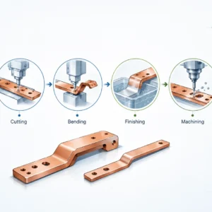
Post-Weld Precision Machining
Once the diffusion process is complete, the ends of the flexible copper busbars are indistinguishable from a solid, forged block of copper. This structural rigidity at the terminals is crucial for the next phase: precision machining.
While standard, straight-cut rectangular busbars are common, modern engineering often requires complex terminal geometries. In high-density battery storage or custom JUMAI Soft & Rigid Copper Busbar Series, the busbar must navigate around cooling pipes, structural chassis elements, and tightly packed relays.
This requires milling out specific shapes, drilling precise mounting holes, and sometimes creating counter-sunk connection points. Because JUMAI possesses an extensive, in-house ecosystem for JUMAI Soft & Rigid Copper Busbar Series, we hold a distinct advantage here. We not only machine the final busbars but also design the custom stamping and pressing tools required to form specialized mounting brackets or complex 3D profiles before the welding stage even occurs. This vertical integration drastically reduces structural stress during the final CNC milling process, ensuring geometric tolerances of ±0.05mm.
Surface Engineering: Mitigating Contact Resistance via Plating
A perfectly welded and machined copper busbar is highly conductive, but bare copper has a fatal flaw in the real world: it oxidizes rapidly.
When bare copper is exposed to oxygen, humidity, or industrial pollutants (like sulfur), it develops a layer of copper oxide or copper sulfide (tarnish). These compounds are electrical insulators. If a bare copper busbar is bolted to a battery terminal, this invisible insulating layer dramatically increases the Contact Resistance at the joint.
To guarantee low-resistance, maintenance-free connections over a 20-year operational lifespan, the mounting terminals (and often the entire busbar) must undergo electrolytic surface plating.
Industrial Plating Standards and Applications
- Tin Plating (The Industry Standard): Tin is highly resistant to oxidation and provides excellent environmental protection. It is relatively soft, meaning that when the busbar is bolted down, the tin layer microscopically deforms, filling in tiny surface imperfections between the busbar and the terminal, creating an air-tight, low-resistance seal. Tin-plated flexible copper busbars are the standard for EV battery packs, solar inverters, and general switchgear.
- Silver Plating (The High-Performance Tier):Silver possesses the highest electrical and thermal conductivity of any metal. While more expensive, silver plating is mandatory in ultra-high-current applications where absolutely zero contact resistance can be tolerated. Silver-plated braided busbar power solutions and laminated busbars are heavily utilized in military radar systems, aerospace grids, and AI-driven data center server racks.
- Nickel Plating (The Extreme Environment Choice):Nickel is harder and handles much higher operating temperatures than tin or silver. It is deployed in heavy-duty industrial furnaces, chemical processing plants, and environments where highly corrosive gases are present.
Advanced Dielectric Insulation Systems
Safety is paramount. Operating at voltages up to 1500V DC in modern solar arrays or 800V in electric vehicles, a bare busbar is a lethal hazard and a massive short-circuit risk. Premium flexible copper busbars must be enveloped in robust, highly dielectric (electrically insulating) materials that can move naturally with the flexible copper foils without tearing or degrading.
The choice of insulation is dictated by the operating environment, the required voltage rating, and the physical shape of the busbar. Compliance with rigorous global safety standards, such as those established by Underwriters Laboratories (UL), is strictly enforced during this phase.
1. Cross-Linked Polyolefin Heat Shrink Tubing
This is the most widely utilized insulation in the EV and telecommunications sectors. The busbar is slipped into an extruded tube of radiation-cross-linked polyolefin. It then passes through a thermal tunnel. Upon exposure to heat (usually around 120°C), the tubing shrinks tightly around the metal, creating a seamless, conformal, and highly flexible jacket.
Polyolefin is favored because it is halogen-free (meaning it doesn’t release toxic gases if burned), highly resistant to automotive fluids (coolants, oils), and offers a staggering dielectric strength of up to 25 kV/mm.
2. Extruded PVC (Polyvinyl Chloride)
For more standard industrial applications where extreme temperature fluctuations are not a primary concern, flexible busbars can be dipped or extruded directly with a thick layer of high-grade PVC. PVC provides excellent mechanical protection against abrasion and physical impacts, making it ideal for heavy machinery and rigid busbar vs cable distribution comparison.
3. Fluidized Bed Epoxy Powder Coating
When engineers design incredibly complex, multi-axis bent busbars, traditional heat shrink tubing cannot navigate the tight corners without wrinkling or leaving dangerous air gaps. In these scenarios, epoxy powder coating is the superior solution.
The machined busbar is heated to approximately 200°C and then dipped into a fluidized bed—a tank where fine dielectric epoxy powder is suspended in a cloud of compressed air. When the suspended powder touches the hot metal, it instantly melts and flows into every microscopic crevice, curing into a hard, smooth, and perfectly uniform insulating shell. While epoxy is more rigid than PVC, it provides unmatched thermal resilience and dielectric protection for complex geometries.
Table 3: Comparative Analysis of Busbar Insulation Technologies
| Insulation Material | Continuous Operating Temp | Dielectric Strength | Flexibility Retention | Ideal Application Sector |
|---|---|---|---|---|
| Polyolefin Heat Shrink | -55°C to +125°C | ~ 20 – 25 kV/mm | Excellent | High-Voltage EV Packs, Telephony |
| Extruded PVC | -40°C to +105°C | ~ 15 kV/mm | Very Good | General Switchgear, Low-Voltage |
| Epoxy Powder Coat | -40°C to +130°C | ~ 25 – 30 kV/mm | Rigid (applied post-bending) | Complex 3D Routing, Spatial Constraints |
With the bonding, machining, plating, and insulation processes complete, the flexible copper busbar is fundamentally finished. However, it cannot be deployed into critical infrastructure without passing through a gauntlet of destructive and non-destructive quality assurance testing.
Advanced Manufacturing: The Production Process of Premium Flexible Copper Busbars [Part 3]
While the chemical purification, molecular diffusion welding, and dielectric insulation stages establish the electrical and safety baselines of the component, the physical integration of the busbar into its final operating environment requires masterful mechanical engineering. Modern electrical architectures are rarely spacious. From the densely packed chassis of an electric vehicle to the ultra-compressed server racks of an artificial intelligence data center, power routing must conform to strict spatial limitations.
This brings us to the highly specialized discipline of multi-axis shaping and the exhaustive quality assurance protocols required before any component leaves the JUMAI manufacturing facility.
The Art and Science of Multi-Axis 3D Bending

Standard rigid metal bars are relatively straightforward to bend. Engineers calculate the yield strength of the material, determine the bend allowance (K-factor), and use heavy hydraulic press brakes to force the metal into shape.
Bending Flexible Copper Busbars, however, is an entirely different mechanical challenge. Because the core of the busbar consists of unbonded, independent copper foils wrapped in a dielectric jacket, applying standard press brake techniques would be disastrous.
The Mechanics of Foil Slippage
When a laminated busbar is bent, the foils on the outer radius of the bend must travel a longer distance than the foils on the inner radius. To accommodate this difference without tearing the metal, the individual copper foils must be allowed to microscopically slide past one another within the insulated jacket.
If a bend is forced too quickly or with improper tooling, several catastrophic failures can occur:
- Insulation Rupture: The inner radius can pinch and slice through the heat shrink tubing or PVC extrusion, destroying the dielectric barrier.
- Foil Warping: The copper foils can buckle and fan out uncontrollably, creating a swollen area that will not fit into the designated spatial envelope.
- Weld Stress: If the bend is too close to the diffusion-welded terminal, the mechanical force can leverage against the molecular bond, potentially causing micro-fractures in the solid end block.
To prevent this, JUMAI utilizes proprietary, CNC-controlled servomotor bending machines specifically designed for laminated profiles. These machines use custom-machined urethane or polished steel rollers that gently coax the busbar into complex, three-dimensional (3D) shapes. This controlled deformation allows the foils to fan symmetrically at the apex of the bend without compromising the integrity of the insulation or the welded terminals.
This capability is the cornerstone of our JUMAI Soft & Rigid Copper Busbar Series, allowing us to deliver power connectors that snake flawlessly around cooling lines, structural pillars, and sensitive electronic relays.
Uncompromising Quality Assurance Protocols
In the high-voltage industrial sector, component failure is unacceptable. A micro-fracture in a busbar inside a megawatt solar inverter can trigger an arc flash, leading to catastrophic equipment destruction and extreme safety hazards. Therefore, the final phase of manufacturing is entirely dedicated to destructive and non-destructive Quality Assurance (QA) testing.
Our testing protocols are aligned with the stringent frameworks established by global standardization bodies, including the National Electrical Manufacturers Association (NEMA) and the International Electrotechnical Commission (IEC).
1. Micro-Ohm Contact Resistance Testing
The primary function of a busbar is to conduct electricity with the lowest possible resistance. Even a flawless-looking diffusion weld might harbor microscopic internal voids. We utilize highly sensitive four-wire micro-ohmmeters to measure the voltage drop across the welded terminals.
The resistance must exactly match the theoretical resistance of a solid piece of C11000 copper of the same dimensions. If the resistance spikes by even a fraction of a micro-ohm, it indicates a compromised weld, and the batch is immediately quarantined.
2. Destructive Tensile and Shear Strength Testing
To verify the molecular integrity of the diffusion process, random samples from every production run are subjected to extreme physical stress in hydraulic pull testers.
A perfectly executed diffusion weld will exhibit a tensile strength equivalent to the parent copper. In successful destructive tests, the raw copper foil itself will stretch and tear before the weld joint separates. This proves unequivocally that the molecular bond is stronger than the raw material.
3. High-Voltage Dielectric Withstand (Hipot) Testing
The insulation system is just as critical as the conductive core. To ensure there are no pinholes, microscopic tears, or weaknesses in the heat shrink or epoxy coating, the busbar undergoes Dielectric Withstand Testing, commonly known as Hipot testing.
A massive voltage spike (often between 3,000V and 10,000V AC/DC, depending on the component’s rating) is applied between the copper core and the outer surface of the insulation. If the testing equipment detects any leakage current passing through the dielectric jacket, the insulation has failed. This guarantees absolute safety for technicians and automated assembly lines.
4. Extreme Thermal Cycling and Accelerated Aging
Electrical components in renewable energy and automotive applications face brutal environments. A busbar in an EV might experience -30°C in winter and surge to +105°C during rapid charging.
Because copper and polymer insulation have different Coefficients of Thermal Expansion (CTE), they expand and contract at different rates. Over time, this mismatch can cause the insulation to become brittle and crack. At JUMAI, sample busbars are placed in environmental test chambers, where they are subjected to hundreds of hours of rapid, extreme temperature cycling (-40°C to +125°C). Following this accelerated aging, the Hipot and conductivity tests are repeated to ensure long-term operational resilience.
Table 4: Summary of Critical QA Thresholds for Premium Busbars
| Test Parameter | Testing Equipment / Method | Minimum Acceptable Threshold | Purpose of Test |
|---|---|---|---|
| Weld Resistance | Four-Wire Micro-Ohmmeter | ≤ 105% of solid copper baseline | Guarantees zero localized heating at terminals. |
| Tensile Strength | Hydraulic Pull Tester | Foil failure precedes weld failure | Validates molecular diffusion bond integrity. |
| Dielectric Strength | Hipot Tester | Zero leakage at 3kV – 10kV (varies) | Ensures absolute high-voltage isolation. |
| Thermal Resilience | Environmental Chamber | 500+ cycles (-40°C to +125°C) | Validates 20-year lifespan under extreme conditions. |
Industrial Applications Driving the Market
The intense engineering, metallurgical science, and rigorous testing we have explored culminate in components that power the most critical sectors of the modern global economy. The transition from rigid bars to flexible copper busbars is being aggressively driven by three primary industries.
The 800V Electric Vehicle (EV) Architecture
The automotive industry is in the midst of a massive technological arms race. To reduce charging times and increase vehicle range, manufacturers are abandoning standard 400V battery architectures in favor of 800V and even 1000V systems.
At these voltages, managing current efficiently within the incredibly tight confines of a vehicle chassis is a monumental challenge. Flexible copper busbars are the vital arteries of these vehicles. They route power from the massive battery packs to the inverters and electric motors, absorbing the constant, high-frequency kinetic vibration of the road. Their flat, wide profile allows engineers to keep battery packs exceptionally low to the ground, improving vehicle aerodynamics and handling while safely dissipating extreme thermal loads during rapid DC fast-charging cycles.
High-Density AI Data Centers
The explosion of Artificial Intelligence (AI) and machine learning has fundamentally rewritten the rules of data center power management. Legacy data centers consumed perhaps 5kW to 10kW of power per server rack. Today, liquid-cooled racks housing thousands of specialized AI processing units can draw upwards of 100kW per rack.
Routing this much amperage into such a dense, restricted space using traditional wiring is physically impossible; the cables would be too thick to bend and would generate dangerous levels of heat. High-performance JUMAI Soft & Rigid Copper Busbar Series, relying heavily on custom-routed flexible and braided copper busbars, are the only viable method to deliver stable, high-amperage power directly to the server blades while minimizing the high-frequency Skin Effect.
Renewable Energy and Grid Scale Storage
As the world moves away from fossil fuels, the grid relies increasingly on intermittent energy sources like solar and wind. This requires massive, grid-scale Energy Storage Systems (ESS)—essentially building-sized batteries.
Inside these ESS containers, thousands of individual lithium-ion or LiFePO4 battery cells must be chained together. Flexible copper busbars act as the bridge between the battery modules and the massive central inverters. They are uniquely capable of handling the continuous, heavy DC loads while absorbing the thermal expansion that naturally occurs as the massive battery banks charge during the day and discharge power back into the municipal grid at night.
Building the Conductive Infrastructure of Tomorrow
The production of a premium flexible copper busbar is a masterclass in modern manufacturing. It requires a profound understanding of metallurgy, thermodynamics, molecular physics, and advanced CNC machining. It is not merely a piece of hardware; it is an engineered solution to the complex challenges of high-voltage power distribution.
As global power grids continue to modernize, as transportation becomes universally electric, and as the computational demands of the digital economy skyrocket, the reliance on ultra-reliable, high-performance power connectors will only intensify. Substandard connections result in lost energy, compromised safety, and catastrophic system failures.
At JUMAI, we do not just manufacture components; we engineer certainty. From the deep drawing of specialized custom dies to the final high-voltage Hipot test, our fully integrated manufacturing ecosystem ensures that every product we deliver meets the absolute highest standards of the industry.
Whether you are designing the next generation of electric vehicles, engineering a megawatt solar array, or outfitting a hyperscale data center, your power architecture is only as strong as its connections. To explore our full range of capabilities, view detailed material specifications, or initiate a consultation for your specific engineering needs, visit the JUMAI Soft & Rigid Copper Busbar Series. Partner with us, and together, we will build the highly conductive, hyper-efficient infrastructure of tomorrow.
Advanced Thermal Dynamics and Ampacity Optimization

A flexible copper busbar is not merely a passive piece of hardware; during operation, it acts as an active thermal engine. To engineer a reliable power distribution system, one must deeply understand the relationship between electrical current, electrical resistance, and heat generation. This brings us to the critical concept of ampacity—the maximum amount of continuous current a conductor can carry before exceeding its thermal limits and sustaining immediate or progressive degradation.
At JUMAI, we frequently consult with engineers who initially underestimate the thermal complexities of enclosed high-current systems. Accurately determining ampacity goes far beyond basic cross-sectional area calculations; it requires a holistic evaluation of the busbar’s thermal environment. For a foundational dive into the specific math behind these metrics, you can refer to our comprehensive Copper Busbar Ampacity Calculation Guide.
The Physics of Heat Dissipation in Laminated Systems
When electrical current passes through the laminated copper foils, the inherent (albeit low) resistance of the C11000 ETP copper causes a portion of the electrical energy to be converted into heat energy. This is governed by Joule’s Law ($P = I^2R$). The higher the current ($I$), the exponentially greater the heat ($P$) generated.
To prevent the busbar from exceeding the temperature ratings of its dielectric insulation (for instance, the 125°C limit of cross-linked polyolefin heat shrink), the busbar must shed this heat into its surroundings at a rate equal to or faster than the heat being generated. This is achieved through three thermodynamic mechanisms:
- Conduction: Heat travels from the hottest part of the busbar (usually the center of the flexible section) toward the cooler, solid-welded terminals. The heat is then transferred directly into the heavy switchgear components or relay blocks to which the busbar is bolted.
- Convection (The Primary Cooling Mechanism): As the surface of the busbar heats up, it warms the adjacent air. Because hot air is less dense, it rises, pulling cooler air across the surface of the busbar. This natural convection cycle is why the massive surface area of a flexible laminated busbar is so advantageous. As detailed in our studies regarding busbar copper materials for low-resistance paths, a wide, flat profile drastically outperforms a round cable of the equivalent cross-section in natural convection cooling. In high-density applications, engineers will introduce forced convection (cooling fans) to multiply this effect.
- Radiation: The busbar constantly emits thermal energy as infrared radiation. Interestingly, the color and finish of the busbar significantly affect its emissivity (its ability to radiate heat). A bare, shiny copper busbar has very low emissivity. However, when the busbar is coated in a matte black PVC or black heat shrink tubing, its emissivity rating skyrockets, allowing it to shed radiant heat much more effectively.
Proximity Effects and System-Level De-rating
A common engineering pitfall is testing a single flexible copper busbar in open air, achieving a high ampacity rating, and then installing three of those busbars side-by-side in a cramped, unventilated inverter cabinet.
When busbars carrying Alternating Current (AC) are placed in close physical proximity, their electromagnetic fields interact. This interaction forces the current to crowd into even smaller areas of the copper foils, artificially increasing the localized resistance. This is known as the Proximity Effect.
Furthermore, if three busbars are stacked closely together, the middle busbar is “starved” of cooling air and is simultaneously absorbing the radiated heat from the two busbars next to it. Therefore, when designing multi-phase systems, engineers must apply strict “de-rating factors” to their ampacity calculations to account for enclosed spaces and proximity.
Table 5: Estimated Ampacity De-rating Factors for Enclosed Busbar Installations
| Installation Condition | Ambient Air Temp | Spacing Between Phases | De-rating Multiplier |
|---|---|---|---|
| Open Air (Free Convection) | 35°C | > 2x Busbar Width | 1.00 (Baseline) |
| Standard Vented Enclosure | 45°C | 1x Busbar Width | 0.85 |
| Sealed/Unvented Cabinet | 55°C | 1x Busbar Width | 0.70 |
| High-Density Packed Box | 65°C | < 0.5x Busbar Width | 0.50 – 0.60 |
Data source: Derived from standard IEC 61439 thermal testing parameters for low-voltage switchgear assemblies. Precise multipliers must be verified through prototype thermal testing.
Environmental Resilience and Installation Integrity
The most flawlessly manufactured flexible copper busbar can still fail in the field if installation best practices are ignored or if the surrounding environmental hazards are not properly mitigated. The connection interface—where the diffusion-welded terminal meets the equipment—is the most vulnerable point in the entire power distribution chain.
The Mechanics of Clamping Force
When bolting a busbar terminal to an electrical contact, the goal is to create an air-tight, cold-welded joint. Metal surfaces, no matter how smoothly machined, are microscopically rough. They consist of microscopic peaks and valleys. When two metal surfaces are placed together without pressure, electrical current can only flow through the few peaks that actually touch. This creates high contact resistance.
By applying heavy, calibrated clamping force (measured in Newton-meters of torque), these microscopic peaks are crushed, drastically increasing the true contact area. However, copper is a relatively soft metal. If an installer applies too much torque without using proper load-spreading hardware (like heavy-duty Belleville washers), the copper terminal will “creep” or permanently deform under the bolt head, eventually causing the connection to loosen over time.
Mitigating Galvanic Corrosion in Dissimilar Metals
In many grid-scale storage setups, engineers must connect our Soft & Rigid Copper Busbar Series to aluminum terminals on battery cells or transformers. Connecting bare copper directly to bare aluminum in the presence of humidity creates a microscopic battery.
This process, known as galvanic corrosion, causes the aluminum (the more anodic metal) to rapidly oxidize and degrade, forming aluminum oxide—a powerful electrical insulator. Within months, the joint will overheat and fail.
To prevent this, the copper terminals must be appropriately surface-treated. Tin plating is the standard defensive barrier. Tin sits between copper and aluminum on the galvanic scale, neutralizing the chemical reaction. In extreme marine or high-humidity industrial environments, specialized bi-metallic transition plates (copper explosively welded to aluminum) are used as an intermediary layer.
Vibration Management: The Role of Braided Alternatives
While flexible laminated busbars are exceptional at handling thermal expansion and single-axis vibration, some extreme applications—such as the massive transformers on high-speed rail networks or heavy earth-moving equipment—experience severe, unpredictable, multi-axis shock forces.
In these specific scenarios, laminated foils might experience fatigue if subjected to extreme torsional (twisting) forces. Engineers will often switch to, or combine laminates with, highly woven copper braids. To understand the specific engineering use-cases where braided designs outperform laminated designs, you can explore our technical brief on What a Braided Busbar is Used For. Braids provide 360-degree flexibility, acting as ultimate kinetic isolators for fragile ceramic transformer bushings.
The Strategic Advantage of Vertically Integrated Manufacturing
Producing a high-quality flexible copper busbar is fundamentally a precision metal forming operation. Many suppliers in the electrical industry purchase their copper foils from one vendor, have the terminals stamped by a secondary machine shop, outsource the diffusion welding to a third party, and apply the insulation themselves.
This fragmented supply chain introduces massive risks regarding quality control, dimensional tolerance stacking, and extended lead times. JUMAI’s fundamental differentiator in the global market is our absolute vertical integration.
As detailed in our Stamping Die Basics guide, the “engine” behind consistent, high-volume production is the tooling. Because our engineering teams design, CNC-mill, and maintain the actual deep-drawing dies and precision stamping tools in-house, we hold complete control over the dimensional integrity of every busbar we produce.
If a client requires a customized, complex bend radius for a new EV battery chassis, we do not have to wait weeks for an external toolmaker. We adjust the tooling internally, run the first-off samples, verify the burr-free edges, and move immediately into high-volume diffusion welding. This integration ensures that the final assembly fits perfectly into the client’s system with zero forced resistance, mitigating thermal risks from day one.
For engineers evaluating the structural integrity of their current power distribution architecture, or for procurement teams looking to optimize their supply chain with a vertically integrated manufacturer, we invite you to connect with our technical teams. You can review our full corporate capabilities and history via the About JUMAI page, or reach out directly through our Contact portal to request custom prototypes and engineering support.