High-current systems are becoming smaller, denser, and more sensitive to heat. Electric vehicles, battery energy storage systems, data centers, industrial switchgear, UPS cabinets, charging infrastructure, and renewable energy converters all need power paths that are compact, repeatable, electrically efficient, and safe to assemble. This is where Rigid Busbars remain one of the most practical conductor solutions.
A copper rigid busbar may look simple from the outside: a flat or formed piece of copper with holes, bends, plating, insulation, or terminal windows. In reality, it is a functional electrical, thermal, mechanical, and manufacturing component. Its performance depends on copper grade, cross-sectional area, surface finish, plating, insulation, hole quality, flatness, bend accuracy, contact pressure, short-circuit capability, and the real operating environment inside the equipment.
At JUMAI, we work with global customers on custom copper busbars, including soft copper busbars, rigid copper busbars, and braided copper busbars. Our role is not only to supply a piece of copper. We help buyers and engineers connect the practical questions behind the drawing: What current must the part carry? What temperature rise is acceptable? Which copper grade is appropriate? Should the contact area be tin plated, nickel plated, silver plated, or left bare? How will the part be assembled, inspected, packed, and repeated in production?
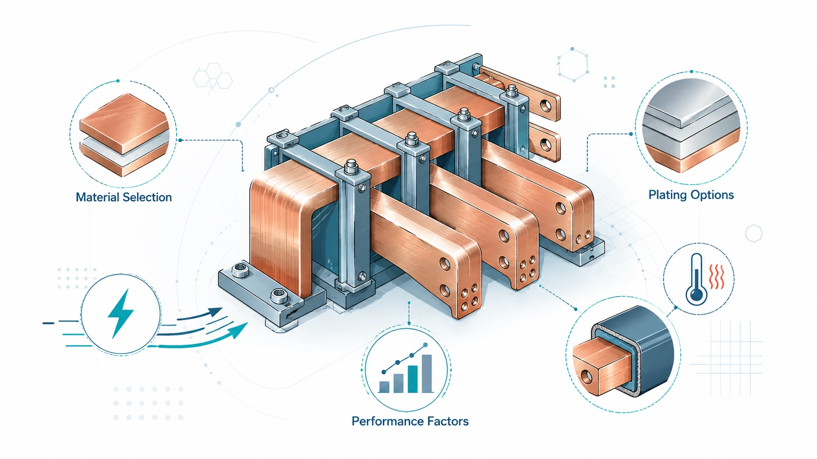
This guide explains how buyers, electrical engineers, mechanical engineers, and procurement teams can make better decisions when specifying copper rigid busbars. The focus is practical: material selection, plating options, and the performance factors that usually decide whether a rigid busbar becomes a reliable part or a hidden risk in the system.
Table of Contents
Why copper rigid busbars still matter in modern power systems
Power distribution design has changed significantly in the past decade. Many systems now run at higher current, higher power density, and tighter packaging than older cabinet designs. Cables are still useful, and flexible or braided copper conductors are essential where movement must be absorbed. But for fixed high-current paths, rigid copper busbars are still difficult to replace.
A rigid busbar gives the designer a defined geometry. The current path, bend position, terminal pad, mounting hole, insulation window, and clearance envelope can be controlled in CAD and repeated in production. Compared with cable routing, this can reduce assembly variation, make torque access clearer, simplify inspection, and improve heat dissipation. In high-volume programs, repeatability is not a small benefit. It can reduce training time, prevent operator mistakes, and make electrical validation easier.
Industry demand also supports the need for better busbar design. The International Energy Agency reported that global electric car sales topped 17 million in 2024, while its Global EV Outlook 2025 expected sales to exceed 20 million in 2025. Energy storage is expanding even faster in power-system terms: IEA’s Global Energy Review 2026 reported 108 GW of new battery storage capacity deployed worldwide in 2025, 40% more than in 2024, with around 80% of that new capacity being utility-scale. Data centers are another major driver. The U.S. Department of Energy reported that U.S. data center electricity use grew from 58 TWh in 2014 to 176 TWh in 2023 and could reach 325-580 TWh by 2028. IEA’s Energy and AI analysis projected global data center electricity consumption could reach around 945 TWh by 2030.
These numbers do not mean every high-current system should use more copper without analysis. They mean electrical interconnection is becoming more important commercially. A small increase in joint resistance, a poor plating decision, or an under-specified insulation window can become expensive when it is repeated across battery modules, rack cabinets, inverter assemblies, switchgear panels, or AI power infrastructure.
JUMAI’s article on Custom Rigid Busbars for EV, Energy Storage, and Data Center Applications discusses these demand signals from the application side. This article goes deeper into the technical and sourcing decisions behind the busbar itself.
| Market signal | Public data point | What it means for copper rigid busbars |
|---|---|---|
| Electric vehicles | Global electric car sales topped 17 million in 2024, according to IEA | More battery pack, inverter, charging, and HV distribution paths need compact conductors |
| Battery storage | 108 GW of new battery storage capacity was deployed worldwide in 2025, according to IEA | Repeated rack, module, PCS, and cabinet connections need consistent resistance and heat control |
| Data centers | U.S. data center electricity use reached 176 TWh in 2023 and could reach 325-580 TWh by 2028, according to DOE | UPS, switchgear, busway, power shelves, and PDUs need low-loss, predictable conductor systems |
| AI infrastructure | IEA projected global data center electricity consumption around 945 TWh by 2030 | Higher rack power density increases the value of stable, compact, thermally managed busbar paths |
| Electrification supply chains | Copper-intensive systems are expanding across EV, ESS, renewable energy, and grid equipment | Material grade, plating, validation, and production repeatability should be specified early |
What a copper rigid busbar really is
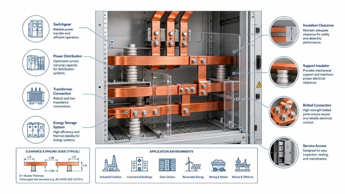
A copper rigid busbar is a fixed conductive component used to distribute electrical current between defined points. It can be straight or formed. It can be a simple flat strip or a complex 3D part with offsets, bends, holes, slots, tabs, coined areas, weld zones, selective plating, powder coating, heat-shrink insulation, or stamped features. In a low-current product, a busbar may be only a small connector. In a high-current system, it can become part of the core power architecture.
The word rigid does not mean the part must be thick and heavy. It means the conductor is intended to hold a controlled shape during installation and operation. This is different from a flexible laminated busbar, which uses stacked copper foils to absorb movement, or a braided copper busbar, which uses woven copper strands for multi-directional flexibility. JUMAI’s comparison article on Flexible Copper Busbar vs Solid Bars in Power Electronics is useful when a project is deciding between a fixed conductor and a movement-tolerant conductor.
A rigid busbar is normally selected when terminal positions are stable, assembly repeatability is important, and the conductor should support a defined path. Typical locations include battery main positive and negative paths, battery disconnect units, DC link connections, inverter terminals, capacitor bank connections, rack-level power distribution, UPS cabinets, switchgear links, data center power modules, and industrial control cabinets.
The engineering risk is that many buyers define the part too simply. A request such as “copper busbar, 500 A, tin plated” is not enough for a reliable quotation. The supplier still needs to know the operating temperature, duty cycle, allowable temperature rise, voltage, enclosure condition, terminal materials, plating area, insulation requirement, quantity, tolerance, inspection standard, and packaging needs.
A better way to understand a rigid busbar is to divide it into six design layers.
| Design layer | Main questions | Common buying mistake |
|---|---|---|
| Electrical layer | Continuous current, peak current, duty cycle, voltage drop, short-circuit requirement | Sizing the bar only by width and thickness |
| Thermal layer | Ambient temperature, airflow, enclosure condition, temperature-rise limit, nearby heat sources | Using free-air ampacity data for a sealed cabinet |
| Mechanical layer | Bend angle, hole tolerance, flatness, torque access, support points, vibration | Finding assembly problems only after prototypes arrive |
| Surface layer | Bare copper, tin plating, nickel plating, silver plating, selective plating, contact finish | Choosing plating only by unit price |
| Insulation layer | Creepage, clearance, coating thickness, dielectric strength, flame behavior, exposed windows | Treating insulation as cosmetic protection |
| Manufacturing layer | Cutting, punching, milling, bending, deburring, cleaning, plating, inspection, packaging | Approving a handmade sample without planning repeatable production |
Material selection: why “copper” is not a complete specification
Copper is popular for busbars because it has excellent electrical conductivity, thermal conductivity, corrosion resistance, formability, and plating compatibility. But “copper” is a broad word. A sourcing drawing should identify the material grade, temper, thickness, surface condition, and any required certificate or equivalent standard.
The current ASTM standard commonly discussed for copper sheet, strip, plate, and rolled bar is ASTM B152/B152M-24. Its scope covers a range of copper UNS numbers including C10100, C10200, C11000, C12000, C12200, and others. For busbar buyers, the practical lesson from this standard is simple: the purchase order should identify the copper grade. If the contract does not identify a specific copper, the supplier may have flexibility to furnish one of the listed coppers. That may be acceptable for some applications, but it is not ideal when electrical conductivity, oxygen content, formability, or joining behavior matters.
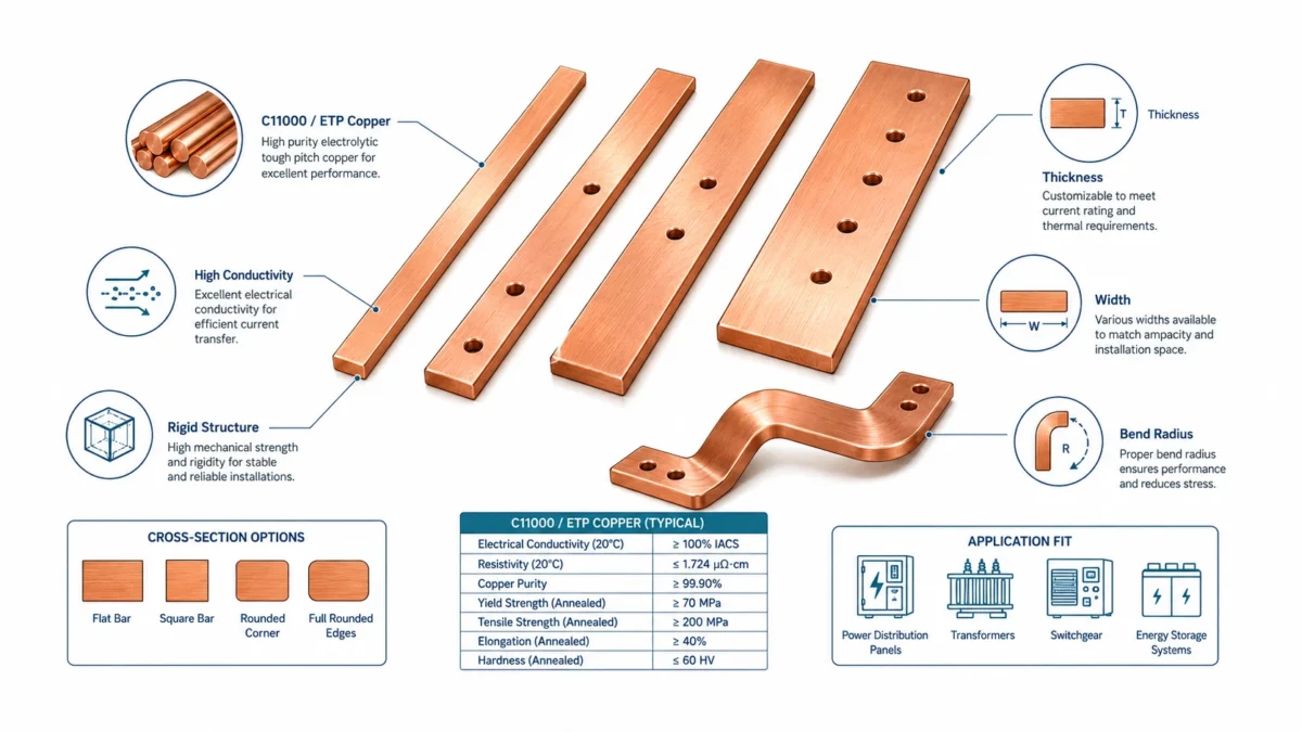
For high-current rigid busbars, the most common starting point is C11000 electrolytic tough pitch copper, often called ETP copper. The Copper Development Association alloy entry for C11000 identifies it as a high-conductivity copper with a minimum conductivity of 100% IACS in the annealed condition and a minimum copper content of 99.90%. C11000 is widely available, cost-effective compared with higher-purity specialty grades, and suitable for many stamped, punched, bent, and plated electrical conductors.
Oxygen-free copper, such as C10100 or C10200, may be specified when oxygen content, high-temperature joining, vacuum performance, or severe forming requirements justify the added cost. The Copper Development Association entry for C10100 notes that C10100 has a minimum conductivity of 101% IACS. In real busbar sourcing, this one-percent conductivity difference is not always the main reason to choose it. The more important reasons may be hydrogen embrittlement resistance, high-purity requirements, special brazing or welding needs, or customer-specific material standards.
Some projects also consider copper alloys with lower conductivity but higher mechanical strength. This can make sense for spring contacts, terminals, or parts that must carry load as a mechanical member. For typical rigid busbars carrying large current, however, high-conductivity copper grades remain the normal starting point.
| Material option | Typical reason to consider it | Practical caution for rigid busbars |
|---|---|---|
| C11000 ETP copper | High conductivity, strong availability, good formability, common for electrical conductors | Contains oxygen; welding or high-temperature reducing atmospheres require review |
| C10100 OFE copper | Very high purity, minimum 101% IACS conductivity, good for special electronic or vacuum-related applications | Higher cost and availability constraints may not be justified for ordinary power distribution |
| C10200 OF copper | Oxygen-free copper for applications needing lower oxygen content than ETP | Confirm equivalent standards and certificate requirements before quoting |
| C12200 DHP copper | Good forming and brazing behavior in many copper fabrication applications | Conductivity is lower than high-conductivity busbar copper, so it is usually not the first choice for high-current busbars |
| Copper alloys | Higher strength, spring behavior, or special mechanical properties | Lower conductivity can increase copper mass or temperature rise if used as the main conductor |
Conductivity, IACS, and what buyers should actually compare
IACS stands for International Annealed Copper Standard. It is a reference system used to compare conductor conductivity. When a buyer sees 100% IACS, it means the copper is being compared with the historical standard for annealed copper conductivity. Higher-conductivity copper may be listed slightly above 100% IACS because modern refining can exceed the original reference value.
For sourcing, IACS is useful, but it should not be used alone. The busbar’s electrical performance depends on both material conductivity and conductor geometry. A small difference between 100% and 101% IACS is less important than a poorly designed cross-section, a long current path, a hot enclosed environment, or a bad joint. A 1% material advantage can disappear quickly if the terminal pad is warped, the plating is porous, the bolt contact is uneven, or the design creates a current bottleneck around a hole.
A practical way to compare materials is to ask three questions. First, does the copper grade meet the required minimum conductivity? Second, can the selected temper be punched, bent, and handled without cracking, excessive springback, or deformation? Third, does the material match the intended plating, joining, insulation, and inspection route?
For many busbar projects, C11000 is the cost-performance baseline. Oxygen-free copper should be considered where the application has a clear technical reason. If the supplier recommends a substitute, the buyer should ask for the UNS number, conductivity, copper content, temper, standard, and certificate plan.
Temper and mechanical behavior: the hidden part of material selection
Material temper describes the condition of the copper after processing. Softer copper is easier to bend and form. Harder copper can offer better dimensional stability and handling resistance but may require larger bend radii or more careful forming control. This matters because a rigid busbar is often punched, bent, deburred, plated, insulated, and then shipped. Each step can change or reveal mechanical risk.
A straight busbar with only a few holes may tolerate a relatively broad material window. A 3D rigid busbar with multiple offsets, tight hole-to-bend distances, and selective plating needs more discipline. If the copper is too hard for the bend radius, cracking or surface tearing may occur. If it is too soft, the busbar may deform during packaging or installation. If the bend is too close to a punched hole, the hole may distort. If the edge is not deburred before insulation, the coating may be damaged.
At JUMAI, we normally discuss copper temper together with the manufacturing route. A prototype made by CNC cutting and hand-assisted bending can prove fit, but volume production may require stamping dies, dedicated bending fixtures, checking gauges, or different process sequencing. JUMAI’s experience with metal stamping dies for thin-gauge copper busbar parts helps us review these details before a program scales.
For the buyer, the safest approach is to avoid treating the sample as a one-off handmade part. The drawing, quotation, and approval process should connect the sample route to the production route. This is especially important when the annual volume is high, the copper part is thick, or the part has tight geometric tolerances.
Ampacity is not a single fixed number
One of the most common buyer questions is: how many amps can this rigid busbar carry? The answer is always conditional.
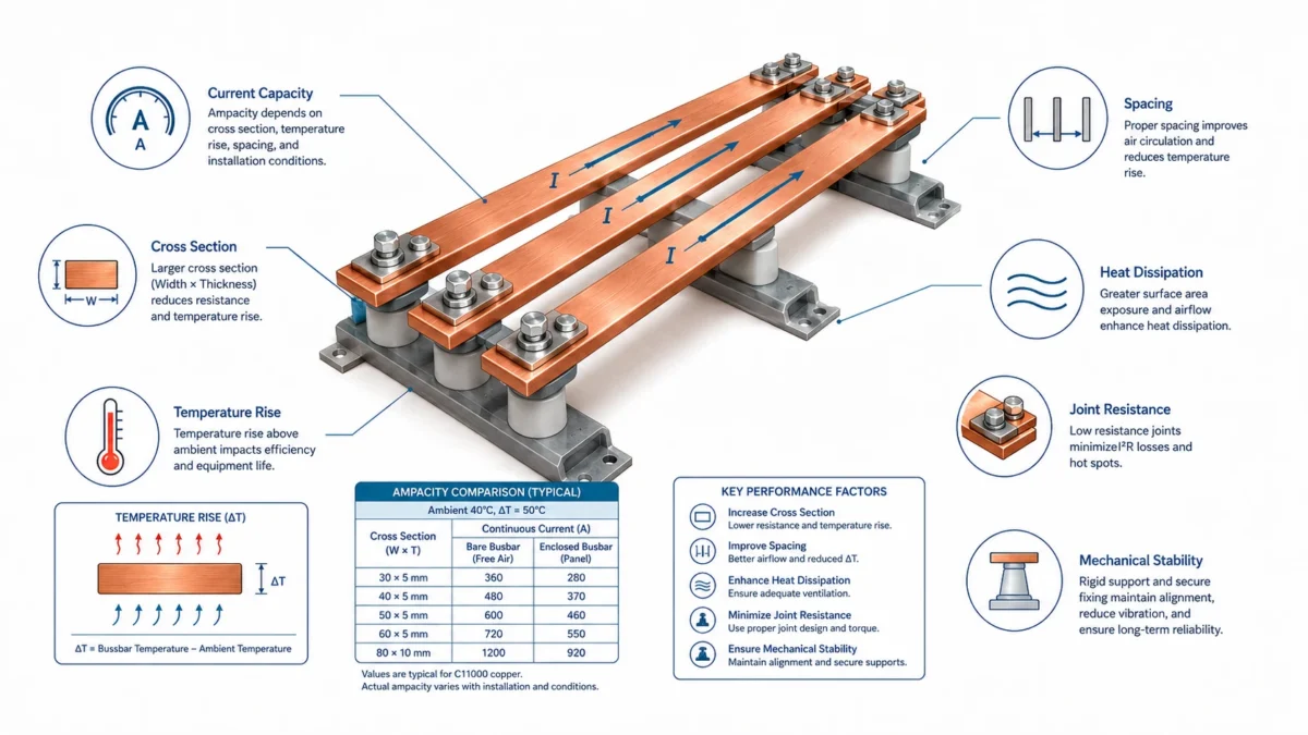
Ampacity depends on cross-sectional area, surface area, ambient temperature, allowable temperature rise, orientation, airflow, enclosure condition, surface emissivity, AC or DC current, frequency, spacing from other conductors, insulation, and joint resistance. The same copper bar may behave very differently in open air, inside a sealed battery pack, next to a heat source, or inside a ventilated switchgear cabinet.
The Copper Development Association’s busbar ampacity tables are a useful reference because they show rectangular copper busbar ampacities under specific temperature-rise assumptions. CDA explains that its tables are for rectangular Copper No. 110 busbars and are listed for 30°C, 50°C, and 65°C rises above ambient. It also recommends designing busbar systems for a 30°C rise above ambient or less for energy-efficiency considerations and states that temperature rises above 65°C are not recommended.
This is very important for commercial conversations. A busbar can often carry more current if a higher temperature rise is allowed, but that does not mean the design is better. Higher temperature can accelerate insulation aging, increase enclosure heat, create hot spots at joints, reduce safety margin, and affect nearby electronics. A lower-temperature design may require more copper or better cooling, but it may also improve reliability and reduce long-term system risk.
| Factor | Why it changes ampacity | Practical sourcing implication |
|---|---|---|
| Cross-sectional area | Larger area reduces resistance and heat generation | Width and thickness must be sized with real current and temperature assumptions |
| Surface area | More exposed surface improves heat dissipation | A wider flat bar may cool better than a compact thick bar of similar area |
| Ambient temperature | Higher ambient reduces thermal margin | EV packs, outdoor ESS cabinets, and data center cabinets need realistic temperature assumptions |
| Enclosure airflow | Forced airflow removes heat; sealed cabinets trap it | Free-air ampacity tables should not be copied blindly |
| Surface emissivity | Radiation cooling depends on surface condition | Surface treatments and coatings can affect heat dissipation |
| AC frequency and skin effect | AC current distribution may not be uniform in thick conductors | Large AC busbars need frequency and geometry review |
| Joint resistance | Poor contact creates local heating | Hole quality, flatness, plating, washer selection, and torque matter |
| Insulation | Insulation improves dielectric protection but can trap heat | Thermal and safety goals must be balanced together |
JUMAI’s Copper Busbar Ampacity Calculation Guide explains this issue in more detail. For RFQs, a useful statement is not simply “800 A busbar.” A better statement is: “800 A continuous, DC, 40°C ambient, inside a ventilated cabinet, with target busbar temperature rise below 30°C, tin-plated terminal pads, and insulation on non-contact areas.” That gives the supplier a real engineering target.
Sample ampacity data: why temperature rise changes the answer
The following table is adapted for practical discussion from the logic of public CDA busbar ampacity references. It is not a substitute for system validation, but it shows why buyers should avoid treating ampacity as a single number.
| Copper busbar example | Cross-section area | Design discussion | Buyer takeaway |
|---|---|---|---|
| Small flat bar | 1/8 in x 1 in = 0.125 in² | Suitable for moderate current in open-air or well-managed thermal environments | The same bar will run hotter in a sealed box than in free air |
| Wider flat bar | 1/8 in x 2 in = 0.250 in² | More area and more surface for cooling compared with the smaller bar | Width often improves cooling more efficiently than only increasing thickness |
| Thick compact bar | 1/4 in x 1 in = 0.250 in² | Similar area to 1/8 in x 2 in but less surface exposure | Similar copper mass does not always mean similar heat behavior |
| Large cabinet bar | 1/4 in x 4 in = 1.000 in² | Used in high-current cabinet, switchgear, UPS, and power distribution applications | Spacing, emissivity, airflow, and joints must be considered |
The CDA Table 4 on emissivity also shows that surface emissivity and the number of parallel busses can affect ampacity in a nonlinear way. For example, the table shows a 1/4 x 4 in. busbar at 30°C rise increasing from 1100 A at emissivity 0.15 to 1600 A at emissivity 0.9. That does not mean a buyer should simply apply a coating and assume a higher current rating. It means heat dissipation is part of design, and any surface treatment, coating, or enclosure condition should be validated under real operating conditions.
Voltage drop and power loss: the cost of small resistance
Resistance in a copper busbar is low, but it is never zero. At high current, small resistance becomes important because power loss follows the I²R relationship. If current doubles, resistive heating rises by four times for the same resistance. This is why a small increase in contact resistance at a joint can become a major hot spot.
Voltage drop matters in battery systems, inverters, UPS systems, data center power shelves, and DC distribution. In some systems, a few millivolts may seem small, but when multiplied by high current and many repeated connections, it becomes heat and efficiency loss. In a BESS rack with many repeated conductors, the effect can also influence module balancing and maintenance diagnostics.
The main conductor path is only one part of the resistance chain. The bolted joint may be more critical. Contact resistance depends on mating surface flatness, plating, cleanliness, oxide condition, contact pressure, washer design, bolt size, torque, terminal material, and long-term vibration or thermal cycling. A busbar with an excellent copper grade can still fail commercially if the joint design is poor.
This is one reason JUMAI emphasizes manufacturing details such as burr control, contact-pad flatness, plating consistency, cleaning, and packaging. A scratched or warped terminal pad is not a cosmetic issue. It can change contact pressure and heat behavior.
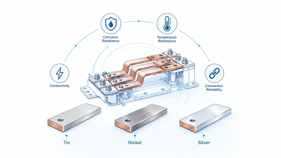
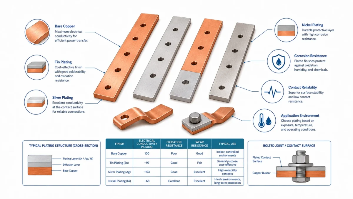
Plating options: why bare copper is not always enough
Copper conducts electricity well, but bare copper oxidizes and can be affected by storage, handling, humidity, and the operating environment. Plating is often used to protect contact surfaces, improve solderability, stabilize long-term contact behavior, or provide better wear and corrosion performance.
Tin plating is the most common practical choice for many industrial rigid busbars. The current active ASTM tin plating standard ASTM B545-22 covers electrodeposited tin coatings used to provide low contact resistance, corrosion protection, solderability, anti-galling behavior, and related functions. For many switchgear, ESS, cabinet, and general electrical applications, tin plating provides a good balance of cost and performance.
Nickel plating is considered when higher hardness, wear resistance, or elevated-temperature performance is needed. ASTM B733 covers autocatalytic electroless nickel-phosphorus coatings for engineering functions, including elevated-temperature service. In rigid busbars, nickel can be useful in harsh environments or wear-prone interfaces, but the full joint design must be evaluated because contact resistance and mating material compatibility still matter.
Silver plating is a premium option for demanding electrical contact applications. ASTM B700 covers electrodeposited silver coatings for engineering use and notes their use for solderable surfaces, electrical contact characteristics, high electrical and thermal conductivity, thermocompression bonding, wear resistance, and special reflectivity. Silver plating can improve contact performance, but it is more expensive and must be justified by the application.
Bare copper may still be acceptable for prototypes, protected internal areas, non-contact regions, or systems where oxidation is managed by design. But if the busbar will be stored, shipped internationally, installed in a humid environment, or used at a critical bolted interface, plating should be discussed early.
| Surface option | Typical advantage | Typical concern | Suitable use cases |
|---|---|---|---|
| Bare copper | Lowest surface-treatment cost and excellent base conductivity | Oxidation, fingerprints, storage marks, and variable contact surface | Early prototypes, protected internal areas, non-contact zones |
| Tin plating | Cost-effective oxidation protection, solderability, and practical contact behavior | Fretting, whisker concerns in some contexts, temperature limitations | ESS cabinets, switchgear, industrial power distribution, general rigid busbars |
| Nickel plating | Hardness, wear resistance, and better elevated-temperature capability | Contact resistance and mating surface must be reviewed | Harsh environments, high-temperature zones, wear-prone interfaces |
| Silver plating | Excellent electrical contact performance and high conductivity | High cost, tarnish management, and selective-use economics | Premium high-current contacts, specialized switchgear, critical connection pads |
| Insulated coating over copper | Dielectric protection, safer handling, and compact packaging | Can trap heat and requires controlled windows | EV packs, BESS racks, compact cabinets, data center power modules |
JUMAI’s article on Busbar Copper Plating Options for Corrosion Protection provides a plating-focused discussion for buyers comparing tin, nickel, silver, and other surface strategies.
Tin plating: the commercial baseline for many rigid busbars
Tin plating is popular because it solves several practical problems at a reasonable cost. It protects copper from rapid surface oxidation, provides a softer contact surface that can conform under pressure, and supports solderability when needed. It is also familiar to many electrical equipment buyers, which makes supplier comparison easier.
However, tin plating is not automatically correct for every project. Buyers should clarify whether the tin is matte or bright, whether underplating is required, whether contact areas are fully plated or selectively plated, what thickness is required, and how plating thickness will be measured. If the busbar has blind holes, deep bends, or masked insulation windows, the plating supplier must understand the geometry.
Tin-plated busbars also need packaging discipline. Heavy copper parts should not rub against each other during shipping. Contact surfaces should be separated or protected. Moisture control may be needed for long ocean shipments or humid storage. If parts arrive scratched, stained, or mixed by batch, the buyer may lose confidence even if the base copper is correct.
For many B2B programs, tin plating is the best starting point, but it should still be specified clearly. A drawing that says only “tin plated” invites different interpretations. A better drawing identifies the plated area, minimum thickness if required, appearance standard, masking zones, inspection method, and whether plating is required before or after bending.
Nickel plating: useful when environment and temperature are demanding
Nickel plating is harder than tin and can be more suitable for elevated-temperature, wear-prone, or harsher environments. It is often considered when the busbar is used in a high-temperature cabinet, a corrosive atmosphere, or an interface where repeated assembly and disassembly may occur. It may also be used as an underlayer for other finishes in specialized contact designs.
The caution is that nickel is not selected simply because it sounds stronger. The electrical contact behavior, surface hardness, mating material, bolt pressure, and operating environment must be reviewed together. A hard surface can be beneficial for wear resistance but may require more careful control of contact pressure to achieve stable low-resistance joints.
Nickel plating can also affect cost and lead time. Electroless nickel can provide relatively uniform coating on complex shapes, but the chemistry, phosphorus content, thickness, and post-treatment matter. The buyer should discuss whether the coating is intended mainly for corrosion resistance, wear resistance, temperature performance, or as an underlayer.
When a project involves outdoor ESS cabinets, marine-adjacent installations, high humidity, or elevated temperatures, nickel may deserve attention. But for many ordinary indoor cabinet connections, tin plating may be more commercially efficient.
Silver plating: high performance, but only where it pays back
Silver is highly conductive and has excellent contact characteristics. In critical high-current contact areas, silver plating can reduce contact resistance and improve performance. It is used in specialized electrical equipment, premium switchgear, contacts, and demanding power applications.
The problem is cost. Silver plating is much more expensive than tin and should usually be applied selectively rather than across the entire busbar unless the application requires it. Buyers should ask: is the entire busbar a contact surface, or only the pads around the bolt holes? Can selective plating achieve the same performance at lower cost? Is a nickel underlayer needed? How will silver tarnish be managed? What is the expected operating temperature and contact pressure?
Silver plating can be the correct choice when the failure cost is high and the contact performance benefit is real. But it is not a universal upgrade. In a well-designed industrial cabinet with stable bolted joints and moderate environment, tin plating may offer a better cost-performance balance.
Selective plating and exposed windows: reducing cost without reducing function
Many rigid busbars do not need the same surface treatment everywhere. The terminal pads need controlled contact behavior. Non-contact areas may need insulation or may simply need basic corrosion control. A selective plating strategy can reduce cost, especially when silver or nickel is used only on critical pads.
Selective plating must be designed into the drawing. The supplier needs to know the mask boundaries, tolerance of the plating edge, exposed terminal window size, and whether the plating edge will be covered by insulation. A poor mask design can create plating shadows, unprotected copper at the wrong location, or coating buildup near holes.
The same is true for insulation windows. If a powder-coated or heat-shrink insulated busbar has exposed pads, the window size must match the washer, bolt, mating terminal, and torque tool. If the window is too large, creepage and clearance may be reduced. If it is too small, the washer may sit partly on insulation, reducing contact pressure and creating heat.
A good busbar drawing should therefore define both plating and insulation as functional features, not afterthoughts.
Insulation, creepage, and clearance
Rigid busbars often operate in systems where shock protection, dielectric strength, creepage, clearance, and flame behavior matter. Insulation can include heat-shrink tubing, PVC sleeves, PET film, PA coating, epoxy powder coating, PI film, molded covers, or assembled barriers. The correct option depends on voltage, temperature, mechanical exposure, bend geometry, coating windows, and assembly method.
For low-voltage equipment, standards such as IEC 60664-1:2020+AMD1:2025 deal with insulation coordination, including clearances, creepage distances, and solid insulation for equipment within low-voltage supply systems. For low-voltage switchgear and controlgear assemblies, IEC 61439-1:2020 lays down general definitions, service conditions, construction requirements, technical characteristics, and verification requirements. These standards may or may not directly govern a specific customer product, but they show the type of thinking serious buyers apply to electrical safety.
Insulation design should never be separated from thermal design. A fully insulated busbar may be safer to handle and easier to package inside a compact module, but insulation can reduce heat dissipation. If a design depends on the copper surface to release heat, the insulation material, thickness, and coverage must be reviewed. In some cases, a molded cover or mechanical barrier may be better than coating the entire conductor.
Flame behavior can also matter. Materials used near high-current electrical parts may be requested with flammability ratings such as UL 94. The UL 94 standard covers tests for flammability of polymeric materials used for parts in devices and appliances. Buyers should not assume that a sleeve, coating, film, or molded cover is automatically acceptable for every market. The material grade, thickness, rating, and documentation should match the end product’s compliance path.
Geometry and current flow: holes, bends, and bottlenecks
A rigid busbar is not only a rectangle. Once holes, slots, notches, bends, and windows are added, current flow changes. A hole reduces local cross-section. A narrow neck can become a current bottleneck. A sharp inside corner can concentrate current density and mechanical stress. A bend can change heat orientation and assembly clearance. A slot may help tolerance but reduce conductive area.
This does not mean holes and bends should be avoided. They are necessary. The goal is to design them intelligently. Hole diameter should match the fastener and washer system. Edge distance should prevent deformation. Bend radius should match copper thickness and temper. Hole-to-bend distance should allow forming without distortion. Slots should be used only where tolerance compensation is needed.
For compact electrical cabinets, geometry can be as important as material. JUMAI’s guide on Rigid Busbar Design for Compact Cabinets discusses how controlled conductor routing helps when cabinet space is limited. A small change in offset, bend direction, or terminal pad shape can improve assembly access and reduce risk.
Buyers should also consider serviceability. Can a technician reach the bolt with a torque wrench? Can the part be removed without disassembling half the cabinet? Are polarity marks visible after installation? Is the busbar protected from accidental contact? These questions are not minor. They determine whether a technically correct part is practical in the field.
Joints, contact resistance, and torque control
Many busbar failures occur not in the middle of the copper bar, but at the joint. The conductor may be correctly sized, but the terminal interface overheats because the contact area is too small, the pad is not flat, the plating is wrong, the bolt torque is inconsistent, or burrs prevent full contact.
A bolted joint works by creating contact pressure between surfaces. The real metal-to-metal contact happens at microscopic high points. Plating, surface roughness, flatness, washer selection, and torque all influence the effective contact area. If contact pressure is too low, resistance rises. If torque is too high, threads, washers, or copper may deform. If a washer sits on insulation or over a burr, the joint may look tight but perform poorly.
For critical programs, the buyer should define torque values, washer type, bolt grade, mating material, and inspection expectations. Thermal imaging during validation can reveal hot spots. A torque audit during assembly can reveal process variation. If vibration is expected, locking strategy and joint retention should be reviewed.
In EV and industrial systems, thermal cycling can also change joint pressure over time. Copper, steel bolts, aluminum terminals, and insulation materials expand differently. This is another reason plating and joint stack design should be reviewed as a system.
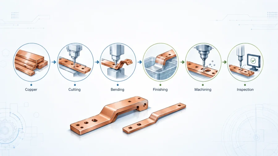
Manufacturing workflow: from copper stock to finished busbar
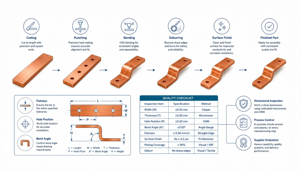
A reliable custom rigid busbar comes from a controlled manufacturing route. The exact route depends on material, thickness, geometry, quantity, plating, and insulation, but a typical workflow includes material preparation, blanking, punching or milling, deburring, bending, cleaning, plating, insulation, marking, inspection, and packaging.
For prototypes, CNC cutting, milling, and manual-assisted bending may be efficient because they avoid tooling cost. For volume production, stamping dies, bending fixtures, and gauges may reduce cost and improve repeatability. The supplier should explain how the sample route can transition into the production route.
JUMAI’s Advanced Manufacturing Techniques for High-Ampacity Precision Copper Busbars describes how material science, forming, stamping, plating, and inspection connect in high-current copper components. This integrated view is important because a busbar rarely exists alone. It may interact with brackets, terminals, covers, housings, stamped accessories, and deep-drawn protection parts.
| Process step | Main purpose | Quality focus |
|---|---|---|
| Material selection | Match copper grade, temper, thickness, and certificate requirement | Grade traceability and surface condition |
| Cutting or blanking | Create the flat profile | Length, width, squareness, edge condition |
| Punching or milling | Create holes, slots, terminal features, and windows | Hole diameter, positional tolerance, burr height |
| Bending or forming | Create offsets and 3D routing | Bend angle, radius, flatness, springback control |
| Deburring and edge rounding | Remove sharp edges and unsafe burrs | Operator safety, plating quality, insulation protection |
| Cleaning | Prepare surface for plating or insulation | Oil, oxide, fingerprints, and contamination control |
| Plating | Protect contact areas and improve contact behavior | Thickness, adhesion, appearance, masked zones |
| Insulation | Provide dielectric protection and handling safety | Coverage, thickness, adhesion, exposed windows |
| Inspection | Confirm conformance before shipment | Critical dimensions, surface, plating, insulation, labels |
| Packaging | Prevent damage in transit and storage | Separation, moisture control, deformation prevention |
Burrs and edges: small defects with large consequences
Burrs are easy to underestimate. A burr around a punched hole can prevent a terminal from sitting flat. A sharp edge can cut insulation. A raised burr can affect plating thickness. A rough edge can become a safety hazard for workers and technicians. In high-voltage systems, sharp points can also become locations of electric field concentration.
For rigid busbars, deburring is not cosmetic. It is part of electrical and insulation reliability. The required edge condition depends on application. A prototype may only need safe handling, while an insulated EV busbar may require a controlled radius to protect coating. If the part will be powder coated or sleeved, the edge quality should be reviewed before insulation.
Buyers should ask suppliers how burrs are controlled and inspected. Visual inspection alone may not be enough for tight terminal pads or critical insulation areas. Process controls may include tooling maintenance, punch-die clearance control, tumbling, brushing, manual deburring, edge rounding, and first-article inspection.
Thermal validation: free-air data is only a starting point
Public ampacity tables are useful, but the final system determines real performance. A busbar inside a data center cabinet may be near other heat sources. A busbar inside an EV battery pack may have limited airflow. A busbar inside an outdoor ESS container may see high ambient temperature and solar loading. A busbar inside switchgear may be affected by enclosure design, conductor spacing, and load diversity.
Thermal validation can include calculation, simulation, prototype testing, and infrared inspection. For low-risk applications, conservative sizing and known design history may be enough. For high-current or safety-critical applications, temperature-rise testing under realistic load is recommended. The busbar should be tested with the real joint stack, torque, enclosure, airflow, insulation, and neighboring components whenever possible.
The goal is not only to see whether the copper survives. The goal is to confirm that the busbar, terminals, insulation, connected devices, and surrounding structure remain within their intended temperature limits. A busbar that runs hot may still pass a short functional test, but it can reduce long-term reliability.
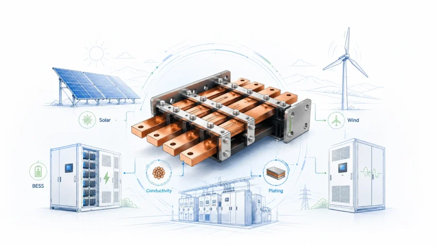
Application differences: EV, ESS, data center, and switchgear
Rigid busbars are used across many industries, but each application has different priorities.
In electric vehicles, packaging, vibration, thermal cycling, insulation, service safety, and weight are important. Rigid busbars are valuable for fixed high-current routes such as battery main conductors, high-voltage junction boxes, inverter DC links, and charging paths. But where movement, tolerance stack-up, or vibration is significant, flexible or braided copper may be better.
In battery energy storage systems, repeatability and documentation are major concerns. A BESS container or rack can include large numbers of repeated electrical interfaces. Small improvements in busbar geometry, hole quality, plating, marking, or packaging can create large savings when repeated across many cabinets. Surface treatment may also be more important in outdoor or humid environments.
In data centers and AI infrastructure, compact power density and uptime matter. Rigid busbars may be used in UPS cabinets, rack PDUs, switchgear, rectifier assemblies, power shelves, and busway interfaces. A low-cost part that creates downtime risk is not truly low cost. Inspection, plating consistency, and thermal validation should be part of the sourcing conversation.
In industrial switchgear and power distribution, standards, short-circuit withstand, temperature rise, and service access are often central. Busbars may be larger, but that does not make them simple. Spacing, support, mechanical strength, and thermal performance must be validated inside the actual assembly.
| Application | Rigid busbar value | Key design caution |
|---|---|---|
| EV battery pack | Compact fixed path, repeatable installation, lower voltage drop | Vibration, thermal expansion, insulation windows, service safety |
| Battery energy storage | Repeatable rack and cabinet connections | Corrosion, documentation, torque access, batch consistency |
| Data center power systems | Low-loss compact distribution for high-density equipment | Hot cabinets, uptime risk, inspection discipline |
| Industrial switchgear | Strong high-current paths and defined spacing | Temperature rise, short-circuit withstand, assembly verification |
| Renewable energy inverter | Short DC links and controlled geometry | Thermal cycling, EMI layout, capacitor and module interface |
| Charging infrastructure | High-current input and output paths | Contact heating, plating, service access, environmental exposure |
RFQ checklist: how to get a more accurate quote
The quality of a rigid busbar quote depends heavily on the quality of the RFQ. If a buyer provides only a rough size and current rating, every supplier must guess. Those guesses may make quotes look cheaper or more expensive than they really are.
A strong RFQ should include the 2D drawing, 3D model if available, copper grade, temper if known, thickness, required conductivity, current profile, voltage, duty cycle, temperature-rise target, operating environment, plating requirement, insulation requirement, prototype quantity, annual forecast, inspection documents, packaging needs, and target approval timeline.
If some variables are open, say so clearly. A good supplier can help optimize copper mass, bend radius, hole shape, plating area, and insulation window. But the supplier should not silently make assumptions about performance-critical requirements.
| RFQ item | Minimum information to provide | Why it matters |
|---|---|---|
| Application | EV, ESS, data center, switchgear, inverter, UPS, charger, or other system | Helps evaluate environment and risk level |
| Electrical rating | Continuous current, peak current, duty cycle, voltage, short-circuit condition | Drives cross-section and validation needs |
| Thermal target | Ambient temperature, airflow, enclosure condition, allowable temperature rise | Prevents under-designed parts in hot cabinets |
| Mechanical data | 2D drawing, 3D file, hole positions, bend angles, tolerances | Controls fit and repeatability |
| Material | Copper grade, temper, thickness, equivalent standards | Avoids vague “copper” substitutions |
| Plating | Tin, nickel, silver, bare copper, selective plating, thickness, masked zones | Affects cost, lead time, contact behavior, and corrosion protection |
| Insulation | Material, thickness, color, exposed windows, dielectric requirement | Affects safety, clearance, thermal behavior, and assembly |
| Quantity | Prototype, pilot batch, annual forecast, release schedule | Determines whether CNC, fixtures, or stamping dies are appropriate |
| Quality documents | Material certificate, dimensional report, plating report, FAI, PPAP-style documents | Supports approval and traceability |
| Packaging | Part separation, moisture control, labeling, export packaging | Prevents deformation, scratching, oxidation, and mixed batches |
Cost drivers procurement teams should understand
Copper mass is often the most visible cost driver, but it is not the only one. A rigid busbar price can be affected by material grade, thickness, geometry, bend complexity, hole tolerance, plating, insulation, masking, inspection, documentation, packaging, volume, tooling, and copper market movement.
The cheapest unit price is not always the lowest project cost. If a low-cost busbar arrives with burrs, warped bends, poor plating, inconsistent insulation, missing labels, or no inspection data, the buyer may pay through rework, delayed validation, line stoppage, field service, or customer complaints.
The best cost reduction usually comes from value engineering. Can the current path be shortened? Can width solve heat more efficiently than thickness? Can the hole pattern be standardized? Can a bend be moved away from a hole? Can selective plating replace full plating? Can tolerance be tightened only where functional? Can packaging be improved to prevent damage instead of adding more inspection later?
| Cost driver | How it affects price | Practical optimization |
|---|---|---|
| Copper mass | Direct material cost and shipping weight | Optimize cross-section using real current and temperature assumptions |
| Thickness | Affects material cost, bending force, and bend radius | Avoid unnecessary thickness when width can improve cooling |
| Geometry complexity | Increases setup, fixtures, and inspection | Simplify bends and avoid tight hole-to-bend distances |
| Hole pattern | Dense or tight-tolerance holes increase process control | Standardize hole sizes and tolerances where possible |
| Plating | Adds process cost and lead time | Use selective plating where only pads need premium finish |
| Insulation | Adds material, labor, masking, and inspection | Define exposed windows clearly and avoid over-complex shapes |
| Documentation | Requires inspection time and record control | Define reports early instead of adding requirements late |
| Volume | Changes the best manufacturing route | Separate prototype, pilot, and mass-production pricing |
How JUMAI supports custom copper rigid busbar projects
JUMAI supports global customers with custom rigid copper busbars, flexible copper busbars, braided copper busbars, precision stamped components, deep-drawn components, precision stamping dies, and related accessories. This matters because a busbar often works together with other formed metal parts. A battery system may need rigid busbars, flexible connectors, brackets, terminal plates, protective covers, and stamped parts. A data center cabinet may need busbars, shields, mounting hardware, and precision metal supports.
Our Precision Copper Busbars capability is built around engineering review, custom manufacturing, and practical production support. For early-stage projects, we can help review drawings and identify risks such as insufficient bend radius, hole distortion, unclear plating zones, exposed-window conflicts, difficult torque access, unnecessary copper mass, or tight tolerances that raise cost without adding performance. For mature projects, we can support sampling, dimensional reports, plating coordination, insulation review, packaging, and repeat production.
JUMAI’s broader metal forming background is also useful for customers who need more than one conductor. The same manufacturing mindset behind precision stamping dies and deep-drawn components can help improve busbar repeatability. Instead of treating the busbar as an isolated copper strip, we can review how it interfaces with the enclosure, bracket, terminal, fuse, contactor, sensor, or cover.
For procurement teams, our goal is commercial clarity. We help customers separate prototype assumptions from production assumptions, discuss copper mass and plating cost honestly, and align inspection and packaging expectations before volume release. A strong busbar project should not surprise the buyer after the first batch. It should be engineered, quoted, sampled, validated, and scaled with a clear path.
Practical selection guide: material, plating, and performance together
The best rigid busbar choice is not the thickest copper, the most expensive plating, or the tightest tolerance. It is the part that meets the electrical, thermal, mechanical, safety, manufacturing, and commercial requirements at the same time.
For most high-current industrial busbars, start with C11000 ETP copper unless the application has a clear reason to use oxygen-free copper or another grade. Define the current profile and temperature-rise target before choosing the final cross-section. Use public ampacity tables only as references, not as final proof for a closed cabinet or high-risk system. Select plating based on contact behavior and environment, not only appearance. Define insulation windows around the real joint stack. Control burrs, flatness, and packaging because these details affect performance.
The decision flow below is a practical starting point.
| Decision point | Recommended question | Practical direction |
|---|---|---|
| Material grade | Is ordinary high-conductivity ETP copper sufficient? | Use C11000 for many standard high-current rigid busbars |
| Purity requirement | Is oxygen-free copper required by welding, vacuum, forming, or customer specification? | Consider C10100 or C10200 only when justified |
| Cross-section | What current, duty cycle, ambient, and temperature rise must be met? | Size by real thermal conditions, not only a rule of thumb |
| Plating | What environment and mating surface will the busbar see? | Tin for many general cases; nickel or silver for specific higher-demand interfaces |
| Insulation | What voltage, creepage, clearance, and handling protection are required? | Define coating material, thickness, exposed windows, and dielectric expectations |
| Geometry | Are holes, bends, and slots manufacturable and electrically safe? | Review bend radius, neck-down areas, current bottlenecks, and torque access |
| Validation | What must be proven before production? | Check fit, torque access, contact surface, temperature rise, insulation, and packaging |
| Commercial scale | Is the prototype route suitable for mass production? | Align CNC, tooling, fixtures, inspection, and batch packaging early |
Conclusion: a rigid busbar is a business decision as much as an engineering part
Copper rigid busbars are essential because they bring order to high-current power distribution. They control the electrical path, reduce assembly variation, improve serviceability, and support compact design. But their reliability depends on decisions that must be made before the purchase order: copper grade, temper, cross-section, plating, insulation, hole quality, bend control, contact interface, thermal validation, inspection, and packaging.
A buyer who treats a rigid busbar as a simple copper strip may save time during RFQ, but may create risk later. A buyer who defines performance requirements clearly can compare suppliers more intelligently and avoid hidden costs. The right supplier should not only quote the drawing. The supplier should ask practical questions, identify manufacturability risks, explain plating and insulation trade-offs, and help the project move from prototype to repeatable production.
At JUMAI, we approach Rigid Busbars as engineered power components. Whether the project is for EV battery systems, battery energy storage, data center power distribution, industrial switchgear, renewable energy inverters, or custom high-current equipment, we help customers connect material selection, plating options, and performance validation into one practical manufacturing plan. If your team is developing a new rigid copper busbar or optimizing an existing design, the strongest next step is to share your drawing, current profile, operating environment, plating expectations, and target quantity so the design can be reviewed before cost and risk become locked in.