Renewable energy projects are no longer small experimental installations. Solar farms, wind power systems, hybrid plants, grid-connected battery energy storage systems, power conversion skids, EV charging hubs, and renewable-powered data infrastructure are becoming larger, denser, and more commercially demanding. For EPCs and OEMs, this shift changes the role of electrical interconnection hardware. A copper conductor is not only a current path. In a renewable energy system, it is also part of the thermal design, short-circuit design, enclosure layout, assembly workflow, maintenance strategy, and long-term reliability plan.
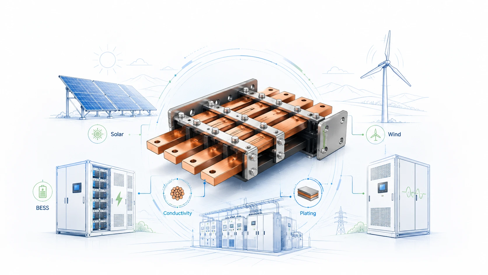
This is where Rigid Busbars become especially important. A rigid busbar is a formed copper or aluminum conductor used to distribute high current between fixed electrical points. In renewable energy equipment, copper rigid busbars are commonly used in combiner cabinets, inverter DC links, power conversion systems, battery racks, switchgear, transformer interfaces, control cabinets, UPS systems, and power distribution modules. Compared with loose cable routing, a custom rigid busbar gives the engineering team more control over geometry, contact surface, thermal behavior, creepage and clearance, assembly repeatability, and inspection standards.
For JUMAI, this topic is directly connected to our work in custom copper busbars, precision metal forming, deep-drawn components, and custom metal accessories. A renewable energy project rarely needs only one type of conductor. A solar inverter may need rigid busbars for fixed DC paths, flexible copper busbars for tolerance compensation, braided copper conductors for vibration isolation, stamped brackets for support, and formed covers for protection. As discussed in JUMAI’s article on custom rigid busbars for EV, energy storage, and data center applications, the best conductor choice depends on the electrical path, mechanical environment, assembly sequence, and production target.
The purpose of this article is to give EPCs, OEM engineers, purchasing managers, and project developers a practical buying and design guide. It explains where rigid busbars fit in renewable energy systems, what technical information should be prepared before sourcing, how to compare copper grades and surface treatments, why ampacity cannot be treated as a single fixed number, and how JUMAI can support custom rigid busbar projects from prototype to production.
Table of Contents
Why renewable energy growth makes busbar design more important
Renewable energy growth is now a major global infrastructure trend. According to the International Renewable Energy Agency’s Renewable Capacity Highlights 2026, global renewable power capacity reached 5,149 GW at the end of 2025, after a record annual increase of 692 GW, or 15.5% year-on-year growth. IRENA also reported that solar capacity increased by 511 GW and wind capacity by 159 GW in 2025, with solar and wind together accounting for 96.8% of net renewable additions.
The International Energy Agency also expects strong growth to continue. In its Renewables 2025 analysis, the IEA projected that renewable power capacity could increase by almost 4,600 GW between 2025 and 2030, with solar PV representing nearly 80% of the global increase. The same analysis noted that renewables are expected to meet more than 90% of global electricity demand growth over 2025-2030.
These numbers matter for rigid busbars because each new megawatt of renewable generation requires more than panels or turbines. It requires power conversion, protection, switching, storage, monitoring, and grid connection equipment. Inside that equipment, current must move safely and efficiently through conductors that can survive heat, vibration, installation variation, environmental exposure, and fault conditions.
Battery energy storage adds another layer. The IEA Global Energy Review 2026 stated that battery storage was the fastest-growing power technology in 2025, with 108 GW of new capacity deployed worldwide, 40% more than in 2024. About 80% of that new battery capacity was utility-scale. For EPCs and OEMs, this means more repeated electrical joints in battery modules, racks, PCS cabinets, DC combiner sections, containerized systems, and substation interfaces. A small resistance problem in one connection can become a large production or field risk when repeated thousands of times.
| Market signal | Public data point | Busbar implication for EPCs and OEMs |
|---|---|---|
| Global renewable capacity | IRENA reported 5,149 GW of renewable capacity by the end of 2025 | More switchgear, inverters, combiner boxes, battery systems, and grid interfaces require engineered conductors |
| Annual renewable additions | IRENA reported 692 GW added in 2025 | Project schedules become tighter, and standardized busbar designs can help reduce assembly variation |
| Solar growth | IRENA reported 511 GW of solar capacity added in 2025 | Solar inverters, DC cabinets, string combiners, and energy storage couplings need compact high-current paths |
| Wind growth | IRENA reported 159 GW of wind additions in 2025 | Nacelles, converters, transformers, and tower-base cabinets need conductor systems designed for vibration and corrosion risk |
| Battery storage | IEA reported 108 GW of battery storage additions in 2025 | Battery racks and PCS sections require low-resistance, repeatable, serviceable interconnections |
| Storage target | IEA states global storage capacity must increase sixfold to 1,500 GW by 2030 in its NZE pathway | OEMs need scalable conductor designs that can be validated, documented, and reproduced across projects |
The commercial point is simple: as renewable energy systems scale, the cost of electrical interconnection mistakes rises. A poorly designed busbar may not be the most expensive line item in the bill of materials, but it can create expensive consequences: hot spots, voltage drop, failed insulation, field rework, loose joints, delayed commissioning, and warranty claims.
What Rigid Busbars do inside renewable energy systems
Rigid busbars are most valuable where the electrical route is stable and fixed. They are not used because they can bend easily during service; they are used because they hold a precise shape after manufacturing. That stable shape is useful in renewable energy equipment because it improves routing discipline and reduces the need for operator-dependent cable placement.
In a utility-scale solar system, rigid busbars may appear in DC combiner boxes, inverter input sections, AC output cabinets, auxiliary power panels, and transformer-side switchgear. In a hybrid solar-plus-storage plant, they may also appear in battery rack outputs, DC bus sections, power conversion systems, and containerized switchboards. In wind energy systems, rigid busbars are common in lower-vibration fixed cabinets and electrical distribution sections, while flexible or braided conductors may be selected near dynamic interfaces. In microgrids and renewable-powered industrial facilities, rigid busbars can help organize power distribution inside compact enclosures where multiple sources and loads must be connected.
A rigid busbar performs several functions at the same time. Electrically, it carries current with lower resistance than an undersized or poorly terminated conductor. Thermally, it dissipates heat through its surface area and helps define the temperature rise of the assembly. Mechanically, it can support a fixed routing path and sometimes acts as a structural connection between components. From a manufacturing viewpoint, it creates repeatability because its hole pattern, bend angle, terminal face, and insulation window are already controlled before assembly.
This is why EPCs and OEMs should not treat a rigid busbar as a commodity copper strip. The finished part may look simple, but its performance depends on copper grade, temper, cross-section, bend radius, hole tolerance, burr control, plating thickness, insulation system, joint design, torque access, and packaging protection. These details decide whether the busbar fits smoothly during assembly and whether it remains reliable after years of thermal cycling.
A practical way to understand rigid busbar value is to compare it with cable routing. Cable has flexibility, which is useful when the route is uncertain or movement must be absorbed. However, cable routing also depends heavily on installer skill. Bend radius, lug orientation, crimp quality, tie-down positions, and contact pressure can vary between technicians. A custom rigid busbar reduces that variation. It fits one defined path and forces the electrical connection into a controlled geometry.
For compact equipment, this controlled geometry becomes even more important. JUMAI’s guide on rigid busbar design for compact cabinets explains why high-density power enclosures require attention to heat dissipation, insulation windows, structural integrity, and bend accuracy. Renewable energy OEMs face similar pressure because inverters, BESS cabinets, and DC distribution systems are increasingly expected to handle higher power in smaller footprints.
EPC and OEM requirements are not the same
EPCs and OEMs often discuss the same renewable energy project, but they evaluate rigid busbars from different perspectives. Understanding this difference helps suppliers provide better recommendations.
An EPC usually looks at the complete project: schedule, procurement, installation, commissioning, documentation, maintainability, and project risk. The EPC wants components that can arrive on time, fit correctly, pass inspection, and support fast field installation. If a busbar design requires difficult torque access or creates unclear field wiring steps, the EPC may face delayed commissioning. If the supplied busbar documentation is weak, the EPC may struggle with owner review, utility acceptance, or warranty documentation.
An OEM usually looks deeper into product design. The OEM is concerned with repeatable manufacturing, cost control, design validation, testing, compliance, and serviceability over multiple production batches. The OEM wants a busbar that can be produced consistently, installed quickly, and validated as part of a larger assembly. The OEM may also care about DFM suggestions, tooling investment, sample approval, production control plans, and long-term supply continuity.
These priorities overlap, but they are not identical. An EPC may ask for faster delivery and project documents. An OEM may ask for tighter tolerances, stable plating, PPAP-style documentation, and prototype-to-volume consistency. A strong custom busbar supplier should be able to support both modes. At JUMAI, this is one reason we position rigid busbars as part of a broader precision copper busbar portfolio, not as isolated pieces of copper.
| Buyer type | Main concern | What they should specify in the RFQ | What to avoid |
|---|---|---|---|
| EPC contractor | Fast installation, project schedule, documentation, commissioning risk | Cabinet layout, current rating, voltage level, environmental conditions, inspection requirements, packaging and labeling | Asking only for price per kilogram or price per piece without installation context |
| Renewable equipment OEM | Repeatable product performance, validation, DFM, production cost | Drawings, 3D files, tolerance stack-up, duty cycle, temperature rise target, plating, insulation, batch traceability | Treating the prototype as a handmade one-off part without a production plan |
| Inverter or PCS manufacturer | Low inductance, thermal control, power module interface, DC link layout | Positive/negative routing, capacitor interface, hole flatness, contact resistance, creepage/clearance requirements | Ignoring electromagnetic layout and busbar spacing until late validation |
| BESS integrator | Rack repeatability, service access, fault protection, insulation safety | Battery chemistry, rack current, short-circuit assumptions, maintenance clearances, insulation class | Copying a cable design into a busbar design without checking tolerance and thermal expansion |
| Switchgear or cabinet builder | Standards alignment, short-circuit withstand, heat rise, mounting support | Assembly standard, busbar supports, bracing plan, rated current, rated short-time withstand current | Assuming busbar cross-section alone proves the assembly rating |
When an RFQ clearly identifies the buyer’s role and design intent, the supplier can quote more accurately. It also reduces the back-and-forth that slows down renewable energy projects.
Electrical sizing: ampacity is not a single number
One of the most common mistakes in rigid busbar sourcing is asking, “How many amps can this copper bar carry?” The question is understandable, but it is incomplete. Ampacity depends on cross-section, conductor material, ambient temperature, enclosure ventilation, permissible temperature rise, installation orientation, surface condition, nearby conductors, insulation, duty cycle, and standards used by the final assembly.
For a simple first discussion, engineers may start with cross-section and DC resistance. Copper’s conductivity is a major reason it is widely used in high-current systems. The Copper Information Center explains that the International Annealed Copper Standard defines 100% IACS copper at 20°C with volume resistivity of 0.017241 ohm-mm²/m, and that high-conductivity copper can reach or exceed 101% IACS in routine production. The Copper Development Association also lists massive fully dense copper with electrical resistivity of 1.71 microhm-cm and electrical conductivity of 101% IACS at 68°F.
These values are useful for understanding voltage drop and I²R loss. However, they do not replace thermal validation. A copper busbar in open air, a busbar inside a hot sealed inverter, and an insulated busbar close to another conductor may have very different temperature behavior even if the cross-section is the same.
The simplified table below uses the 100% IACS resistivity value of 0.017241 ohm-mm²/m to compare DC resistance only. It assumes a 1-meter conductor length and 600 A current. It does not include joint resistance, AC effects, enclosure temperature, insulation, or heat dissipation limits.
| Copper busbar size | Cross-section area | Approx. resistance over 1 m | Voltage drop at 600 A | I²R loss over 1 m |
|---|---|---|---|---|
| 20 x 3 mm | 60 mm² | 0.287 mΩ | 0.172 V | 103.4 W |
| 30 x 5 mm | 150 mm² | 0.115 mΩ | 0.069 V | 41.4 W |
| 50 x 5 mm | 250 mm² | 0.069 mΩ | 0.041 V | 24.8 W |
| 60 x 10 mm | 600 mm² | 0.029 mΩ | 0.017 V | 10.3 W |
The table shows why cross-section matters. A larger conductor reduces resistance and heat generation. But in real equipment, the largest conductor is not always the best answer. Oversizing copper can increase cost, weight, bending difficulty, terminal stress, and space consumption. In some cases, using two thinner busbars in a controlled parallel arrangement may improve surface area and layout. In other cases, a wider but thinner busbar may dissipate heat better than a narrow thick bar, depending on airflow and proximity.
JUMAI’s copper busbar ampacity calculation guide discusses why temperature rise, surface area, and installation environment must be considered together. For EPCs and OEMs, the best practice is to provide the supplier with current, duty cycle, voltage, ambient temperature, enclosure condition, expected temperature rise limit, and any applicable standard or internal specification. With that information, the busbar can be sized as part of the system rather than guessed from a generic ampacity chart.
Thermal management and temperature rise
In renewable energy systems, heat is both an efficiency issue and a reliability issue. Any resistance in the conductor or joint creates heat. That heat can accelerate insulation aging, reduce equipment life, increase cabinet temperature, and create uncomfortable or unsafe service conditions.
Rigid busbars help thermal management in several ways. First, copper’s high thermal conductivity spreads heat away from hot spots. Second, the flat surface of a busbar provides more predictable heat dissipation than a bundle of cables with uneven spacing. Third, a rigid busbar can be designed with wider areas near high-current sections, narrower neck-downs where space is limited, or additional mounting support where heat and mechanical stress overlap.
However, rigid busbars can also create problems if thermal expansion is ignored. Copper expands when heated. In a long conductor path, repeated temperature cycling can stress terminals, insulators, and bolted joints. A perfectly straight rigid busbar between two fixed terminals may look clean in CAD, but if the temperature swing is high and the endpoints cannot move, the busbar can transfer expansion stress into connected components. In some designs, formed offsets, expansion loops, slotted mounting holes, flexible links, or hybrid rigid-flexible conductor strategies are needed.
Thermal design should also consider contact resistance. A thick busbar cannot compensate for a poor joint. Contact surface flatness, plating quality, washer selection, bolt grade, torque specification, thread engagement, and surface cleanliness all influence the real resistance at the joint. In BESS racks and PCS cabinets, where many busbars are repeated, small differences in contact resistance can create uneven heating.
For OEM validation, temperature-rise testing should be performed at the assembly level whenever practical. A single busbar can be tested, but the final cabinet contains other heat sources, airflow restrictions, supports, insulation, protective covers, and adjacent conductors. IEC switchgear and controlgear assembly standards are relevant here because they emphasize verification rather than assumption. The IEC 61439 series covers low-voltage switchgear and controlgear assemblies and includes construction requirements, service conditions, technical characteristics, and verification requirements. Even when a renewable project uses additional local or product-specific standards, the IEC 61439 mindset is useful: prove the assembly, not only the component.
A practical thermal checklist for rigid busbars should include ambient temperature, maximum continuous current, overload profile, enclosure ventilation, altitude if applicable, insulation coverage, nearby heat sources, allowable temperature rise at terminals, and maintenance touch temperature. When this data is provided early, JUMAI can review whether the requested copper size, plating, bend geometry, and insulation plan are realistic for the application.
Short-circuit withstand and mechanical support
A renewable energy system must handle normal current, but it must also be designed for abnormal current. Short-circuit conditions can create strong electrodynamic forces between conductors. These forces can bend busbars, stress supports, loosen joints, or damage insulation if spacing and bracing are not designed properly.
This issue is especially important in battery energy storage systems because batteries can deliver high fault currents. It is also important in low-voltage switchboards, inverter output cabinets, and DC distribution sections where multiple sources or stored energy systems are connected. The busbar itself is only one part of the fault-current design. The system also includes busbar supports, insulators, hardware, enclosure structure, protective devices, and the coordination between them.
For EPCs, the question is usually: will this assembly pass project requirements and operate safely under specified fault conditions? For OEMs, the question is: can we design a repeatable conductor and support system that meets the rated short-time withstand current and peak withstand current requirements without overbuilding the product?
A rigid busbar RFQ should therefore include available fault current, protection device type, expected clearing time, rated short-time withstand current if known, busbar support spacing, conductor spacing, insulation strategy, and cabinet standard. If the customer does not know these values, the supplier can still quote a physical busbar, but the risk is that the busbar may later require redesign after assembly-level electrical review.
The busbar shape also matters mechanically. Sharp internal corners can concentrate stress. Tight bends can thin material or create cracking risk, especially with harder tempers. Long unsupported sections can vibrate or move under fault forces. Holes too close to edges can weaken terminal areas. Overly aggressive slotting can create local heating and reduce mechanical strength.
JUMAI’s background in precision forming is relevant here. Rigid busbars often need punching, bending, stamping, deburring, plating, and inspection. For thin or complex busbar parts, tooling quality affects burr height, flatness, hole consistency, and repeatable fit. JUMAI’s article on metal stamping dies for thin-gauge copper busbar parts explains why die design and process control are important when copper busbar parts move from prototype to volume production.
Material selection: copper grade, temper, and thickness
Many RFQs say only “copper busbar.” That is not enough for a reliable renewable energy project. Copper grade, temper, thickness, and surface condition influence conductivity, formability, mechanical strength, plating behavior, and cost.
High-conductivity copper is often selected for rigid busbars because it offers low resistance in a compact size. Common designations in global trade may include C11000 ETP copper, C10100 oxygen-free copper, T2 copper, Cu-ETP, and equivalent regional grades. The exact selection depends on the customer’s standard, sourcing market, manufacturing route, and application requirements.
Temper is just as important as grade. Soft or annealed copper is easier to bend and form, but it may deform more easily during assembly if unsupported. Harder tempers may provide better stiffness but require more careful bend radius design and tooling control. If an OEM requires tight bends, offsets, multiple bends, or coined terminal features, the supplier should review whether the requested copper temper is compatible with the geometry.
Thickness selection should not be based only on current. A thicker copper bar reduces resistance but may be harder to punch, bend, and package. It may require larger bend radii, stronger tooling, and more careful flatness control. A thinner wide busbar may improve surface area and heat dissipation, but it may need additional support to prevent vibration or deformation. For some designs, laminated or parallel conductors may be better than one thick bar.
The buyer should also define whether the busbar will be bare, plated, insulated, heat-shrink covered, powder coated, sleeved, or overmolded. Plating and insulation influence dimensions. If these are not included in the drawing tolerance strategy, the final part may fit incorrectly even if the base copper was manufactured correctly.
| Material decision | Why it matters | Typical recommendation for renewable energy RFQs |
|---|---|---|
| Copper grade | Affects conductivity, cost, formability, and documentation | Specify grade or acceptable equivalents, such as C11000, C10100, T2 copper, or customer-approved alternatives |
| Temper | Affects bendability, stiffness, and stress after forming | Define temper or ask supplier to recommend based on bend geometry and assembly support |
| Thickness | Affects resistance, heat, weight, forming force, and bend radius | Provide current profile and space limits; do not choose thickness from current alone |
| Grain direction | Can affect bend quality in formed copper parts | For tight bends, ask supplier to review bend orientation and minimum radius |
| Surface finish | Affects joint resistance and plating adhesion | Define plating, contact area requirements, and acceptable cosmetic condition |
| Documentation | Supports traceability and project approval | Request material certificate, inspection report, and plating certificate when needed |
A clear material specification reduces risk for both sides. It prevents the supplier from quoting a cheaper material that may not match the electrical or mechanical expectation, and it prevents the buyer from paying for a premium material that does not create real value in the specific design.
Surface treatments for outdoor and high-humidity projects
Renewable energy systems are often installed in difficult environments: desert solar farms, coastal wind projects, tropical BESS sites, cold regions, high-altitude locations, and industrial zones with dust or chemical exposure. Rigid busbars may sit inside enclosures, but those enclosures can still experience humidity, condensation, salt mist, temperature cycling, and maintenance exposure.
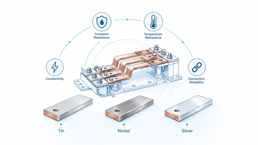
Bare copper conducts well, but exposed copper oxidizes. Copper oxide does not behave like a clean metallic contact surface. For bolted joints and terminal interfaces, oxidation can increase contact resistance over time. This is why tin plating, nickel plating, silver plating, or other surface treatments may be specified.
Tin plating is widely used because it is cost-effective, improves corrosion resistance, and helps maintain a more stable contact surface in many industrial environments. Nickel plating can be useful where higher temperature performance or diffusion barrier behavior is needed. Silver plating may be selected for demanding contact applications where very low contact resistance is required, though it is more expensive and may not be necessary for all renewable energy systems.
The plating decision should consider the mating material. If a copper busbar connects to an aluminum terminal, galvanic corrosion risk must be reviewed. The plating system, washer stack, joint compound, torque specification, and enclosure environment should be considered together. A plating callout without joint design is incomplete.
Insulation is another surface-related decision. Heat shrink, epoxy powder coating, PVC sleeves, PET film, polyimide film, or molded insulation may be used depending on voltage, operating temperature, flexibility needs, abrasion risk, and assembly process. The insulation should not cover critical contact surfaces unless the design intentionally includes exposed windows. Insulation windows need controlled dimensions because they affect creepage, clearance, and assembly repeatability.
| Surface or insulation option | Common reason for use | Key sourcing question |
|---|---|---|
| Bare copper | Lowest process cost; useful in controlled indoor conditions | Is oxidation acceptable at the joint and during storage? |
| Tin plating | General corrosion resistance and stable contact behavior | What plating thickness and contact-area requirements are needed? |
| Nickel plating | Higher temperature or barrier requirements | Will nickel’s contact behavior match the mating terminal and torque design? |
| Silver plating | Low contact resistance in demanding interfaces | Is the performance benefit worth the added cost? |
| Heat shrink | Simple insulation for straight or moderately formed parts | Can it maintain tight coverage around bends and windows? |
| Powder coating | Durable insulation for defined surfaces | How will coating thickness affect fit and creepage/clearance? |
| Film insulation | Useful for compact layered layouts | Is the film rated for the voltage, temperature, and abrasion environment? |
For EPCs, surface treatment is often connected to project life and maintenance. For OEMs, it is also connected to repeatable production. Plating thickness variation, masking quality, insulation edge control, and packaging protection can all affect line assembly and field reliability.
Creepage, clearance, insulation, and standards alignment
Renewable energy equipment often operates at elevated DC voltage. Solar strings, BESS racks, inverter DC links, and PCS cabinets may involve high voltage levels where insulation strategy is critical. Creepage and clearance are not optional details. They are fundamental safety and reliability requirements.
Clearance is the shortest air distance between conductive parts. Creepage is the shortest path along the surface of insulating material. Both depend on voltage, pollution degree, material group, environment, and applicable standard. In outdoor renewable projects, pollution, humidity, condensation, dust, and salt exposure can make creepage requirements more demanding than a clean laboratory environment.
Rigid busbars help because their geometry can be controlled. The designer can define spacing between phases or polarities, insulation windows, barriers, covers, standoffs, and support locations. But this advantage only works if the drawing includes the relevant requirements. A supplier cannot reliably protect creepage and clearance if the RFQ does not specify voltage, polarity layout, insulation material, terminal area, or assembly environment.
For low-voltage switchgear and controlgear assemblies, the IEC 61439 series is a key reference. IEC describes IEC 61439-1 as covering definitions, service conditions, construction requirements, technical characteristics, and verification requirements for low-voltage switchgear and controlgear assemblies. For grid-integrated energy storage systems, the IEC 62933 series is highly relevant. IEC 62933-5-1:2024 covers safety considerations for grid-integrated electrical energy storage systems, while IEC 62933-5-2:2025 addresses safety requirements for electrochemical-based grid-integrated systems.
Busbar suppliers do not replace the assembly manufacturer, certification body, or project engineer. However, a competent supplier can help make the busbar manufacturable and consistent with the customer’s insulation concept. This includes controlled exposed contact areas, reliable coating or sleeving, predictable bend locations, smooth edges, and proper packaging to avoid insulation damage before installation.
For OEMs exporting equipment globally, early standards discussion is valuable. A busbar that fits a prototype cabinet may still fail a compliance review if clearance, creepage, marking, insulation rating, or temperature-rise assumptions are not documented. When possible, include the target market, assembly standard, insulation requirement, and test plan in the RFQ.
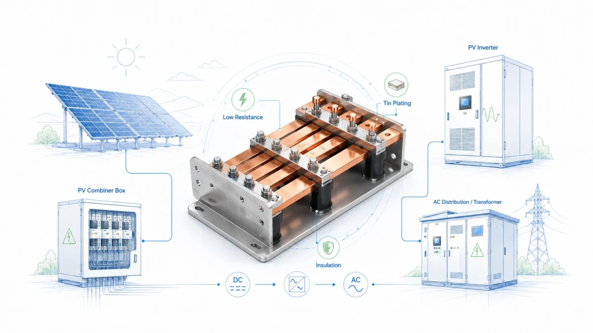
Rigid Busbars in solar PV power systems
Solar PV systems create several busbar design challenges. First, utility-scale solar farms are usually built with strong cost pressure and tight schedules. Second, PV generation creates variable current over the day, which means conductors experience thermal cycling. Third, large systems often include multiple combiner boxes, inverters, transformers, and protection devices that must be replicated across the project.
Rigid busbars are commonly used in inverter cabinets, DC combiner sections, AC distribution cabinets, and switchgear. They provide fixed routing between breakers, fuses, contactors, DC disconnects, surge protection devices, capacitors, and output terminals. Compared with hand-routed cables, they can simplify assembly and reduce layout variation.
For central inverters and large string inverter cabinets, the DC side can involve high current and compact layout. Positive and negative conductors must be separated properly, but excessive spacing increases cabinet size. A custom rigid busbar allows the designer to control spacing, layering, bend geometry, and insulation windows. In some high-density DC link layouts, laminated or closely coupled conductor arrangements may also be considered to reduce inductance, although the final design must be validated by the OEM.
For EPCs, the biggest solar-related busbar questions are usually delivery, fit, documentation, and field service. If a busbar is installed in many identical cabinets across a solar farm, even a small dimensional issue can delay a large number of units. Proper labeling, protective packaging, and part-number control are therefore important.
For OEMs, the key issues include heat rise, contact resistance, creepage/clearance, short-circuit performance, and production repeatability. A solar inverter design may have a long commercial life with multiple manufacturing batches. Once validated, the busbar should remain stable in geometry and finish across batches. This requires controlled raw material sourcing, tooling, inspection, and process documentation.
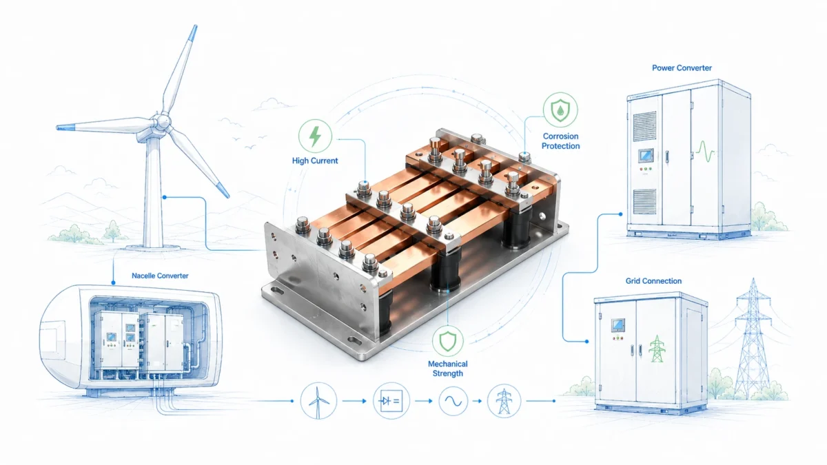
Rigid Busbars in wind energy systems
Wind energy systems combine electrical power generation with mechanical movement. This creates a more complex conductor strategy than many stationary solar systems. In wind turbines, conductors may be exposed to vibration, yaw movement, tower movement, temperature variation, and in offshore projects, corrosive marine environments.
Rigid busbars are useful in fixed sections such as converter cabinets, lower tower power distribution, switchgear, transformer interfaces, and static control cabinets. However, not every wind turbine connection should be rigid. Near moving or high-vibration interfaces, flexible laminated busbars or braided copper conductors may be better choices because they absorb movement instead of transferring stress to terminals. JUMAI’s comparison of flexible copper busbar versus solid bars is useful for understanding this trade-off.
The correct design may combine conductor types. For example, a rigid copper busbar may provide the main fixed path inside a cabinet, while a braided copper busbar provides vibration isolation between the cabinet and a transformer terminal. A flexible laminated busbar may compensate for tolerance between modules. This hybrid approach improves reliability because each conductor type is used where it performs best.
Wind applications also require attention to plating and environmental protection. Offshore wind projects may need stronger corrosion review than indoor industrial equipment. Tin plating, nickel plating, sealed enclosures, humidity control, and protective insulation should be evaluated based on the actual site environment. Packaging is also important because plated surfaces can be damaged during ocean shipping or rough handling before installation.
For OEMs, wind power busbar design should include vibration risk, support spacing, thermal cycling, cabinet accessibility, and maintenance procedures. For EPCs, the design should support fast installation and clear inspection because turbine service time is expensive. If the busbar requires difficult access or special tooling in a nacelle or tower base, maintenance cost can increase significantly.
Rigid Busbars in battery energy storage systems
Battery energy storage systems are among the most demanding applications for rigid busbars. A BESS may contain thousands of cells, many modules, multiple racks, DC collection paths, protection devices, thermal management systems, power conversion equipment, and high-energy fault scenarios. The busbar design must therefore consider current, voltage, short-circuit energy, insulation, thermal expansion, serviceability, and repeatable assembly.
Rigid busbars are used in battery racks, rack output conductors, DC bus sections, fuse and breaker interfaces, PCS cabinets, and container-level power distribution. In fixed rack sections, rigid busbars can reduce assembly variation and create a more organized power path. For module-to-module connections, flexible busbars may sometimes be preferred if cell swelling, tolerance stack-up, or service removal must be accommodated. The best design depends on the battery architecture.
BESS safety requirements are increasingly formalized. As noted above, IEC 62933-5-1 and IEC 62933-5-2 are important references for grid-integrated electrical energy storage safety. While busbars are only one component, their design affects hazards such as overheating, insulation failure, arc risk, maintenance exposure, and fault-current behavior.
Contact resistance is especially important in BESS. A slightly poor joint can become a localized heater during high charge or discharge current. If the same joint design is repeated hundreds of times, the risk becomes systemic. Therefore, the busbar design should include contact surface flatness, plating control, bolt access, torque specification, washer arrangement, and inspection method.
A BESS RFQ should identify battery chemistry, nominal and maximum voltage, continuous and peak current, expected short-circuit current, rack configuration, terminal material, service access, insulation requirements, and whether the busbar must be removed during maintenance. If the buyer only provides a rough sketch, the supplier can produce a part, but the risk of redesign is high.
| BESS design area | Why rigid busbar details matter | Useful RFQ information |
|---|---|---|
| Rack output | High current and repeated assembly | Current profile, terminal spacing, rack layout, support points |
| Module interface | Tolerance and thermal expansion | Module drawings, service procedure, expected movement or swelling |
| Fuse and breaker connection | Heat and fault-current performance | Device datasheet, torque requirement, contact area, spacing |
| PCS DC input | Compact high-power routing | DC voltage, ripple current concerns, positive/negative layout |
| Insulated busbar sections | Safety and maintenance protection | Insulation material, exposed window dimensions, voltage rating |
| Container-level distribution | Field installation and inspection | Labeling, packaging, installation sequence, documentation |
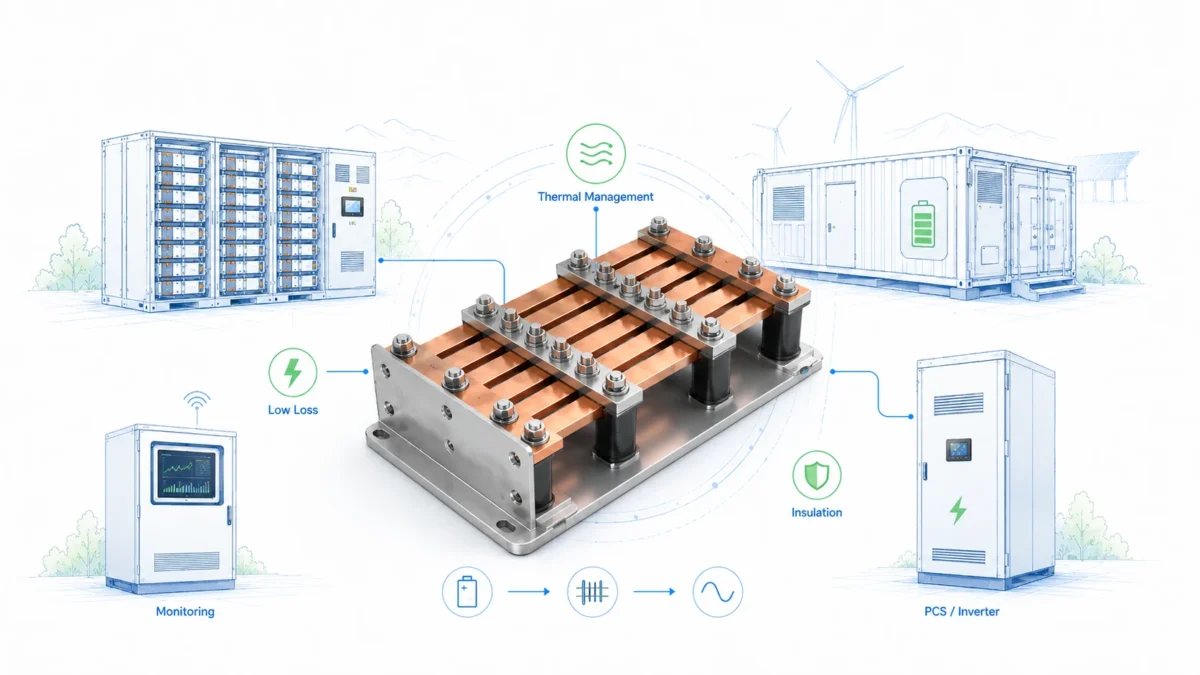
Rigid Busbars in renewable power conversion systems
Power conversion systems are the electrical heart of many renewable projects. Solar inverters convert DC from PV arrays into AC. Battery PCS units convert DC battery power into AC grid power and back again. Wind converters manage generator output and grid connection. These systems often require compact, low-loss, thermally stable, and mechanically precise conductors.
Rigid busbars in power conversion systems may connect IGBT or SiC modules, capacitor banks, DC link sections, filters, contactors, fuses, breakers, sensors, and output terminals. In these designs, geometry can influence not only resistance and heat but also inductance and electromagnetic behavior. Low-inductance busbar arrangements may require positive and negative conductors to be carefully layered or routed close together with suitable insulation. This is not a simple copper cutting task; it is a power electronics design consideration.
For OEMs using modern high-switching-frequency devices, busbar layout becomes more important. Poor layout can contribute to voltage overshoot, uneven current sharing, EMI problems, and additional thermal stress. The busbar supplier should understand which surfaces are contact areas, which sections are insulation zones, which bends are critical, and which tolerances affect module alignment.
For EPCs purchasing finished PCS or inverter cabinets, the internal busbar design is usually controlled by the OEM. However, EPCs should still evaluate whether the equipment supplier can provide documentation for thermal performance, short-circuit ratings, service clearances, and replacement parts. When a custom busbar is needed for site-specific integration, the EPC should provide exact terminal positions and field installation constraints.
JUMAI supports these projects by manufacturing custom rigid busbars according to drawings, samples, or jointly reviewed design requirements. Where needed, our broader capabilities in deep-drawn components, precision stamping, and metal accessories can support related brackets, covers, shields, terminals, and formed parts. This integrated view is useful because busbars rarely fail or succeed alone. They interact with the mechanical enclosure around them.
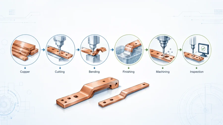
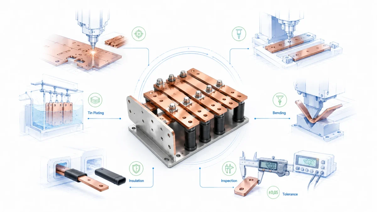
Manufacturing quality: from drawing to repeatable production
A custom rigid busbar project should move through a controlled workflow. The process normally starts with application review, then material selection, DFM review, prototype production, inspection, sample approval, production preparation, batch manufacturing, final inspection, and packaging.
The DFM stage is especially important. A drawing may be electrically correct but difficult to manufacture consistently. Problems can include bend radii that are too tight, holes too close to bends, plated areas that are difficult to mask, unrealistic flatness requirements after forming, sharp corners that create burrs, or insulation windows that are too close to bend transitions. Good DFM feedback does not weaken the design. It protects the design from production risk.
For rigid busbars, manufacturing quality usually depends on cutting or stamping accuracy, punching quality, bend consistency, burr control, surface cleaning, plating adhesion, insulation coverage, flatness, and final packaging. Burrs are not a cosmetic issue. They can damage insulation, reduce creepage distance, create handling hazards, or become local high-field points. Deburring and edge finishing should be defined for critical parts.
Plating and insulation should be controlled as processes, not treated as afterthoughts. Plating thickness should match the application and drawing requirement. Insulation should maintain coverage through handling and installation. Contact areas should remain clean and protected. If masking is required, the drawing should clearly show exposed copper or plated contact windows.
| Production stage | Key control point | Why it matters |
|---|---|---|
| Material preparation | Grade, thickness, temper, certificate | Prevents hidden conductivity or forming differences |
| Cutting or stamping | Profile tolerance, edge quality, burr height | Supports fit, safety, and insulation reliability |
| Punching | Hole diameter, position, slot quality | Controls terminal alignment and assembly repeatability |
| Bending | Angle, radius, bend sequence, springback | Determines whether the part fits the cabinet without force |
| Deburring and cleaning | Edge smoothness and surface cleanliness | Reduces insulation damage and plating problems |
| Plating | Thickness, adhesion, contact area quality | Protects against oxidation and supports stable joints |
| Insulation | Coverage, window position, dielectric rating | Supports safety and creepage/clearance requirements |
| Inspection | Dimensions, finish, documentation | Helps the buyer approve and trace production batches |
| Packaging | Surface protection, part separation, labels | Prevents damage before installation |
For OEM programs, the transition from prototype to volume production must be planned. A prototype can sometimes be made manually, but production requires repeatable tooling and inspection. If the supplier does not explain how the prototype process will become a production process, the buyer should be cautious.
Cost drivers that buyers should understand
Rigid busbar pricing is not only a function of copper weight. Copper mass matters, especially when copper prices move, but the final cost also depends on processing complexity, tooling, tolerance, plating, insulation, inspection, packaging, and order quantity.
A simple flat copper bar with two holes and tin plating is very different from a multi-bend insulated busbar with tight flatness, masked contact windows, special plating, serialized marking, and full inspection documentation. The second part may use similar copper mass but require much more engineering and process control.
Buyers sometimes try to reduce cost by forcing the smallest possible copper section. This may reduce material cost but increase heat, voltage drop, and validation risk. Other buyers oversize copper because they are uncertain about current and temperature rise. That reduces electrical risk but can increase cost, weight, and assembly difficulty. The better approach is to share the real application requirements and allow the supplier to help optimize.
| Cost driver | How it affects price | How to control it intelligently |
|---|---|---|
| Copper mass | More material increases cost and shipping weight | Optimize cross-section using current, duty cycle, and thermal data |
| Geometry complexity | More bends and tight tolerances require more setup and inspection | Simplify routes where possible and allow practical bend radii |
| Tooling | Stamping tools or fixtures may be needed for repeatability | Match tooling investment to expected volume and product life |
| Plating | Tin, nickel, or silver add process cost | Choose plating based on environment and joint requirements, not habit |
| Insulation | Coating, sleeving, or film insulation adds labor and validation needs | Define voltage, temperature, window dimensions, and coverage clearly |
| Documentation | Certificates and detailed reports require quality resources | Request only the documentation needed for project approval |
| Packaging | Export packaging and surface protection add cost | Specify handling risk and required protection level early |
| Quantity | Low-volume prototypes have higher unit cost | Separate prototype pricing from production pricing |
For EPCs, the most important commercial point is total installed cost, not piece price. A cheaper busbar that requires field modification is expensive. For OEMs, the most important point is total product cost over the production life. A slightly higher unit price may be justified if it reduces assembly time, rework, warranty risk, or inventory complexity.
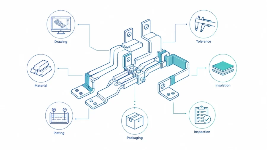
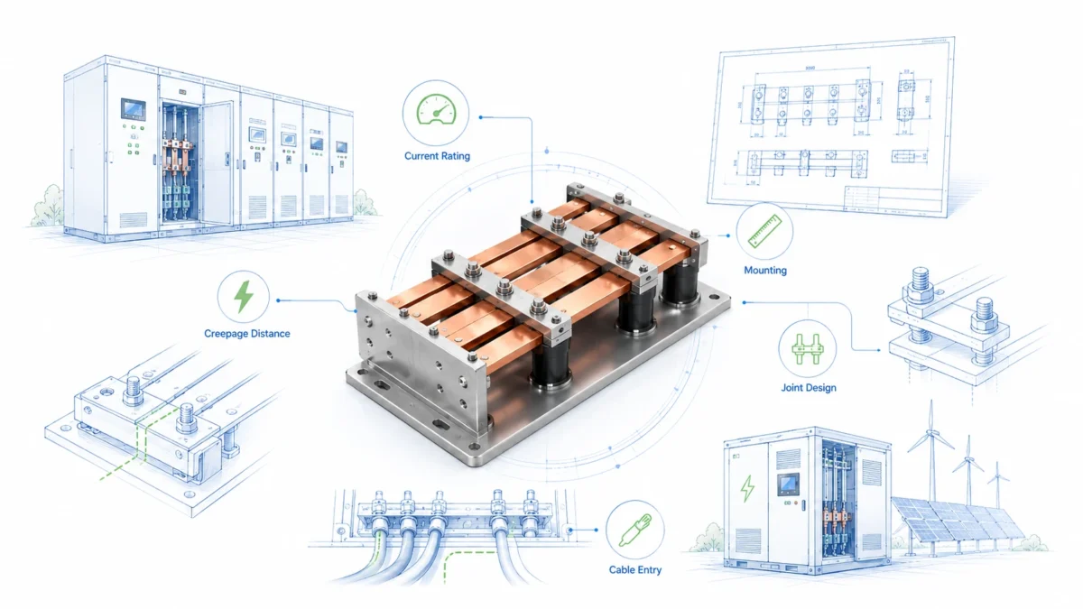
What to include in a professional rigid busbar RFQ
A strong RFQ helps the supplier quote faster and more accurately. It also helps the buyer receive comparable quotations from different suppliers. For renewable energy projects, the RFQ should include both the part drawing and the system context.
At minimum, provide a 2D drawing with dimensions, tolerances, material grade, thickness, finish, and quantity. If the part has bends or complex routing, provide a 3D file such as STEP if available. Mark contact surfaces, insulation windows, bend directions, critical dimensions, and inspection points. Provide the expected annual volume and prototype quantity separately.
The electrical information should include nominal voltage, maximum voltage, continuous current, peak current, duty cycle, acceptable temperature rise if known, and expected fault-current condition if relevant. The environment information should include indoor or outdoor use, enclosure type, ambient temperature range, humidity, salt mist or corrosion exposure, vibration level, and whether the busbar will be serviced in the field.
The mechanical information should include terminal material, bolt size, torque requirement, support points, available installation space, assembly sequence, and any special tool access constraints. If the busbar connects to purchased devices such as breakers, contactors, capacitors, fuses, or power modules, include the device datasheets or terminal drawings.
| RFQ item | Good information to provide | Why it helps |
|---|---|---|
| Drawing | 2D PDF with dimensions, tolerances, material, finish | Allows clear quoting and inspection planning |
| 3D file | STEP model for bent or spatial parts | Reduces bend direction and interference errors |
| Electrical data | Voltage, current, duty cycle, temperature rise target | Supports cross-section and thermal review |
| Fault data | Short-circuit current and clearing time if known | Supports mechanical and support discussion |
| Environment | Temperature, humidity, salt, dust, enclosure type | Supports plating and insulation choice |
| Assembly data | Bolt size, torque, terminal material, tool access | Supports contact design and manufacturability |
| Compliance | IEC, UL, customer standards, test plan | Helps align documentation and design assumptions |
| Quantity | Prototype, pilot, annual production | Supports tooling and process recommendation |
| Packaging | Export method, surface protection, labeling | Prevents damage and installation confusion |
A vague RFQ forces suppliers to assume. Different suppliers may make different assumptions, making quotations difficult to compare. A detailed RFQ creates more accurate pricing, fewer design revisions, and a smoother prototype approval process.
How to compare rigid busbar suppliers
Many rigid busbar quotations look similar at first. They may list copper grade, thickness, plating, quantity, unit price, and lead time. The real difference is often hidden in engineering support, process control, documentation, and production consistency.
A strong supplier asks questions before quoting when the application is complex. This is not a delay tactic. It is a sign that the supplier understands the risk. If a supplier quotes a high-current renewable energy busbar from only width, thickness, and quantity, the buyer should be careful. That supplier may be treating the part as a simple copper strip instead of a system-critical component.
Evaluate whether the supplier can explain the manufacturing route. Can they describe how the part will be cut, punched, bent, deburred, plated, insulated, inspected, and packaged? Can they support sample approval? Can they control plating and insulation windows? Can they review DFM? Can they protect parts during export shipment? Can they provide material certificates and inspection reports if required?
| Evaluation area | Strong supplier behavior | Red flag |
|---|---|---|
| Engineering review | Asks about current, temperature, voltage, environment, and assembly | Quotes instantly from copper size only |
| Material transparency | States grade, temper, equivalent options, and certificate plan | Uses vague terms such as “red copper” without details |
| Manufacturing route | Explains cutting, punching, bending, deburring, plating, insulation, and inspection | Cannot explain how prototypes become repeatable production |
| DFM support | Suggests practical changes to reduce risk or cost | Treats drawing problems as the buyer’s issue only |
| Documentation | Can provide inspection reports, material certificates, and plating records when needed | Avoids documentation questions |
| Packaging | Protects contact surfaces and insulation during shipping | Ships parts loosely with surface damage risk |
| Commercial flexibility | Separates prototype, pilot, and production pricing | Uses one rigid price model for all stages |
JUMAI’s advantage is the combination of copper busbar manufacturing and precision metal forming experience. Because we also work with stamped and deep-drawn components, our team understands that busbars must fit into real equipment with brackets, covers, supports, terminals, and enclosure constraints. This broader manufacturing perspective helps EPCs and OEMs reduce design risk before production.
How JUMAI supports EPCs and OEMs
JUMAI manufactures custom rigid, flexible, and braided copper busbars for high-current applications. For renewable energy systems, our role is to help customers turn electrical and mechanical requirements into manufacturable parts that support safe, efficient, and repeatable assembly.
For rigid busbars, we focus on conductor geometry, copper grade, thickness, bend accuracy, hole alignment, burr control, contact surface quality, plating, insulation, flatness, and packaging. For flexible copper busbars, we focus on laminated foil structure, terminal bonding, bend zones, insulation, and tolerance compensation. For braided copper busbars, we focus on strand structure, terminal compression, flexibility, and vibration absorption. This matters because a renewable energy system may need all three conductor types in different locations.
We can support projects from early design review to sample production and batch manufacturing. A typical cooperation process includes reviewing drawings or samples, discussing application conditions, suggesting manufacturability improvements, confirming material and surface treatment, producing samples, supporting inspection, and preparing production after approval. For OEM customers, we can also discuss tooling strategy, batch consistency, labeling, and packaging. For EPC customers, we can focus on project quantity, installation sequence, documentation, and delivery schedule.
JUMAI’s website presents our capabilities in custom copper busbars, high-ampacity precision copper busbar manufacturing, and deep-drawn components. These capabilities are useful for renewable energy projects because the conductor is often part of a larger mechanical and electrical assembly.
The best time to involve JUMAI is before the design is frozen. Early review can identify bend risks, plating issues, insulation window problems, assembly access concerns, and cost-saving opportunities. If the design is already fixed, we can still manufacture according to the drawing, but early collaboration usually creates a better balance between cost, reliability, and production speed.
Practical design checklist before ordering
Before sending an RFQ for rigid busbars, EPCs and OEMs should review the checklist below. It is not a replacement for engineering validation, but it helps avoid the most common sourcing gaps.
| Checklist question | Why it matters |
|---|---|
| What is the nominal and maximum system voltage? | Determines insulation, creepage, clearance, and marking requirements |
| What is the continuous and peak current? | Supports cross-section, temperature rise, and joint design |
| What is the duty cycle? | A short peak current and continuous current create different thermal needs |
| What ambient temperature and enclosure condition apply? | A sealed hot cabinet differs from open-air installation |
| What fault-current condition should be considered? | Affects busbar support, spacing, bracing, and assembly safety |
| What material grade and temper are required? | Affects conductivity, bending, stiffness, and documentation |
| What plating or surface treatment is needed? | Affects corrosion resistance and contact stability |
| What insulation system is required? | Affects safety, dimensions, and installation protection |
| Which surfaces must remain exposed for contact? | Prevents coating or insulation errors |
| What bolt size and torque are used? | Affects hole design, washer stack, and contact pressure |
| Are there tight spaces or tool access limitations? | Prevents assembly problems after parts arrive |
| Are 3D files available? | Reduces bend direction and interference mistakes |
| What standards or customer specifications apply? | Aligns testing, documentation, and design assumptions |
| How many prototypes and production parts are required? | Helps choose the correct manufacturing and tooling route |
| How should the parts be packaged and labeled? | Prevents contact damage and installation confusion |
This checklist is especially important for renewable energy systems because the same conductor design may be repeated across many cabinets, racks, or projects. A small error in the first design can become a large cost in the field.
The business case for custom Rigid Busbars
The business case for custom rigid busbars is not only about electrical efficiency. It is about reducing risk across the project lifecycle. A well-designed rigid busbar can reduce installation time, improve assembly repeatability, support thermal management, reduce voltage drop, simplify inspection, and create a cleaner internal layout.
For EPCs, these benefits can translate into fewer field modifications, faster commissioning, clearer documentation, and lower maintenance risk. In renewable projects, schedule delays can be expensive because grid connection, owner acceptance, and revenue start dates are tightly linked. A busbar that arrives correctly labeled, protected, and ready to install can save more than its unit price suggests.
For OEMs, the benefits appear in production consistency and product reliability. A custom rigid busbar can reduce operator variation, support fixture-based assembly, and make inspection easier. Once validated, the same busbar can be reproduced across production batches. This helps the OEM control quality and scale output as renewable energy demand grows.
The strongest commercial value appears when the busbar supplier is involved early enough to optimize the design. Copper is valuable, so unnecessary mass should be removed where possible. But reliability is also valuable, so undersizing or simplifying beyond safe limits is a false economy. The goal is not the cheapest copper part. The goal is the most reliable, manufacturable, and cost-effective conductor for the system.
Renewable energy systems will continue to become larger and more power-dense. Solar PV, wind power, battery storage, hybrid plants, and renewable-powered industrial infrastructure all need efficient current paths. EPCs and OEMs that treat rigid busbars as engineered components, rather than commodity strips, will be better positioned to control performance, cost, and schedule.
Conclusion: design the conductor as part of the system
Rigid Busbars are a small part of the visual footprint of a renewable energy project, but they carry a large share of the electrical responsibility. They connect power sources, conversion equipment, storage systems, protection devices, and grid interfaces. When designed well, they improve efficiency, safety, assembly repeatability, and long-term reliability. When designed poorly, they can create heat, voltage drop, installation difficulty, and field risk.
For EPCs, the key is to specify enough system context so the busbar supports fast installation and project approval. For OEMs, the key is to design for repeatable production, validation, and serviceability. For both groups, early supplier involvement can prevent avoidable redesign.
JUMAI supports renewable energy customers with custom rigid copper busbars, flexible copper busbars, braided copper busbars, precision stamped parts, deep-drawn components, and related metal accessories. Whether the project involves solar inverters, wind power systems, BESS racks, PCS cabinets, DC distribution, switchgear, or compact renewable power modules, our team can review your drawings and help develop a manufacturable conductor solution.
To start a project, prepare the drawing, current and voltage requirements, environmental conditions, surface treatment preference, insulation requirements, quantity, and target schedule. Then contact JUMAI through our copper busbar solutions page or contact page to discuss a custom rigid busbar solution for your renewable energy system.